


Provide 4 pins DIP switch for function
settings, where "ON" is enable valid
terminal.
The device needs to be powered on
again to change the status of DIP switch.
DIP switches definition as follows:
DIP
Definition Operation
1
Restore
factory
defaults
Set the DIP switch to ON, the
device will root automatically and
restore to factory settings, then turn
off the DIP switch.
2
Reserved
-
3
Reserved
-
4
Reserved
-
【
I/O Port Connection
】
Model 1, Model 2, Model 3, Model 4,
Model 9, Model 10, Model 11,
Model 12, Model 17, Model 18,
Model 21, Model 22, Model 23,
Model 24, Model 25, Model 31 and Model 32 of this device
provide 8-pin 3.81mm pitch terminal blocks and I/O port with 2
inputs and 2 outputs. This device can detect and send I/O
input status to management software, operators can set the
conditions of alarm status via management software. When
the I/O input status meets the set alarm conditions, the I/O
output alarm would be triggered. The pin definitions of I/O port
are shown as follows:
I/O port
PIN
Definition
DI data signal input 1
DI1+, DI1-
I/O signal input
DI data signal input 2
DI2+, DI2-
DO data signal output 1 DO1+, DO1-
I/O relay output
DO data signal output 2 DO2+, DO2-
【
Console Port Connection
】
The device provides 1 channel procedure debugging port
based on RS232 serial port, and can conduct device CLI
command line management after connected to PC. The
interface adopts RJ45 port, the RJ45 pin definition as follows:
Pin No.
2
3
5
Definition
TXD
RXD
GND
【
Checking LED Indicator
】
The device provides LED indicators to monitor the device
working
status
with
a
comprehensive
simplified
troubleshooting; the function of each LED is described in the
table as below:
LED
Indicate Description
P1/P2/PWR
ON
PWR is connected and running
normally
OFF
PWR is disconnected and
running abnormally
ALM
ON
Power supply, port link alarm
OFF
Power supply, port link without
alarm
RUN
ON
The device is powered on or the
device is abnormal.
OFF
The device is powered off or the
device is abnormal.
Blinking
Blinking 1 time per second,
system is running well.
Link/Act
(1-4/8)
ON
The Ethernet interface has
established an active network
connection.
Blinking
The Ethernet interface is in a
network activity state.
OFF
Ethernet
port
has
not
established
valid
network
connection
PoE(1-4/8)
ON
POE port is powering other
devices normally
OFF
POE is disabled or disconnected
DO(1-2)
ON
I/O has output alarm information
OFF
I/O has no output alarm
information
DI(1-2)
ON
I/O has input information
OFF
I/O has no input information
【
Logging in to WEB Interface
】
This device supports WEB management and configuration.
Computer can access the device via Ethernet interface. The
way of logging in to device’s configuration interface via IE
browser is shown as below:
Step 1
Configure the IP addresses of computer and the
device to the same network segment, and the
network between them can be mutually accessed
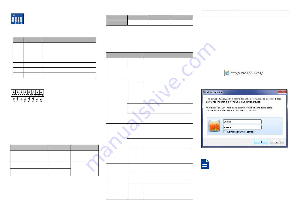
Step 2
Enter device’s IP address in the address bar of the
computer browser.
Step 3
Enter device’s user name and password in the
login window as shown below.
Step 4
Click “OK” button to login to the WEB interface of
the device.
Notes:
The default IP address of the device is “192.168.1.254”.
The default user name and password of the device is
“admin”.
If the username or password is lost, user can restore it to
factory settings via device DIP switch or management
software; all modified configurations will be cleared


