

- 2 -
7.
Ethernet port Link/ACT LEDs(1~28)
8.
1000Base-FX SFP port
9.
Rackmount ears
10.
Relay 1 output terminal block
11.
Power 1 input power socket
12.
Grounding screw
13.
Relay 2 output terminal block
14.
Power 2 input power socket
15.
10/100/1000BaseT(X) or 1000Base SFP slot combo ports
【
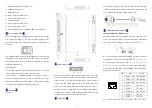
Power supply input
】
The switch support dual redundant power supplies: Power Supply
1 (P1)
and Power Supply 2 (P2). The switch rear panel provides
power sockets for AC100~240V power entered.
Socket diagram is
as follows:
The redundant power can be used independently. P1 and P2 can
supply power at the same time, once either of these two powers
fails, another power can acts as backup automatically to ensure
reliability of the network.
Important notice:
1. Power ON operation: Please connect to the device at first and
then connect to the power supply with power cable.
2. Power switch “—” means power ON, “O” means power OFF.
3. Power OFF operation: First, the powers switch to the "O" side
and then disconnect the power supply. Finally disconnect the
connection between the device and the power cord.
【
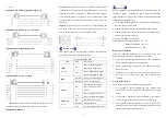
Dimension
】
Unit (mm)
【
Relay connection
】
Relay access terminals in the rear panel of the device, next to the
power input parts, R+ and R- are in the middle of the relay alarm
output section. It is used to detect both power failure and port
failure. The open circuit state in normal non alarm state, when
there is any alarm information to the closed state. This series of
switch device have 2 relay alarm output, external alarm lights or
alarm buzzer or external switch signal acquisition device in order
to timely notify operators when an alarm occurs.
【
Console port
】
This switch provided 1pcs procedure test port based in serial port.
It adopts RJ45 interface, located in top panel, can configure the
CLI command through RJ45 to DB9 female cable.
【
Communication connector
】
10/100/1000BaseT(X) Ethernet port
The pinout define of RJ45 port display as below, connect by UTP
or STP. The connect distance is no more than 100m. 100Mbps is
used 120
Ω
of UTP 5, 10Mbps is used 120
Ω
of UTP 3 ,4, 5.
RJ 45 port support automatic MDI/MDI-X operation. That can
connect the PC, Server, Converter and HUB. Pin 1, 2, 3, 4, 5, 6, 7,
8
Corresponding connections in MDI. 1→3, 2→6, 3→1,
4
→
7,
5
→
8, 6
→
2, 7
→
4, 8
→
5, are used as cross wiring in the MDI-X
port of Converter and HUB. In MDI/MDI-X, 100/1000Base-TX
PIN defines is as follows:
PIN
MDI
MDI-X
1
BI_DA+/TX+ BI_DB+/RX+
2
BI_DA-/TX-
BI_DB-/RX-
3
BI_DB+/RX+ BI_DA+/TX+
4
BI_DC+/
—
BI_DD+/
—
5
BI_DC-/
—
BI_DD-/
—
6
BI_DB-/RX-
BI_DA-/TX-
7
BI_DD+/
—
BI_DC+/
—
8
BI_DD-/
—
BI_DC-/
—
Note
:
10Base-T/100Base-TX, “TX
±
”transmit data
±
, “RX
±
”receive data
±
,
1
8


