


- 2 -
below:
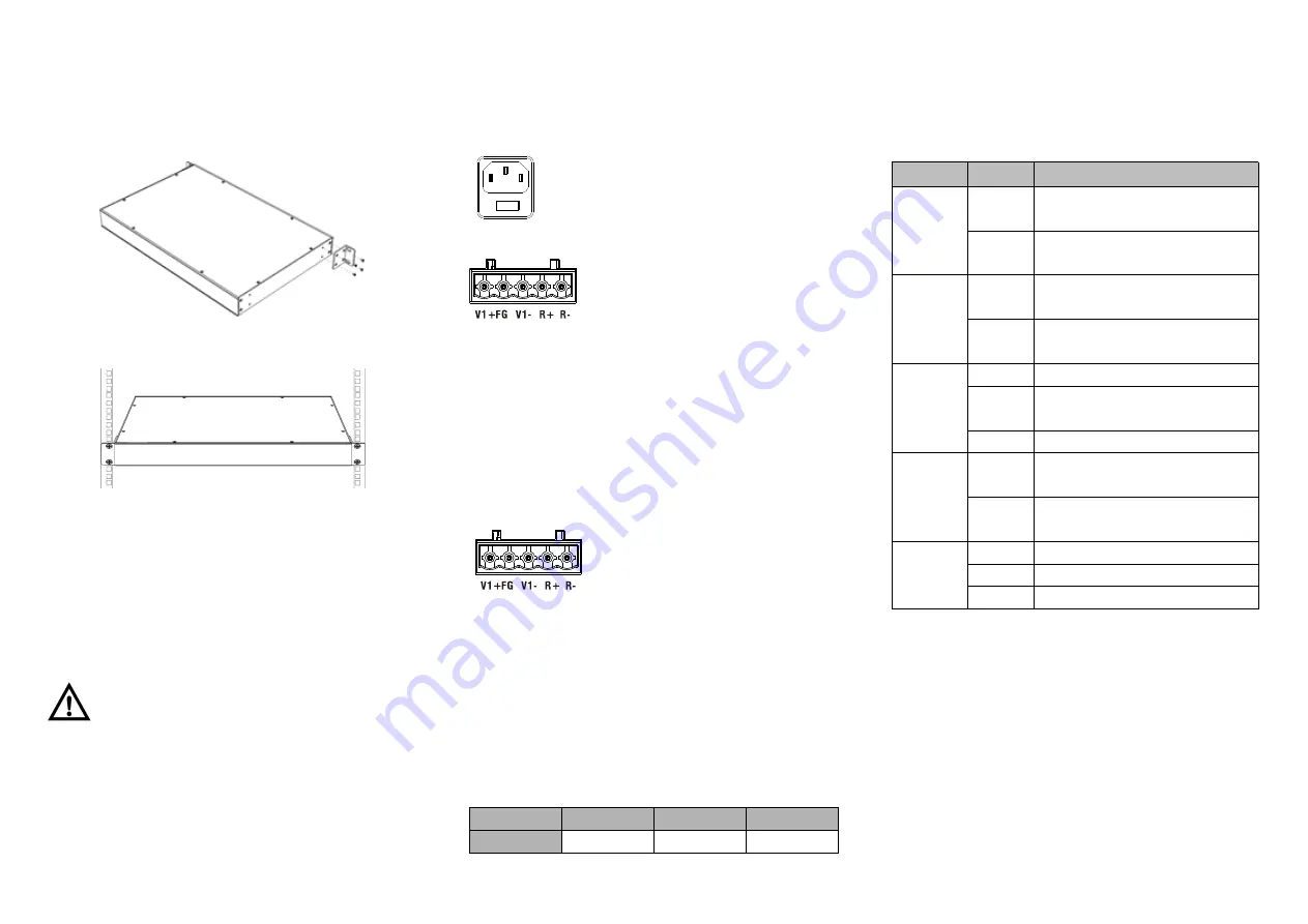
Step 1 Select the device mounting position and ensure
enough mounting size is reserved.
Step 2 Adopt 4 bolts to install the mounting lugs in the
device position as figure below.
Step 3 Place the device in the rack; adopt 4 bolts to fix two
sides mounting lugs in the rack.
Step 4 Check and confirm the product is firmly installed on
the rack, then mounting ends.
【
Disassembling Device
】
Step 1 Power off device.
Step 2 Adopt screw driver to loosen the 4 bolts fixed on
the mounting lugs in the rack.
Step 3 Remove the device away from the rack,
disassembling ends.
Note before powering on:
Power ON operation: First insert the power supply terminal
block into the device power supply interface, and then plug
the power supply socket and power on.
Power switch “—” means power ON, “O” means power OFF.
Power OFF operation: First, put the powers switch to the "O"
side and then disconnect the power supply. Finally disconnect
the connector between the device and the power cord. Please
notice the operation order above.
【
Power Supply Connection
】
AC power supply
This device provides 2 AC power supply
access interfaces which come with a switch.
The
power
supply
input
range
is
100~240VAC/DC.
DC power supply
This device provides 2 DC power
supplies which are 5-pin 5.08mm pitch
terminal blocks.The power supply
occupies 3 pins and supports anti-reverse connection.
Power supply range: 36~72VDC
【
Restoring Default Settings
】
RESET is restoring default settings button. Restoring default
settings steps as follows: Press and hold the RESET button,
disconnect the power supply and then power on the device,
wait for about 3~4 seconds to restore the factory settings.
【
Relay Connection
】
R+ and R- are the relay alarm output
section. They are open circuit in normal
non alarm state, closed when any
alarm information occurs. The product
supports 2-way relay alarm output, externally connected to
alarm lights or alarm buzzer or other switching value
collecting device in order to timely notify operators when the
alarm occurs.
【
Console Port Connection
】
The series products provide 1 program debugging port
based on RS-232 serial port which can conduct device CLI
command management after connecting to PC. It adopts
RJ45 interface, its pin definition is showed as follows:
Pin No.
2
3
5
Definition
TXD
RXD
GND
【
Checking LED Indicator
】
The series products provide LED indicators to monitor the
device working status with a comprehensive simplified
troubleshooting; the function of each LED is described in the
table as below:
LED
State
Description
P1
ON
Power supply is connected or
running normally
OFF
Power supply is disconnected or
running abnormally
P2
ON
Power supply is connected or
running normally
OFF
Power supply is disconnected or
running abnormally
RUN
Blinking System is running normally
OFF
System is not running or running
abnormally
ON
System is running abnormally
ALM
ON
Power supply or the port’s link is
alarming.
OFF
Power and the port’s link exist no
alarm
Link
(G1-G28)
ON
Port connection is active
Blinking Data transmitted
OFF
Port connection is not active
【
Logging in to WEB Interface
】
This device supports WEB management and configuration.
Computer can access the device via Ethernet interface. The
way of logging in to device’s configuration interface via IE
browser is shown as below:
Step 1
Configure the IP addresses of computer and the
device to the same network segment, and the
network between them can be mutually
accessed.
Step 2
Enter device’s IP address in the address bar of


