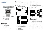


Check if the DIN-Rail mounting kit is installed firmly.
Step 1
Insert the bottom of DIN-Rail mounting kit (one side
Step 2
with spring support) into DIN-Rail, then insert the
top into DIN-Rail.
Tips:
Insert a little to the bottom, lift upward and then insert
to the top.
Check and confirm the product is firmly installed on
Step 3
DIN-Rail, then mounting ends.
【
Disassembling DIN-Rail
】
Power off device.
Step 1
After lifting the device upward slightly, first shift out
Step 2
the top of DIN-Rail mounting kit, and then shift out
the bottom of DIN-Rail, disassembling ends.
Notice before power on:
Power ON operation: First insert the power supply
terminal block into the device power supply interface,
then plug the power supply plug contact and power on.
Power OFF operation: First, remove the power plug,
then remove the wiring section of terminal block. Please
pay attention to the above operation sequence.
【
Power Supply Connection
】
The device provides 6-pin 5.08mm pitch power supply
terminal blocks and power supply occupies the left 4 pins. It
supports two independent DC power
supply systems, P1 and P2. Power supply
provides built-in 3A overcurrent protection,
and supports non-polarity and redundant
backup. Power supply range: 12
~
48VDC.
【
Relay Connection
】
This device provides 6-pin 5.08mm pitch
input terminal blocks, and the relay
occupies the right 2 pins. Relay terminals
are a set of normally open contacts of the
device alarm relay. They are open circuit in
the state of normal non alarm, closed when any alarm
information occurs. For example, they are closed when
powered off, and send out alarm. The switch supports 1 relay
alarm information output that supports DC power supply alarm
and port alarm information output. It can be connected to
alarm light, alarm buzzer or other switching value collecting
devices; it can timely inform operators when the alarm occurs.
【
DIP Switch Settings
】
The device provides 4-pin DIP switch for function
setting, in which “ON” is the enabled end. The
definitions of DIP switch are as follows:
DIP Definition
Operation
1
Storm suppression
Set the DIP to “ON”
2
Jumbo frame
(
9600 Bytes
)
Set the DIP to “ON”
3
Relay alarm
Set the DIP to “ON”
4
IEEE802.3az Energy
Efficient
Set the DIP to “ON”
【
Checking LED Indicator
】
The device provides LED indicators to monitor its operating
status, which has simplified the overall troubleshooting
process. The function of each LED is described in the table
below:
LED
Indicate Description
P1/P2
ON
Power supply is running normally
OFF
Power supply is disconnected or
LED
Indicate Description
running abnormally
ALM
ON
Power supply or port connection has
alarm
OFF
Power supply and port has no alarm
or the alarm function is disabled.
RUN
ON
Device is not started or abnormal
OFF
The device is powered off or the
device is abnormal.
Blinking
Blinking 1 time per second, the
device is running normally.
G1-G12
ON
Ethernet port has established a valid
network connection.
Blinking
Ethernet port is in an active network
status.
OFF
Ethernet port has not established
valid network connection
【
Specification
】
Panel
Gigabit copper port
10/100/1000Base-T(X)
self-adaption, RJ45,
Automatic Flow Control,
Full/Half Duplex Mode,
MDI/MDI-X Autotunning
Gigabit SFP slot
100/1000Base-X
self-adaption, SFP slot
2.5G SFP slot
100/1000/2.5GBase-X
self-adaption, SFP slot
Console port
Reserved
Alarm interface
6-pin 5.08mm pitch terminal
blocks, including 2-pin alarm
terminal blocks. It supports 1
channel relay alarm
information output, current
load capacity is 1A@30VDC
or 0.3A@125VAC
Indicator
Running Indicator, Alarm


