

normal non alarm state, closed when any alarm information
occurs. The relay can externally connect to alarm lights or
alarm buzzer or other switching value collecting device in
order to timely notify operators when the alarm occurs.
【
Console Port Connection
】
The series products provide 1 program debugging port
based on RS-232 serial port which can conduct device CLI
command management after connecting to PC. The
interface adopts RJ45 port, the RJ45 pin definition as
follows:
Pin No.
2
3
5
Definition
TXD
RXD
GND
【
Checking LED Indicator
】
The series products provide LED indicators to monitor the
device working status with a comprehensive simplified
troubleshooting; the function of each LED is described in the
table as below:
LED
Indicate
Description
P1
ON
PWR is connected and running
normally
OFF
PWR is disconnected and running
abnormally
P2
ON
PWR is connected and running
normally
OFF
PWR is disconnected and running
abnormally
RUN
Blinking
The system is running normally
OFF
The system is not running or
running abnormally
ON
System is running abnormally
ALM
ON
Power supply or the port link is
alarming.
OFF
Power and the port link have no
alarm
Link
(G1-G2
ON
Port has established valid
network connection
LED
Indicate
Description
4/G28,
X1-X4)
Blinking
Port is in a network
communication status
OFF
Port hasn’t established valid
network connection.
【
Logging in to WEB Interface
】
This device supports WEB management and configuration.
Computer can access the device via Ethernet interface. The
way of logging in to device’s configuration interface via IE
browser is shown as below:
Step 1
Configure the IP addresses of computer and the
device to the same network segment, and the
network between them can be mutually accessed
Step 2
Enter device’s IP address in the address bar of
the computer browser.
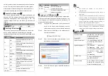
Step 3
Enter device’s username and password in the
login window as shown below.
Step 4
Click “OK” button to login to the WEB interface of
the device.
Note:
The default IP address of the device is
“192.168.1.254”.
The default username and password of the device is
“admin123”.
If the user name or password is lost, user can restore it
to factory settings via restoring factory setting button
or management software; all modified configurations
will be cleared after restoring to factory settings, so
please backup configuration file in advance.
Please refer to user manual for specific configuration
method of logging in to WEB interface and other
configurations about network management function.
【
Specification
】
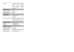
Panel
10GbE interface
10GbE SFP+ port (10Gigabit /
Gigabit self-adaption)
Gigabit SFP
1000Base-SFP slot
1000M Combo port
10/100/1000Base-T(X) RJ45
or 1000 Base-SFP interface
optional
Gigabit copper port
10/100/1000 Base-T(X)
self-adapting RJ45 port,
half/full duplex self-adapting or
compulsive working mode,
support MDI/MDI-X
self-adapting
Console port
CLI command management
port (RS-232), RJ45
Alarm interface
5-pin 5.08mm pitch terminal
block (R+/R-), support 2 relay
alarm information outputs