


Model V-Model VIII provides 2 AC
power sockets with switch, PWR1 and
PWR2, and supports AC power supply
input. The power input supports 1 single
power supply input or 2 power supply
inputs at the same time; When two power supply input at the
same time, it supports redundant backup of power supply. If
one power supply fails, the device can still work normally
without interruption. Power supply input range:
110VAC/220VAC (85~264VAC).
【
Relay Connection
】
Provide 3-pin 5.08mm pitch terminal block,
support 1 relay alarm output. In power off
situation, R- and R+ are a group of normally
closed contacts. After powered on, the relay is
open circuit in normal non-alarm state by default, closed when
any alarm information occurs. The relay supports power
supply alarm or network abnormality alarm. It can be
connected to alarm light or alarm buzzer or other switching
value collecting devices, which can timely inform operators
when the alarm occurs.
【
Console Port Connection
】
Provide 1 program debugging port based on
RS-232 serial port which can conduct device CLI
command management after connecting to PC.
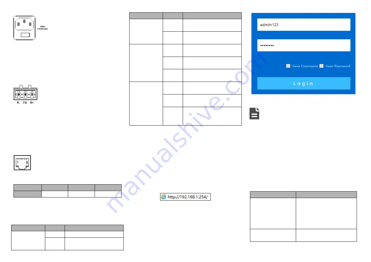
The interface adopts RJ45 port, the RJ45 pin definitions are
as follows:
Pin No.
2
3
5
Definition
TXD
RXD
GND
【
Checking LED Indicator
】
Provide LED indicators to monitor its operating status, which
has simplified the overall troubleshooting process. The
function of each LED is described in the table below:
LED
Indicate Description
P1/P2
ON
Power P1/2 is running normally
OFF
Power P1/2 is disconnected or
running abnormally
LED
Indicate Description
ALM
ON
Power supply or port link has
alarm
OFF
Power supply, port link without
alarm
RUN
ON
The device is running
abnormally
Blinking
Blinking 1 time per second,
system is running normally
OFF
The device is powered off or
the device is abnormal.
LINK
(G1-24/28/32/40
, X1-X4)
ON
Ethernet port has established a
valid network connection
Blinking
Ethernet port is in an active
network status
OFF
Ethernet port has not
established valid network
connection
【
Logging in to WEB Interface
】
Support WEB management and configuration. Computer can
access the device via Ethernet interface. The way of logging
in to device’s configuration interface via browser is shown as
below:
Configure the IP addresses of computer and the
Step 1
device to the same network segment, and the
network between them can be mutually accessed.
Enter device’s IP address in the address bar of the
Step 2
computer browser.
Enter device’s username in the login window as
Step 3
shown below.
Click “Login” button to login to the WEB interface of
Step 4
the device.
Note:
The default IP address of the device is “192.168.1.254”.
The default username and password of the device are
“admin123”.
If the username or password is lost, user can restore it to
factory settings via management software; all modified
configurations will be cleared after restoring to factory
settings, so please backup configuration file in advance.
Please refer to user manual for specific configuration
method of logging in to WEB interface and other
configurations about network management function.
【
Specification
】
Panel
Gigabit copper port
10/100/1000Base-T(X)
self-adaption or forced mode,
RJ45, Automatic Flow Control,
Full/Half Duplex Mode,
MDI/MDI-X Autotunning
Gigabit SFP
100/1000Base-X self-adaption
or forced mode, SFP slot


