


Step 4
Check and confirm the product is mounted firmly
on the rack, mounting ends.
【
Disassembling Device
】
Step 1
Power off the device.
Step 2
Adopt screw driver to loosen the 4 bolts fixed on
the mounting lugs in the rack.
Step 3
Shift out the device from rack, disassembling
ends.
Notice before power on:
Power ON operation: First insert the power supply
terminal block into the device power supply interface,
then plug the power supply plug contact and power
on.
Power OFF operation: First, remove the power plug,
then remove the wiring section of terminal block.
Please pay attention to the above operation sequence.
Please be aware of the power input range supported
by the device before powering on. Use the
recommended voltage of the device to avoid device
damage.
【
Console Port Connection
】
Provide 1 program debugging port based on
RS-232 serial port which can conduct device
CLI command management after connecting to
PC. The interface adopts RJ45 port, the RJ45 pin definitions
are as follows:
Pin No.
2
3
5
Pin
TXD
RXD
GND
Definition
【
Checking LED Indicator
】
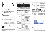
As shown above, the device provides LED indicators to
monitor the device working status with a comprehensive
simplified troubleshooting; the function of each LED is
described in the table as below:
Indicator Panel ID Status
Definition
Power
indicator
PWR
Indicator off
The switch is not
powered on.
The Green
light keeps on
The switch is powered
on.
System
indicator
SYS
Indicator off
The system is not
started.
Flashing
green
The system is starting
or the system has
started successfully
Ethernet
port
indicator
(1-24)
Link/Act
/Speed
Indicator off Port is not Link
The orange
light keeps on
Port 10/100M link up
Flashing
orange
Port 10/100M data
transmission
The Green
light keeps on
Port 1000M Link Up
Flashing
green
Port 1000M data
transmission
SFP
interface
indicator
(25-28)
Link/Act
Indicator off Port is not Link
The Green
light keeps on
Port 1000M Link Up
Flashing
Port 1000M port data
green
transmission
PoE
status
indicator
(1-24)
PoE
Indicator off
PD is not connected to
the corresponding port
or PoE power is not
provided
The yellow
light keeps on
PD is connected to the
corresponding port and
PoE is powered
normally
Flashing
yellow
PoE power has short
circuit or power has
current overload
【
Logging in to WEB Interface
】
Support WEB management and configuration. Computer
can access the device via Ethernet interface. The way of
logging in to device’s configuration interface via IE browser
is shown as below:
Step 1
Configure the IP addresses of computer and the
device to the same network segment, and the
network between them can be mutually accessed
Step 2
Enter device’s IP address in the address bar of
the computer browser: 192.168.1.254.
Step 3
Enter device’s username and password in the
login window as shown below.
Step 4
Click “Login” button to login to the WEB interface
of the device.
Note:
The default IP address of the device is
“192.168.1.254”.
The default user name and password of the device are