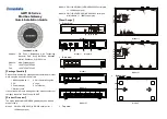
Model II Model III
Left view, right view
Model I
Model II Model III
1.
10/100Base-T(X) Ethernet port
2.
Restoring factory setting button
3.
Serial port transmission data indicators
4.
Serial port receiving data indicators
5.
Copper port connection indicator
6.
Running status indicator
7.
Power indicator
8.
Terminal block 1 for power input
9.
Grounding screw
10.
DIP switch
11.
Console Port
12.
RS-232 serial port
13.
Terminal block 2 for power input
14.
RS-485/422/232 serial port
15.
RS-485/422 serial port
16.
Foot pad
17.
Mounting
18.
Wall-mounting location hole
【
Mounting Dimension
】
Unit: mm
Model I
Model II Model III
Note Before Mounting:
Don't place or install the device in area near water or
moist, keep the relative humidity of the device
surrounding between 5%~95% without condensation.
Before power on, first confirm the supported power
supply specification to avoid over-voltage damaging the
device.
The device surface temperature is high after running;
please don't directly contact to avoid scalding.
【
Wall-mounted Device Mounting
】
Model I
Step 1
Adopt M3 screw to install the left/right mounting
board on the device backboard.
Step 2
Place the device on the wall as reference or
reference installation dimension; mark 2 bolt
positions on the wall.
Step 3
Attach the equipment to the marked wall and
tighten it with M4 screws to the marked position.
Mounting ends.
Model II Model III
Step 1
Adopt M3 screw to install the left/right mounting
board on the device backboard.


