3M™ MicroTouch™ Controller RX141 Reference Guide
21
3M Touch Systems, Inc. Proprietary Information
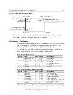
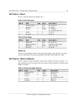
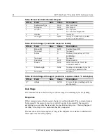
Table 11. Set Feature - Calibration
Offset
Field
Size
Value
Description
0
bmRequestType
1
0x21
Host to device
1 bRequest 1
0x09
Set
Report
2
wValue
2
0x0303
03 = Feature
03 = Feature Report ID
4 wIndex
2
0 Always
0
6 wLength 2
8 Always
8
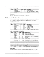
Table 12. Data Stage
Offset
Field
Size
Value
Description
0
bReport ID
1
0x21
Host to device
1 bmReport
Subtype
1 0x04
Set
Report
2
bCalType
1
0xXX
0x03 = 3-point calibration (C3)
3 Not
used
5
0 Not
used
Response
The device stalls endpoint 0 if the command cannot be processed successfully. The
request cannot be processed if an invalid calibration type is given in the wValue field.
During the calibration process, the calibration software polls the Get Status command to
monitor the progress of the calibration.
The calibration will fail if the three calibration points do not fall within certain bounds
established by the firmware. These bounds require that the 3 calibration points be in
correct quadrants of the sensor.
Calibration software can abort the calibration process with a Reset Request.
During the calibration process, the controller automatically determines display orientation
and connector pinouts. This information is saved in the controller non-volatile memory.
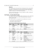
Table 13. Calibration Response
Command
Status Byte
Description
0 Calibration
Failed
1
Controller is waiting for a touch in the lower left corner.
Calibration software paints a target in the lower left corner.
2
Controller is waiting for a touch in the upper right corner.
Calibration software paints a target in the upper right corner.
3
Calibration completed successfully.
6
Controller is waiting for a touch in the upper left corner.
Calibration software paints a target in the upper left corner.
This command corrects for display orientation and pinout variations. This information


