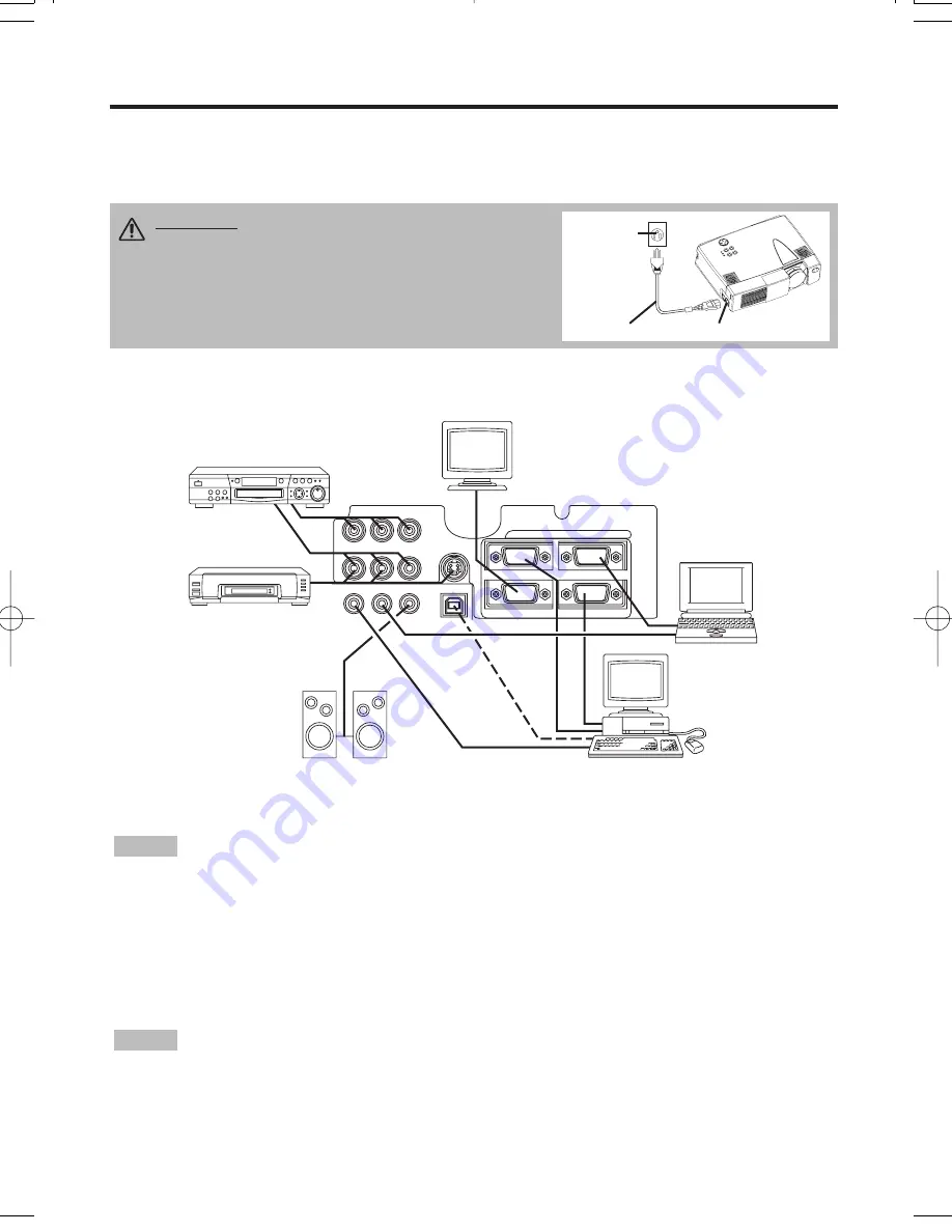
3M Multimedia Projector MP8749 User Manual Download Page 8

AUDIO IN

COMPONENT VIDEO

VIDEO IN

S-VIDEO IN

AUDIO
IN

AUDIO OUT

1

1

2

2

USB

RGB  IN

RGB  OUT

CONTROL

Example of system setup

S-Video Tape
Recorder 

Computer

(notebook type)

• When connecting with notebook computer, set to valid the RGB external image output

(setting CRT display or simultaneous display of LCD and CRT). Please read instruction manual of
the notebook for more information.

Plug & Play

This projector is VESA DDC 1/2B compatible. Plug & play is possible by connecting to a computer
that is VESA DDC (Display Data Channel) compatible.
Please use this function by connecting the accessory RGB cable with RGB IN 1 terminal (DDC
1/2B compatible). Plug & play may not operate by other connecting.

• Plug & play is a system configured with peripheral equipment including a computer and

display, and an operating system.
• This projector is recognized as a plug & play monitor. Use the standard display drivers. 
• Plug & play may not operate by the computer to connect. Use the RGB IN 2 terminal if plug &
play does not operate correctly.

NOTE

NOTE

ENGLISH-8

II

II

N

N

N

N

S

S

S

S

T

T

T

T

A

A

A

A

L

L

L

L

L

L

L

L

A

A

A

A

T

T

T

T

II

II

O

O

O

O

N

N

N

N


((

((

c

c

c

c

o

o

o

o

n

n

n

n

tt

tt

ii

ii

n

n

n

n

u

u

u

u

e

e

e

e

d

d

d

d

))

))

Power Connection

Use the correct one of the enclosed power cords depending on the power outlet to be used.
Connect the AC inlet of the projector to the power outlet firmly by the power cord.

AC Inlet

Power Cord

Power 

outlet

Speaker with
amplifier

Display
Monitor

CAUTION • Be carful in handling the power
cord according to instructions of the

accompanying manual "SAFETY INSTRUCTIONS"
and this manual.
• Connect the power cord firmly. Avoid using a
loose, unsound outlet or contact failure.

Computer

(desktop type)

DVD Player

01CP-X380W  01.12.11 4:11 PM  ページ 8

Summary of Contents for Multimedia Projector MP8749

Page 1: ...nu 16 Table 9 OSD Message 20 Table 10 Indicator Message 21 Table 11 Symptom 22 Table 12 Specifications 23 For TECHNICAL and REGULATORY NOTICE see the end of this manual The information in this manual...

Page 2: ...he package If anything is missing please contact your dealer Keep the original packing material for future reshipment NOTE Projector MP8749 Multimedia Projector Operator s Guide MP8749 Projecteur mult...

Page 3: ...tton Filter Cover Air Filter and Intake for the Cooling Fan Rear Foot Adjuster INPUT Button LAMP Indicator TEMP Indicator POWER Indicator RESET Button MENU Button Ventilation Openings exhaust REAR RIG...

Page 4: ...n Used to operate the mouse shift function MAGNIFY Button BLANK Button RGB Button MOUSE RIGHT Button Used to click the right mouse button RESET Button Used to click the right mouse button FREEZE Butto...

Page 5: ...y oriented as indicated in the remote control transmitter Incorrect orientation could cause battery cracking or leakage which could result in personal injury or pollution of the surrounding environmen...

Page 6: ...screen 10 Table 1 Installation Reference a CAUTION Install the projector in a suitable environment according to instructions of the accompanying manual SAFETY INSTRUCTIONS and this manual When you fix...

Page 7: ...les which are included with the projector or specified Cabling Refer to the table below for connecting each terminal of the projector to each device Table 2 Cabling Function Terminal Cable RGB input R...

Page 8: ...ncluding a computer and display and an operating system This projector is recognized as a plug play monitor Use the standard display drivers Plug play may not operate by the computer to connect Use th...

Page 9: ...le the POWER indicator is blinking 2 The system assumes the Standby mode when cooling is complete and the POWER indicator ceases blinking and changes to orange Check that the indicator is orange and s...

Page 10: ...y the icon is extinguished and the POSITION mode is cleared automatically and buttons may operate as the mouse control button Refer to page 4 RESET Initialise Each Item Select an item and press the RE...

Page 11: ...Stop Press the MENU button The menu display is terminated automatically after approximately 10 seconds of inactivity MENU SELECT Select Menu Type Press the MENU SELECT button Allows the user to select...

Page 12: ...E COLOR BAL R COLOR BAL B ASPECT 0 1 1 0 0 0 SETUP INPUT OPT IMAGE Table 4 Setup Menu Item Description RGB VIDEO S VIDEO COMPONENT 480i 575i 480P 720P 1080i BRIGHT Dark Light CONTRAST Weak Strong V PO...

Page 13: ...ly with some input signals Pressing the AUTO button in this case may correct this problem This function is the same as for the AUTO function in Basic operation RGB Displays RGB Input Frequency Display...

Page 14: ...en Color Select color with the button The image is cleared and the entire screen is displayed in the selected color when BLANK mode is set with BLANK ON or when there is no signal for 5 minutes MIRROR...

Page 15: ...OFF Set AUTO OFF Set 1 99 minutes with the button The system automatically enters the standby mode when a signal is not received for the set time Clear AUTO OFF Select STOP 0 min with the button When...

Page 16: ...ted color MIRROR Select Mirror Status Select the mirror status with the button START UP Setup Initial Screen Display Select the TURN ON with the button Clear Initial Screen Display Select the TURN OFF...

Page 17: ...Before replacing the lamp switch power OFF wait approximately 20 minutes and switch power ON again If the LAMP indicator is still red replace the lamp NOTE WARNING For disposal of used lamp treat acc...

Page 18: ...he Lamp Timer Reset the lamp timer after replacing the lamp When the lamp has been replaced after the LAMP indicator is red or the CHANGE THE LAMP message is displayed complete the following operation...

Page 19: ...h CAUTION Switch power OFF and remove the power cord from the power outlet before beginning maintenance work Please read the separate SAFETY INSTRUCTIONS thoroughly to ensure that maintenance is perfo...

Page 20: ...THE POWER WILL TURN OFF AFTER 0 hr The usage time of lamp is about to reach Power will be switched OFF in a few minutes 2 Switch power OFF immediately and replace the lamp as shown in P 17 18 Lamp Al...

Page 21: ...s red Blinks red Turns off Lamp or lamp cover is not found or hasn t been fitted in correctly Switch power OFF and wait for 45 minutes until the equipment cools Check fitting of the lamp and lamp cove...

Page 22: ...but no audio The projector is not correctly connected Connect correctly 7 8 The volume is set to minimum Press VOLUME on the remote control or display the menu screen and adjust the volume 11 15 Mute...

Page 23: ...ite sync TTL level D sub 15 pin shrink jack 2 AUDIO IN 1 200mVrms 50 k max 3 0Vp p Stereo mini jack 2 Video signal input VIDEO IN 1 0Vp p 75 terminator RCA jack S VIDEO IN Brightness signal 1 0Vp p 75...

Page 24: ...tter 78 8118 8935 7 Handle 78 8118 8673 4 Not Included with Basic Packet Part Number Ceiling Mount 78 6969 9261 5 Adjustable Height Suspension 78 6969 8312 7 Shipping Case 78 6969 9259 9 Soft Carry Ca...

Reviews: