background image

ENGLISH-5

ENGLISH

INSTALLATION

INSTALLATION

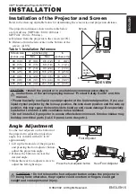
Installation of the Projector and Screen

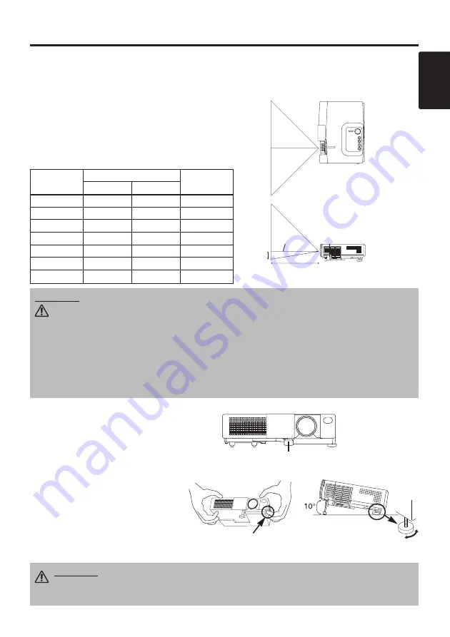
Refer to the drawing and table below for determining the screen size and projection distance.

Angle Adjustment

Use the foot adjusters on the bottom of
the projector to adjust the projection
angle. It is variable within 0˚ to 10˚
approximately.
1. Lift up the front side of the projector,

and pressing the foot adjuster button,
adjust the projection angle.

2. Release the button to lock at the

desired angle.

3. Make the rear foot adjuster screw to

adjust the left-right slope.

The projection distances shown in the table below
are for full size (MP7640i : 800 x 600 dots /
MP7740i : 1024 x 768 dots).

a

: Distance from the projector to the screen. (±10%)

b

: Distance from the lens center to the bottom of the

screen. (±10%)

Table 1. Installation Reference

Screen

CAUTION • Install the projector in a suitable environment according to

instructions of the accompanying manual “Product Safety Guide” and this
manual.

• Please basically use liquid crystal projector at the horizontal position. If you use
liquid crystal projector by the lens up position, the lens down position and the side up
position, this may cause the heat inside to build up and cause damage. Be especially
careful not to install it with ventilation holes blocked.
• Do not install LCD projector in smoke effected environment. Smoke residue may
buildup on critical parts (i.e.LCD panel, Lens Assy etc.).

CAUTION • Do not release the foot adjuster button unless the projector is
being held; otherwise, the projector could overturn or fingers could get

caught and cause personal injury.

TOP VIEW

SIDE VIEW

a

b

Foot Adjuster

Press the foot adjuster button

Rear 

Foot Adjuster

Lens
center

Screen size
[inches (m)]

a

[inches (m)]

b

[inches (cm)]

Min.

Max.

40  (1.0)

37  (0.9)

46  (1.2)

3     (8.7)

60  (1.5)

57  (1.5)

69  (1.8)

5   (13.1)

80  (2.0)

77  (1.9)

93  (2.4)

7   (17.4)

100  (2.5)

96  (2.4)

116  (2.9)

9   (21.8)

120  (3.0)

116  (2.9)

139  (3.5)

10   (26.1)

150  (3.8)

145  (3.7)

174  (4.4)

13   (32.7)

200  (5.0)

194  (4.9)

233  (5.9)

17   (43.5)

3M™ Multimedia Projector MP7740i 

© 3M 2002.  All Rights Reserved.

Summary of Contents for MP7740I

Page 1: ...handbuch MP7740i Proyector de Multimedia Gu a del usuario MP7740i Proiettore Multimediale Guida dell operatore MP7740i Multimedia Projector Gebruiksaanwijzing MP7740i Projector dos Multimedia Guia da...

Page 2: ...MP8775iPSG 02 1 21 4 07 PM 48 3M Multimedia Projector MP7740i...

Page 3: ...OSD Message 19 Table 10 Indicator Message 20 Table 11 Symptom 21 Table 12 Specifications 22 For TECHNICAL see the end of this manual The information in this manual is subject to change without notice...

Page 4: ...future reshipment NOTE Projector Power Cord US Type Power Cord UK Type Power Cord Europe Type VGA Cable Stereo Mini Cable VIDEO STANDBY ON KEYSTONE POSITION FREEZE MAGNIFY VOLUME AUTO OFF BLANK MENU S...

Page 5: ...ton INPUT Button STANDBY ON Button Foot Adjuster Button Air Filter and Intake for the Cooling Fan Speaker Rear Foot Adjuster LAMP Indicator TEMP Indicator POWER Indicator MENU Button Ventilation Openi...

Page 6: ...e reverse side of the remote controller 2 Pinch the groove and pull out battery holder as the drawing right 3 Remove the worn battery 4 Install the new battery with side facing 5 Push in and click the...

Page 7: ...he accompanying manual Product Safety Guide and this manual Please basically use liquid crystal projector at the horizontal position If you use liquid crystal projector by the lens up position the len...

Page 8: ...ct connecting could result in fire or electrical shock Please read this manual and the separate Product Safety Guide Before connecting turn off to all devices to be connected except for the USB cable...

Page 9: ...omputer display and an operating system This projector is recognized as a plug play monitor Use the standard display drivers Plug play may not operate by the computer to connect NOTE NOTE I I I IN N N...

Page 10: ...indicator is blinking 2 The system assumes the Standby mode when cooling is complete and the POWER indicator ceases blinking and changes to orange Check that the indicator is orange and set the Power...

Page 11: ...e Position Adjustment Press the RESET button and the POSITION mode This function is valid only when RGB signal is input Valid except for the VOLUME LANGUAGE H PHASE and WIHSPER MAGNIFY Set MAGNIFY Mod...

Page 12: ...Blank mode The screen color is as set in BLANK on the Image menu MENU ON OFF Menu Display Start Stop Press the MENU button The menu display is terminated automatically after approximately ten seconds...

Page 13: ...0 1 1 0 0 0 SETUP INPUT OPT IMAGE Table 4 Setup Menu Item Description RGB VIDEO S VIDEO COMPONENT 480i 575i 480P 720P 1080i BRIGHT Dark Light CONTRAST Weak Strong V POSIT Down Up H POSIT Left Right H...

Page 14: ...ntal and vertical sync signal frequencies for RGB input Valid only at RGB input VIDEO Operation Start Stop Press the button Select Video Signal Type Select the signal type with the and buttons Select...

Page 15: ...ted color when BLANK mode is set with BLANK ON or when there is no signal for 5 minutes MIRROR Operation Start Stop Press the button Select Mirror Status Select mirror status with and buttons START UP...

Page 16: ...tes with the and buttons The system automatically enters the standby mode when a signal is not received for the set time Clear AUTO OFF Select STOP 0 min with the button When STOP is selected the syst...

Page 17: ...tial Screen Display Select the TURN ON with the button Clear Initial Screen Display Select the TURN OFF with the button Note that if TURN OFF is selected the blank screen is displayed in blue when the...

Page 18: ...OFF wait approximately 20 minutes and switch power ON again If the LAMP indicator is still red replace the lamp NOTE WARNING For disposal of used lamp treat according to the instruction of community...

Page 19: ...er Reset the lamp timer after replacing the lamp When the message of CHANGE THE LAMP THE POWER WILL TURN OFF AFTER 0 hr is displayed complete the following operation within 10 minutes The power will b...

Page 20: ...d a neutral detergent and wipe dry with a soft dry cloth CAUTION Switch power OFF and remove the power cord from the power outlet before beginning maintenance work Please read the separate Product Saf...

Page 21: ...hr The usage time of lamp is about to reach Power will be switched OFF in a few minutes 2 Switch power OFF immediately and replace the lamp as shown in P 17 18 Lamp Always reset the lamp timer after...

Page 22: ...mp cover is not found or hasn t been fitted in correctly Switch power OFF and wait for 45 minutes until the equipment cools Check fitting of the lamp and lamp cover and switch power ON again Contact y...

Page 23: ...o audio The projector is not correctly connected Connect correctly 6 7 The volume is set to minimum Press VOLUME on the remote control or display the menu screen and adjust the volume 10 14 Mute is tu...

Page 24: ...215 D mm Weight mass MP7640i 2 4 kg MP7740i 2 5 kg RGB signal input RGB IN Video Analog 0 7Vp p 75 terminator positive H V sync TTL level positive negative Composite sync TTL level D sub 15 pin shrink...

Page 25: ...e control 78 8118 8909 2 Not Included with Basic Packet Part Number Ceiling mount 78 6969 9206 0 Adjustable height suspension 78 6969 8312 7 Shipping case 78 6969 9204 5 Soft carry case 78 6969 9203 7...

Page 26: ...2 Brightness 1 0Vp p 75 terminator 3 Ground 4 Ground Signal Connector Pin Assignment 1 D sub 15 pin Shrink Connector RGB IN 1 2 3 4 5 6 7 8 9 10 11 12 13 14 15 Pin No Signal Pin No Signal 1 Video inp...

Page 27: ...74 5 Mac16 mode Zoom out Zoom in 1024 768 48 4 60 0 VESA XGA 60Hz Zoom out 1024 768 56 5 70 1 VESA XGA 70Hz Zoom out 1024 768 60 0 75 0 VESA XGA 75Hz Zoom out 1024 768 68 7 85 0 VESA XGA 85Hz Zoom ou...

Page 28: ...6 SVGA 56Hz 2 0 3 6 22 2 0 7 SVGA 60Hz 3 2 2 2 20 0 1 0 SVGA 72Hz 2 4 1 3 16 0 1 1 SVGA 75Hz 1 6 3 2 16 2 0 3 SVGA 85Hz 1 1 2 7 14 2 0 6 Mac 16 mode 1 1 3 9 14 5 0 6 XGA 60Hz 2 1 2 5 15 8 0 4 XGA 70Hz...

Page 29: ...read the instruction manuals of the devices to be connected In the case of notebook type computers with an internal pointing device the mouse control function will not work unless the internal pointi...

Page 30: ...GND DSR RTS CTS RI 1 2 3 4 5 6 7 8 9 RS 232C jack D sub 9 pin Projector Computer Communications setting 19200bps 8N1 1 Protocol Consist of header 7 bytes command data 6 bytes 2 Header BE EF 03 06 00 C...

Page 31: ...06H to the computer Decreasing the projector setting value Decrement command 1 The computer sends the decrement code Header Command data 05H 00H type 2 bytes 00H 00H to the projector 2 The projector d...

Page 32: ...01 00 Get BE EF 03 06 00 B0 D2 02 00 02 30 00 00 Menu Color Set Red BE EF 03 06 00 7F D3 01 00 03 30 00 00 Orange BE EF 03 06 00 EF D2 01 00 03 30 01 00 Green BE EF 03 06 00 1F D2 01 00 03 30 02 00 Bl...

Page 33: ...C4 D0 06 00 09 70 00 00 Color Reset Execute BE EF 03 06 00 80 D0 06 00 0A 70 00 00 Tint Reset Execute BE EF 03 06 00 7C D1 06 00 0B 70 00 00 Keystone_V Reset Execute BE EF 03 06 00 08 D0 06 00 0C 70 0...

Page 34: ...rement BE EF 03 06 00 0E D2 05 00 07 20 00 00 Aspect Set 4 3 Full BE EF 03 06 00 9E D0 01 00 08 20 00 00 16 9 BE EF 03 06 00 0E D1 01 00 08 20 01 00 Small BE EF 03 06 00 FE D1 01 00 08 20 02 00 Get BE...

Page 35: ...00 FE 74 01 00 00 22 08 00 N PAL BE EF 03 06 00 0E 71 01 00 00 22 07 00 Get BE EF 03 06 00 0D 73 02 00 00 22 00 00 HDTV Set 1080i BE EF 03 06 00 F2 73 01 00 05 22 00 00 1035i BE EF 03 06 00 62 72 01 0...

Page 36: ...se Before operating this machine please read this entire manual thoroughly The 3MTM Multimedia Projectors are designed built and tested for use indoors using 3M lamps 3M ceiling mount hardware and nom...

Reviews: