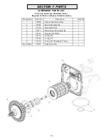
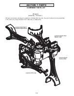
3M MCWS075ME Installation And Operating Instructions Manual Download Page 16

Drive Assembly

Remove the valve cover to access the drive assembly.

WARNING:

 Disconnect the power source plug (black wire) 

from the PC board prior to disconnecting the motor or water 
meter plugs from the PC board. The power source plug 
connects to the four-pin jack. The motor plug connects to the 
two-pin jack on the left-hand side of the PC board. The water 
meter plug (grey wire) connects to the three-pin jack on the far 
right-hand side of the PC board.

The PC board can be removed separately from the drive
bracket but it is not recommended. Do not attempt to remove 
the display panel from the PC board. Handle the board by the 
edges. To remove the PC board from the drive bracket, 
unplug the power, water meter and motor plugs from the PC 
board. Lift the middle latch along the top of the drive bracket 
while pulling outward on the top of the PC board. The drive 

EUDFNHWKDVWZRSODVWLFSLQVWKDW¿WLQWRWKHKROHVRQWKHORZHU

edge of the PC board. Once the PC board is tilted about 45° 
from the drive bracket it can be lifted off of these pins. To
reinstall the PC board, position the lower edge of the PC 
board so that the holes in the PC board line up with the 
plastic pins. Push the top of the PC board towards the valve 
until it snaps under the middle latch, weave the power and 
water meter wires into the holders and reconnect the motor,
water meter and power plugs. 

The drive bracket must be removed to access the drive cap
assembly and pistons or the drive gear cover. It is not neces-
sary to remove the PC board from the drive bracket to 
remove the drive bracket. To remove the drive bracket, start 
by removing the plugs for the power source and the water 
meter. Unweave the wires from the side holders. Two tabs on 
the top of the drive back plate hold the drive bracket in place. 
Simultaneously lift the two tabs and gently ease the top of the 
drive bracket forward.The lower edge of the drive bracket 
has two notches that rest on the back plate. Lift up and 
outward on the drive bracket to disengage the notches.

To reassemble, seat the bottom of the drive bracket so the
notches are engaged at the bottom of the drive back plate. 
Push the top of the drive bracket toward the two latches. The
drive bracket may have to be lifted slightly to let the threaded 
piston rod pass through the hole in the drive bracket. Main-
tain a slight engaging force on top of the drive bracket while 

GHÀHFWLQJWKHEUDFNHWVOLJKWO\WRWKHOHIWE\SUHVVLQJRQWKH

side of the upper right corner. This helps the drive gears 
mesh with the drive cap assembly. The drive bracket is prop-
erly seated when it snaps under the latches on the drive back 
plate. If resistance is felt before latching, then notches are 
not fully engaged, the piston rod is not in hole, the wires are 
jammed between the drivebracket and drive back plate, or 
the gear is not engaging the drive cap assembly.  To inspect 
the drive gears, the drive gear cover needs to be removed. 
Before trying to remove the gear cover, the drive bracket 
must be removed from the drive back plate. (Refer to the 

proceeding instructions regarding removing the drive bracket 
from the drive backplate. The drive gear cover can be 
removed from the drive bracket without removing the motor 
or the PC board.)  The drive gear cover is held in place on the 
drive bracket by three clips. The largest of the three clips is 
always orientated to the bottom of the drive bracket. With the 
PC board facing up, push in and down on the large clip on the 
drive gear cover. Handle the cover and the gears carefully so 
that the gears do not fall off of the pegs in the cover. 

Replace broken or damaged drive gears. Do not lubricate
any of the gears. Avoid getting any foreign matter on the 

UHÀHFWLYH FRDWLQJ EHFDXVH GLUW RU RLOV PD\ LQWHUIHUH ZLWK

pulse counting. 

The drive gear cover only fits on one way, with the large clip
orientated towards the bottom. If all three clips are outside of 
the gear shroud on the drive bracket the drive gear cover 
slips easily into place.

The drive bracket does not need to be removed from the
drive plate if the motor needs to be removed. To remove the 
motor,disconnect the power and motor plugs from the jacks 
on the PC board. Move the spring clip loop to the right and 
hold. Rotate the motor at least a ¼ turn in either direction so 
the wires are vertical (up & down) before gently pulling on 
the wire connectors to remove the motor. Pulling directly on 
the wires without rotating the motor may break the wires off 
the motor. 

Replace the motor if necessary. Do not lubricate the motor or 
the gears. To reinstall the motor, move the spring clip loop to 
the right and hold. Gently turn the motor while inserting so 
that the gear on the motor meshes with the gears under the 
drive gear cover. Release the spring clip loop and continue 
to rotate the motor until the wires are horizontal and the 
motor housing engages the small plastic bulge inside the 
drive bracket motor retainer. Reconnect the motor plug to 
the two-pronged jack on the lower left hand side of the PC 
board. If the motor will not easily engage with the drive gears 
when reinstalling, lift and slightly rotate the motor before 
reinserting. Reconnect the power.

Replace the valve cover. After completing any valve mainte-
nance, press and hold NEXT and REGEN buttons for 3 
seconds or unplug power source jack (black wire) and plug 
back in. This resets the electronics and establishes the 

VHUYLFHSLVWRQSRVLWLRQ7KHGLVSOD\VKRXOGÀDVKDOOZRUGLQJ
WKHQÀDVKWKHVRIWZDUHYHUVLRQHJDQGWKHQUHVHWWKH

valve to the service position. 

5-3

SECTION 5:  CONTROL VALVE SERVICE INSTRUCTIONS

Summary of Contents for MCWS075ME

Page 1: ...usco IN 46723 U S A Installer Please leave with homeowner CAUTION Damage to the system can occur including possible mineral tank structure failure resulting in a water leak if system is subjected to a...

Page 2: ...te disinfection before or after the system To reduce the risk associated with a hazardous voltage due to installation on a home system that requires use of the cold water system as a safety ground If...

Page 3: ...ually trouble free service Before starting the instal lation we suggest you read this manual all the way through for an overview and then follow the installation steps in the proper sequence IMPROPER...

Page 4: ...e items The pumping rate of thewellpumpmustbesufficienttoaccommodatethese items plus the backwashing requirements of the water softener Consultyourdealerforalternativeinstructions if the pumping rate...

Page 5: ...Y SECONDARY TANK CHECK VALVE PRESSURE OUTPUT SOLENOID VALVE TO 110 V PRIMARY TANK PRESSURE PRESSURE SWITCH TANK PRESSURE OUTPUT TO 110 V TREATED WATER TREATED WATER WELL WATER RAW SOLENOID VALVE CHECK...

Page 6: ...WELL SAFETY BRINE VALVE ASSEMBLY BRINE LINE ELBOW INJECTOR COVER OFF OFF OFF OFF Step 7 Attach DRAIN LINE to DRAIN LINE FITTING To preventbackpressurefromreducingflowratebelow minimumrequiredforbackwa...

Page 7: ...may be necessary when unusual operating conditions exist such as high concentrations of iron mang 2 3 Some areas prohibit the use of flexible drain lines Check with local code officials prior to inst...

Page 8: ...salt fill to brine tank and one 1 cup eight ounces of unscented laundry bleach to the brine well Step 17 Put your new water softener through a complete regeneration to sanitize the system prior to use...

Page 9: ...t itself If an extended power outage occurs the time of day will flash on and off which in dicated the time of day should be reset The system will remember the rest If the word error and a number are...

Page 10: ...ay shows day IRU HVWHUGD DQG DVKHV WKH number of gallons treated yesterday Pressing the button will show day 2 which would be the day before yesterday and flashes the number of gallons treated on ORZ...

Page 11: ...p Gallons total used since start up This display shows the total gallons This display shows the total days since startup Press the NEXT button to go to the next step Press REGEN to return to previous...

Page 12: ...y To initiate a manual regeneration at the present delayed regeneraton time press and release REGEN The words REGEN TODAY will flash on the display to indicate that the system will regenerate at the p...

Page 13: ...once a year if rock salt is used with other types of salt approximately once every other year PREVENTINGIRON FOULINGOFMINERALBED If iron is present in the water supply the softener mineral bedwilleve...

Page 14: ...Check piston and spacer stack valve assembly c High drive forces on piston c Replace piston s and spacer stack assembly d Control valve piston not in home d Press NEXT and REGEN for 3 position second...

Page 15: ...Replace main or regenerant piston a AC Adapter unplugged a Connect AC Adapter b No electric power at outlet b Repair outlet or use working outlet c Broken drive gear or c Replace drive gear or drive...

Page 16: ...are not fully engaged the piston rod is not in hole the wires are jammed between the drivebracket and drive back plate or the gear is not engaging the drive cap assembly To inspect the drive gears th...

Page 17: ...OXJ SRZHU VRXUFH MDFN EODFN ZLUH DQG SOXJ back in This resets the electronics and establishes the service SLVWRQ SRVLWLRQ 7KH GLVSOD VKRXOG DVK DOO ZRUGLQJ WKHQ DVK WKH VRIWZDUH YHUVLRQ H J DQG WKHQ U...

Page 18: ...UHPRYH LW IURP WKH VKDIW R QRW XVH D ZLUH EUXVK WR FOHDQ WKH WXUELQH LSH ZLWK D FOHDQ FORWK RU FKHPLFDOO FOHDQ LQ GLOXWH VRGLXP ELVXO WH RU YLQHJDU 7KH WXUELQH FDQ EH LPPHUVHG LQ WKH FKHPLFDO R QRW L...

Page 19: ...hite spots on glassware and dark surfaces 8 Low water pressure low flow rate 9 Rotten egg smell from hot water ONLY 10 Rotten egg smell from both hot and cold water 11 Lossofresinthrough drain line SO...

Page 20: ...3 8 h s a w k c a B 3 3 3 3 4 e s n i R d i p a R 3 1 5 3 l l i f e R e n i r B 51 5 51 7 52 11 53 Approximate Total Time 84 61 63 65 69 T P N 1 T P N 1 T P N 1 T P N 1 T P N 1 e z i S t e l t u O t...

Page 21: ...0P H 075P H 10P X2 H 10P X3 Brine Line Tubing 13000X 13000X 13000X 13000X 13000X Brine Tank Complete Brine Tank Complete w Extension Kit BT1534X BT1534X BT1534X BT1534X EXT BTCS33BK Overflow Fitting B...

Page 22: ...ption 1 Assembly r e v o C t n o r F 1 0 5 7 1 3 V 1 1 r o t o M 1 0 7 0 1 3 V 2 3 V3106 01 Drive Bracket Spring Clip 1 1 oard B C P 8 0 1 3 V 4 3 6 3 x 2 1 r a e G e v i r D 0 1 1 3 V 5 1 r e v o C r...

Page 23: ...V3005 Spacer Stack Assembly 1 1 1 1 p Assembly a C e v i r D 4 0 0 3 V 2 1 e t a l P k c a B e v i r D 8 7 1 3 V 3 4 V3011 Piston Down ow Assembly 1 5 V3174 Regenerant Piston 1 8 2 2 g n i r O 5 3 1 3...

Page 24: ...c e j n I 6 7 1 3 V 1 1 5 3 1 g n i r O 2 5 1 3 V 2 1 1 n e e r c S r o t c e j n I 7 7 1 3 V 3 4 V3010 1Z Injector ASY Z Plug 5 V3010 1B INJECTOR ASY B BROWN V3010 1C INJECTOR ASY C VIOLET V3010 1E I...

Page 25: ...a r D 1 p i l C g n i k c o L w o b l E 5 1 6 4 H 2 1 1 8 3 t r e s n i e b u t y l o P 6 P P C J 3 1 8 3 t u N K L B P 6 G P C J 4 1 8 3 p a C w o b l E 3 1 6 4 H 5 1 9 1 0 g n i r 0 3 6 1 3 V 6 1 BL...

Page 26: ...olytube insert 5 8 PKP10TS8 BULK 2 3 V3192 Nut Drain Elbow 4 V3158 01 Drain Elbow Male 1 1 1 1 1 9 1 0 g n i r O 3 6 1 3 V 5 6 V3159 01 DLFC Retainer Assembly 7 One DLFC must be used if WWLQJ LV XVHG...

Page 27: ...Description 1 C Q 1 t u N 1 5 1 3 V 1 1 Meter Assembly includes drawing 3 4 3 0 0 3 V 2 1 e n i b r u T 1 0 8 1 1 3 V 3 1 5 1 2 g n i r 0 5 0 1 3 V 4 1 Meter Plug Assembly 1 0 3 0 0 3 V 5 3 4 5 1 2 7...

Page 28: ...ect 2 2 Split Ring 0 5 1 3 V 2 2 2 5 1 2 g n i R O 5 0 1 3 V 3 4 V3 Fitting 3 4 Brass Sweat Assembly Quantity Order No V3007 05 Description Fitting 1 1 4 Plastic Male NPT Assembly Drawing No Order No...

Page 29: ...4 1 3 V 4 2 6 4 1 3 V 5 2 7 4 1 3 V 6 7 Bypass Rotor Seal Retainer 2 2 5 3 1 g n i r O 2 5 1 3 V 8 2 2 1 1 g n i r O 5 5 1 3 V 9 2 4 1 2 g n i r O 6 5 1 3 V 0 1 V3191 01 Vertical Adapter Assembly Orde...

Page 30: ...93 01 Although no tools are necessary to assemble or disassemble the valve the wrench shown in various positions on the valve may be purchased to aid in assembly or disassembly 7 10 SECTION 7 PARTS CO...

Page 31: ...l be to repair at its expense and at no charge to the original purchaser consumer any Product that is actually defective malfunctioning or otherwise in violation of this Warranty If CUNO for any reaso...

Page 32: ...CUNO Aqua Pure and MacCLEAN are trademarks of 3M Company used under license 2006 3M Company All rights reserved...

Reviews: