29
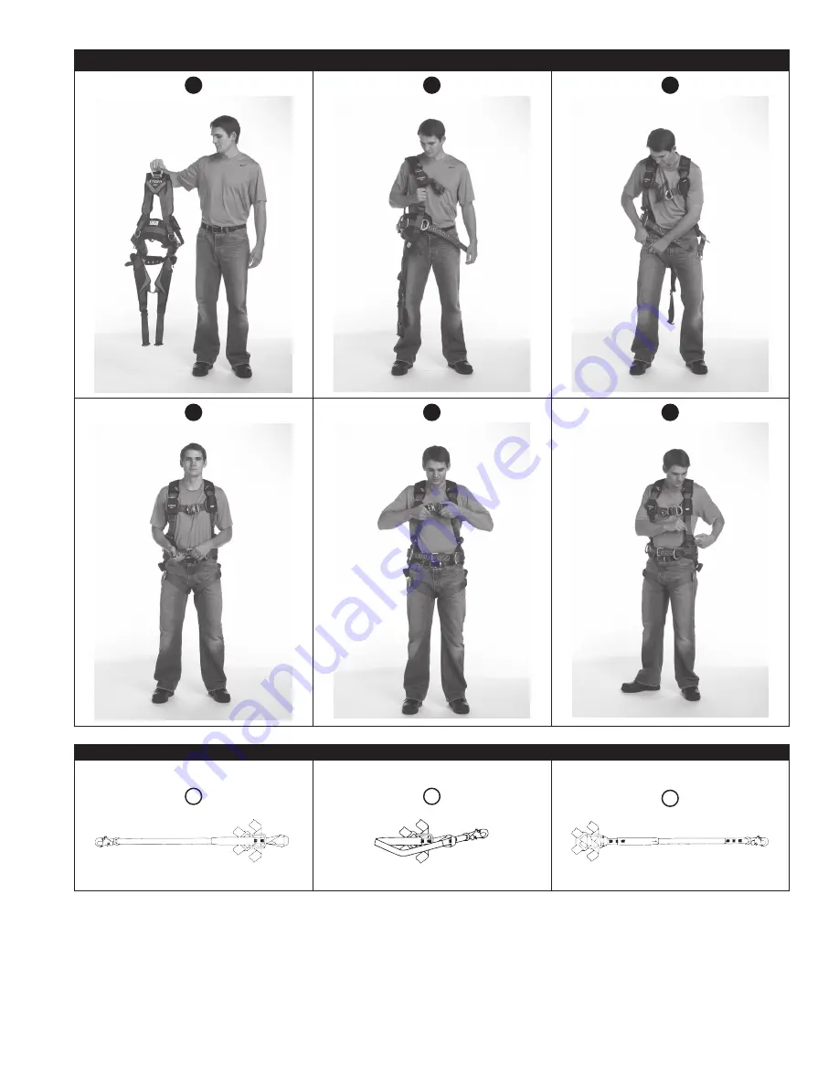
Figure 8 – Mise en place du harnais
1
2
3
4
5
6
Figure 9 – Fixation des longes avec extrémités en boucle
A
B
C
Page 1: ...13 1113214 A 1113215 1113216 1113217 1113218 1113219 C 1113449 1113450 1113451 1113452 1113453 A 1113264 PARK LANYARD HERE SEE INSTRUCTIONS PARK LANYARD HERE SEE INSTRUCTIONS 1 PARK LANYARD HERE SEE I...
Page 2: ...er Attachment Elements Buckles and Adjusters Other Elements Pads 1 13 8 3 2 6 4 C 1 13 4 6 10 3 12 8 2 4 D D 1402125 1402126 1402127 1402128 1402129 E 1402130 1402131 1402132 1402133 1402134 E 8 2 6 4...
Page 3: ...oduct Do not exceed the number of allowable users specified in these instructions Ensure the harness is appropriately sized adjusted donned and worn as described in these instructions Ensure the produ...
Page 4: ...The availability of a specific application is determined by the attachment elements present on your harness as outlined below If your harness has one of the attachment elements specified for an appli...
Page 5: ...l and alloy steel 18 kN 4 000 lbf Tensile Strength 6 Revolver Adjusters Aluminum alloy stainless steel alloy steel and nylon 18 kN 4 000 lbf Tensile Strength Other Elements 7 Suspension Trauma Straps...
Page 6: ...pacity that is less than your harness you must comply with the capacity requirements of your connecting subsystem See the manufacturer instructions for each component of your system for capacity requi...
Page 7: ...size or shape does not allow the connector to fully close and lock or that could cause connector roll out G In a manner that does not allow the connector to align properly while under load 2 8 LANYARD...
Page 8: ...of the web strap C To release Squeeze the Lock Levers on either side of the Receptor Pull the Tab out of the Receptor 2 Tongue Buckles Fasten and adjust the Tongue Buckle by passing the Tongue through...
Page 9: ...9 Figure 6 Buckles 1 CLICK A C B 2 Figure 7 Adjusters 1 B A...
Page 10: ...10 Figure 8 Donning the Harness 1 2 3 4 5 6 Figure 9 Securing Lanyards with Loop Ends A B C...
Page 11: ...Interface Loop X is part of the backplate for certain harness models The Interface Loop serves as a secure connection point for harness interfaces behind the harness straps See Figure 12 for reference...
Page 12: ...12 Figure 10 Straight Pin Interface B A C B C Figure 11 Carabiner Interface B A C E B D A B D 1 2 3 1 3 4 2...
Page 13: ...ating the Trauma Straps PARK LANYARD HERE SEE INSTRUCTIONS PARK LANYARD HERE SEE INSTRUCTIONS A PULL TO DEPLOY 1 DEPLOY BOTH PACKS 2 INSERT HOOK INTO LOOP ON OPPOSITE STRAP 3 PLACE BOTH FEET INTO WEB...
Page 14: ...the owner of this equipment An inspection and maintenance log should be placed near the product or be otherwise easily accessible to users It is recommended that the product is marked with the date of...
Page 15: ...se visit our website www 3m com FallProtection ifu glossary AUTHORIZED PERSON A person assigned by the employer to perform duties at a location where the person will be exposed to a fall hazard COMPET...
Page 16: ...16 Figure 15 RFID Tag Location PARK LANYARD HERE SEE INSTRUCTIONS PARK LANYARD HERE SEE INSTRUCTIONS A XXX A Figure 16 Product Labels A 1 3 2 B 2 3 4 5 6 1 7 8 C 1 2 3 D 1 X X X X XXX A B C D...
Page 17: ...rs Check for pulled or cut stitches Broken stitches may indicate that the harness has been impact loaded and must be removed from service Stitched Impact Indicators Figure 18 Verify all Impact Indicat...
Page 18: ...lly important when using some types of Y style lanyards as some load may be transmitted to the user through the unused lanyard leg if it is not able to release from the harness The lanyard parking att...
Page 19: ...be used solely for Work Positioning The suspension seat attachment elements shall not be used for Fall Arrest Suspension seat attachments are often used for prolonged work activities where the user is...
Page 20: ...1113215 1113216 1113217 1113218 1113219 C 1113449 1113450 1113451 1113452 1113453 A 1113264 PARK LANYARD HERE SEE INSTRUCTIONS PARK LANYARD HERE SEE INSTRUCTIONS 1 PARK LANYARD HERE SEE INSTRUCTIONS...
Page 21: ...e Hanches Dos et paules l ments de fixation Boucles et dispositifs de r glage Autres l ments Coussinets 1 13 8 3 2 6 4 C 1 13 4 6 10 3 12 8 2 4 D D 1402125 1402126 1402127 1402128 1402129 E 1402130 14...
Page 22: ...is s pr cis s dans les pr sentes directives S assurer que le harnais est de taille appropri e ajust enfil et port comme d crit dans les pr sentes directives S assurer que le produit est configur et in...
Page 23: ...d une utilisation sp cifique est d termin e par les l ments de fixation pr sents sur votre harnais comme indiqu ci dessous Si votre harnais poss de l un des l ments de fixation sp cifi s pour une util...
Page 24: ...4 000 lbf 6 Dispositifs de r glage Revolver Alliage d aluminium acier inoxydable alliage d acier et de nylon r sistance la traction de 18 kN 4 000 lbf Autres l ments 7 Sangles contre les chocs orthos...
Page 25: ...s de capacit du sous syst me de connexion Consulter les directives du fabricant de chacun des composants du syst me pour conna tre les exigences de capacit 2 2 SOUS SYST MES DE CONNEXION Les sous syst...
Page 26: ...de se fermer et de se verrouiller compl tement ou qui pourrait provoquer son ouverture G S ils ne permettent pas au connecteur de s aligner correctement alors qu il est sous tension 2 8 FIXATION DE S...
Page 27: ...ne contr le pas le d gagement de la boucle Il contr le uniquement le r glage de la sangle en toile C Pour d gager Serrer les leviers de verrouillage de chaque c t du r cepteur Tirer sur la languette...
Page 28: ...28 Figure 6 Boucles 1 CLIC A C B 2 Figure 7 R glages 1 B A...
Page 29: ...29 Figure 8 Mise en place du harnais 1 2 3 4 5 6 Figure 9 Fixation des longes avec extr mit s en boucle A B C...
Page 30: ...L interface bouche sert de point de raccordement s curis pour les interfaces du harnais derri re les sangles du harnais Voir la figure 12 aux fins de r f rence Pour se connecter l interface boucle l u...
Page 31: ...31 Figure 10 Interface goupille droite B A C B C Figure 11 Interface mousqueton B A C E B D A B D 1 2 3 1 3 4 2...
Page 32: ...ctiver les sangles contre les chocs orthostatiques PARK LANYARD HERE SEE INSTRUCTIONS PARK LANYARD HERE SEE INSTRUCTIONS A PULL TO DEPLOY 1 DEPLOY BOTH PACKS 2 INSERT HOOK INTO LOOP ON OPPOSITE STRAP...
Page 33: ...et d entretien Le propri taire de ce syst me doit conserver la documentation de chaque inspection Un journal d inspection et d entretien doit tre plac proximit du produit ou tre facilement accessible...
Page 34: ...re site Web www 3m com FallProtection ifu glossary PERSONNE AUTORIS E Une personne affect e par l employeur et charg e d ex cuter des travaux un emplacement qui l expose un danger de chute PERSONNE CO...
Page 35: ...ure 15 Emplacement de l tiquette IRF PARK LANYARD HERE SEE INSTRUCTIONS PARK LANYARD HERE SEE INSTRUCTIONS A XXX A Figure 16 tiquettes des produits A 1 3 2 B 2 3 4 5 6 1 7 8 C 1 2 3 D 1 X X X X XXX A...
Page 36: ...s cass es S assurer que les coutures ne pr sentent pas de coupures ou de fils d faits Les coutures bris es peuvent indiquer que le harnais a t soumis une charge d impact et doit tre retir du service I...
Page 37: ...lly important when using some types of Y style lanyards as some load may be transmitted to the user through the unused lanyard leg if it is not able to release from the harness The lanyard parking att...
Page 38: ...be used solely for Work Positioning The suspension seat attachment elements shall not be used for Fall Arrest Suspension seat attachments are often used for prolonged work activities where the user is...
Page 39: ...ALE DU PRODUIT RECOURS LIMIT ET LIMITATION DE RESPONSABILIT GARANTIE CE QUI SUIT REMPLACE TOUTES LES GARANTIES OU CONDITIONS EXPRESSES OU IMPLICITES Y COMPRIS LES GARANTIES OU LES CONDITIONS IMPLICITE...
Page 40: ...4 97 10 00 10 Fax 33 04 93 08 79 70 informationfallprotection mmm com Australia New Zealand 137 McCredie Road Guildford Sydney NSW 2161 Australia Toll Free 1800 245 002 AUS Toll Free 0800 212 505 NZ 3...