Table 1: Major Sections of OSHA 29 CFR 1910.134
Section
Description
A
Permissible Practice
B
Defi nitions
C
Respiratory Protection Devices
D
Selection of Respirators
E
Medical Evaluations
F
Fit Testing
G
Use of Respirators
H
Maintenance and Care of Respirators
I
Breathing Air Quality and Use
J
Identifi cation of Cartridges, Filters, and Canisters
K
Training and Information
L
Program Evaluation
M
Recordkeeping
Assigned Protection Factors
Table 2: Assigned Protection Factors
Type of Respirator
APF
Half Facepiece Negative Pressure Air Purifying Respirator
10
Half Facepiece Supplied Air Respirator (SAR) Continuous Flow
50
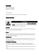
OPERATING INSTRUCTIONS
Unpacking
Inspect the respirator contents for shipping damage and ensure all components are present (Refer to Fig. 26).
The product should be inspected before each use following the procedures in the
Inspection, Cleaning and
Storage
section of these
User Instructions
.
Assembly
3M™ Cartridge, 6000 Series; 3M™ Filter 7093; and 3M™ Cartridge/Filter 7093C Assembly
(Figs. 1 and 2)
1. Align the cartridge or fi lter notch with the small solid bayonet lug on facepiece and push together.
2. Turn cartridge or fi lter clockwise until it is fi rmly seated and cannot be further turned (about 1/4 turn).
3. Repeat with second cartridge or fi lter.
3M™ Filter 2000 Series (Fig. 3)
1. Align opening of fi lter with fi lter attachment on facepiece and push together.
2. Turn fi lter clockwise until it is fi rmly seated and cannot be further turned (about 1/4 turn).
3. Repeat for second fi lter.
Filter Assembly (for 3M™ Filters 5N11 and 5P71)
1. Place fi lter into 3M™ Retainer 501 so printed side of fi lter faces the cartridge.
2. Press cartridge into fi lter retainer. It should snap securely into fi lter retainer. When correctly installed, fi lter
should completely cover face of cartridge (Fig. 4).
3. To replace fi lter, remove retainer by lifting on tab.
In Brazil, the 3M™ Filter 5935BR can be used with the Filter Retainer 501 on the 3M™ Rugged Comfort
Half Facepiece Reusable Respirator, 6500 Series.
3M™ Adapter Assembly 502
1. Align adapter over cartridge. Engage front snap by squeezing front of cartridge and adapter together,
placing thumbs of both hands over top of adapter and fi ngers along bottom sides of cartridge (Fig. 5).
2. Engage back snap by squeezing back side of cartridge and adapter together using the same hand
positions. An audible click should be heard as each snap is engaged (Fig. 6).
3. Place fi lter onto the fi lter holder so fi lter comes into even contact with gasket. Twist clockwise a quarter
turn until it is fi rmly seated and fi lter cannot be turned further. Repeat for second fi lter.
IMPORTANT: The 3M™ Adapter Assembly 502, once installed on a 3M™ Cartridge 6000 Series, is not
to be removed or reused. Removal or reuse may result in leakage, overexposure, sickness or death.
3M™ Filter Adapter 603 Assembly and Filter Attachment
(for 3M™ Filters 5N11 and 5P71)
1. Align notch on edge of 603 adapter with facepiece mark as shown (Fig. 7).
2. Turn adapter 1/4 turn clockwise to stop. To remove adapter, turn 1/4 turn counterclockwise (Fig. 8).
3. Place fi lter into 501 retainer with fi lter printing facing towards the 603 adapter. Snap together and ensure
the fi lter seal is free from creases or gaps (Fig. 9).
In Brazil, the 3M™ Filter 5935BR can be used with the 3M™ Filter Adaptor 603 and the 3M™ Filter
Retainer 501 on the 3M
TM
Rugged Comfort Half Facepiece Reusable Respirator, 6500 Series.
3M™ Dual Airline Respirator Assembly
User must follow Dual Airline Supplied Air Respirator
User Instructions
provided with the 3M™ Dual Airline
Supplied Air Respirators.
Assembly of 3M™ Dual Airline Breathing Tubes
1.
2.
Hold the facepiece in front of you so the 3M logo is facing you. Align the two branches of the breathing
tube over the two bayonet mounts on facepiece (Fig. 10). For SA-1500 or SA-1600 Breathing Tubes, make
sure the 3M logo on breathing tube and on facepiece are both facing towards you. For SA-2500 or
SA-2600 Breathing Tubes, make sure the 3M logo on breathing tube is facing in opposite direction to 3M
logo on facepiece.
Twist each branch of breathing tube clockwise a quarter turn until it is fi rmly seated in the bayonet and
cannot be turned further (Figs. 11 and 12). Do not forcibly overturn as the bayonet could be damaged.
SA-1500/SA-2500 shown.
3. Attach airline to approved air regulators per pressure schedules in dual airline supplied air respirator
User
Instructions.
Assembly of 3M™ Combination Dual Airline Breathing Tubes with Cartridges and/or Filters
The SA-1600 (front-mounted) and SA-2600 (back-mounted) versions of the dual airline breathing tubes allow
use of selected, NIOSH-approved 3M™ Cartridges, 6000 Series, and 3M™ Filters, 2000 Series. For the listing of
approved cartridges and fi lters, reference the NIOSH approval label included with 3M™ Dual Airline Adapter Kits.
1. Remove the inhalation valves from the facepiece as described in the
Replacement Parts Instructions
section of these
User Instructions
and store them so they remain fl at.
2.
3.
Attach SA-1600 or SA-2600 breathing tubes to facepiece per the procedures outlined previously. The
procedure is identical to the attachment of the SA-1500 and SA-2500 models.
Make a selection of cartridges and/or fi lters that meets your respiratory protection requirements, and
attach to the outer bayonets of SA-1600 or SA-2600 breathing tubes (Fig. 13).
4. Don facepiece per procedures outlined in
Donning Respirator
section of these
User Instructions
.
5. After being properly fi t tested, perform a positive and negative pressure user seal check each time the
respirator is donned per procedures outlined in
User Seal Checks
section of these
User Instructions
.
If you cannot achieve a proper fi t, DO NOT enter contaminated area. See your supervisor.
To assemble 3M™ Dual Airline Combination Breathing Tubes with 3M™ Cartridges/Filters, the facepiece
inhalation valves must be removed.
IMPORTANT:
If the facepiece is to be used in air-purifying mode (without using the SA-1600 or SA-2600
breathing tubes), the inhalation valves must be replaced in the facepiece before use.
Using the 3M™ Combination Dual Airline Breathing Tubes without Cartridges and/or Filters
To use the combination dual airline breathing tubes (SA-1600 and SA-2600) without cartridges or fi lters,
attach a 3M™ Bayonet Cap 6880 to each outer bayonet mount on the dual airline breathing tube. When used
as a straight, Type C, continuous fl ow supplied air respirator, the Assigned Protection Factor is 50 times the
PEL, OEL or TLV guidelines for half facepiece respirators.
FITTING INSTRUCTIONS
W
WARNING
Failure to follow these instructions may reduce respirator performance, expose you to
contaminants above the OEL, and
may result in sickness or death.
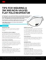
• To help maintain a good seal between the face and the faceseal, the respirator faceseal
must be clear of obstructions at all times. Do not use with beards, facial hair or anything
that prevents direct contact between the face and the respirator faceseal.
These fi tting instructions MUST be followed each time respirator is worn.
Donning Respirator
1. Adjust head cradle size as needed to fi t comfortably on head.
2. Place the respirator over the mouth and nose with one hand.
3. Pull the head harness over the crown of the head with the other hand (Fig. 14). Grasp the bottom straps,
place them at the back of the neck and hook them together (Fig. 15).
4. Pull the ends of the straps to adjust the tightness, beginning with the adjustment points on the head
cradle and then moving to the adjustment points at the back of the neck (Figs. 16 and 17). Do not over-
tighten. Strap tension may be decreased by pushing out on back side of buckles.
5. Perform a positive and/or negative pressure user seal check each time the respirator is donned.
If you cannot achieve a proper fi t, DO NOT enter contaminated area. See your supervisor.
User Seal Checks
Always check the seal of the respirator on your face before entering a contaminated area
according to
the instructions provided below for your specifi c respirator confi guration.
IMPORTANT:
If you cannot achieve a proper seal, DO NOT enter the contaminated area. See your
supervisor. Before assigning any respirator to be worn in a contaminated area, a qualitative or
quantitative fi t test MUST be performed per OSHA Standard 1910.134, CSA Standard Z94.4 or the
Brazil Respiratory Protection Program of the Ministry of Labor.
Positive Pressure User Seal Check
1. Tilt the head up slightly and cover the opening in exhalation valve cover with hand and exhale gently
(Fig. 18). If facepiece bulges slightly and no air leaks are detected between your face and facepiece, a
proper seal has been obtained.