


11
12
Safety Precautions
1. Read all instructions before using this tool. All operators must be fully
trained in its use and aware of these safety rules.
2. The tool RPM should be checked on a regular basis to ensure proper
operating speed.
3. Make sure the tool is disconnected from the air supply. Select a suitable
abrasive and secure it to the disc pad or spindle. Be careful to center the
abrasive on the disc pad.
4. Always wear required safety equipment when using this tool.
5. Always remove the air supply to the tool before fitting, adjusting or
removing the abrasive or disc pad.
6. Always adopt a firm footing and grip and be aware of torque reaction
developed by the tool.
7. Use only 3M approved spare parts.
8. Always ensure the material being worked is firmly fixed to avoid
movement.
9. Check hose and fittings regularly for wear. Do not carry the tool by its
hose; always be careful to prevent the tool from being started when
carrying the tool with the air supply connected.
10. Dust can be highly combustible.
11. If tool is serviced or rebuilt check to ensure that the maximum tool RPM
is not exceeded and that there is no excessive tool vibration.
12. Do not exceed maximum recommended air pressure. Use safety
equipment as recommended.
13. Prior to installing any shaft mounted abrasive or sanding or grinding
accessory, always check that its marked maximum operating speed is
equal or higher than the rated speed of this tool.
14. The tool is not electrically insulated. Do not use where there is a
possibility of contact with live electricity, gas pipes, and/or water pipes.
15. This tool is not protected against hazards inherent in cutting operations,
and no such cutting products should ever be attached.
16. Take care to avoid entanglement with the moving parts of the tool with
clothing, ties, hair, cleaning rags or loose hanging objects. If entangled,
stop air supply immediately to avoid contact with moving tool parts.
17. Keep hands clear of the spinning pad or spindle during use.
18. If the tool appears to malfunction, remove from use immediately and
arrange for service and repair.
19. Do not allow the tool to free spin without taking precautions to protect
any persons or objects from the loss of the abrasive or pad ruptures.
20. Immediately release the start handle in the event of any disruption
of pressure; do not attempt to re-start until the disruption has been
corrected.
21. When tool is not in use, store in a clean, dry environment free of debris.
22. Recycle or dispose of tool according to Local, State, and Federal
regulations.
23. Operators and maintenance personnel should be able to handle the bulk,
weight and power of the tool.
24. For overhead work, wear a safety helmet.
25. Be aware that the tool will continue to run after the release of the start
handle.
26. When using die grinder, the operator should adopt a comfortable posture
whilst maintaining a secure footing and avoiding awkward or off-balance
postures. The operator should change posture during extended tasks;
this can help avoid discomfort and fatigue.
27. Slips, trips and falls are major causes of workplace injury. Be aware
of slippery surfaces caused by the tool and also of the trip hazards
associated with air lines.
28. Proceed with care in unfamiliar surroundings. There can be hidden
hazards such as electricity lines or gas pipes.
3M
™
Die Grinder
3M™ Die Grinder accessories are designed for use on 3M Die Grinders.
Constructed from premium, industrial-quality materials, their durability and
precise construction are the ideal complement to the performance of the 3M
Die Grinder. See Product Configuration/Specifications table for the correct
replacement pad for a particular model.
See 3M ASD Accessory catalog 61-5002-8098-9 and 61-5002-8097-1 for
additional Accessories.
Removing and remounting shanks and shaft
mounted abrasive products into collet chuck
1. Disconnect air line from tool.
2. Remove currently mounted shaft accessory, shank or abrasive product
from collet chuck* by using the two wrenches supplied with the tool. Use
the wrench to secure the collet body while turning the collet nut counter
clockwise.
3. After the existing product has been removed from the collet, inspect the
collet insert to ensure that is free of debris and undamaged.
4. Fully insert the new shaft mounted accessory, shank or abrasive product
into the collet.
5. Secure the collet body with the wrench and tighten the collet nut
securely. Always use the correct sized collet with the matching shank
(use 1/4 in collet insert with 1/4 in shafts or 6 mm collet insert with
6 mm shafts). An inadequately inserted shank could bend or break
causing damage to the tool and work piece and possible injury to the
operator or bystanders.
Note: During the above steps, ensure that all hardware and abrasive
products are mounted concentrically on the supporting accessory.
*In the drawings on the Parts Pages, Figures 1, 2 and 3 comprise the Collet
Chuck.
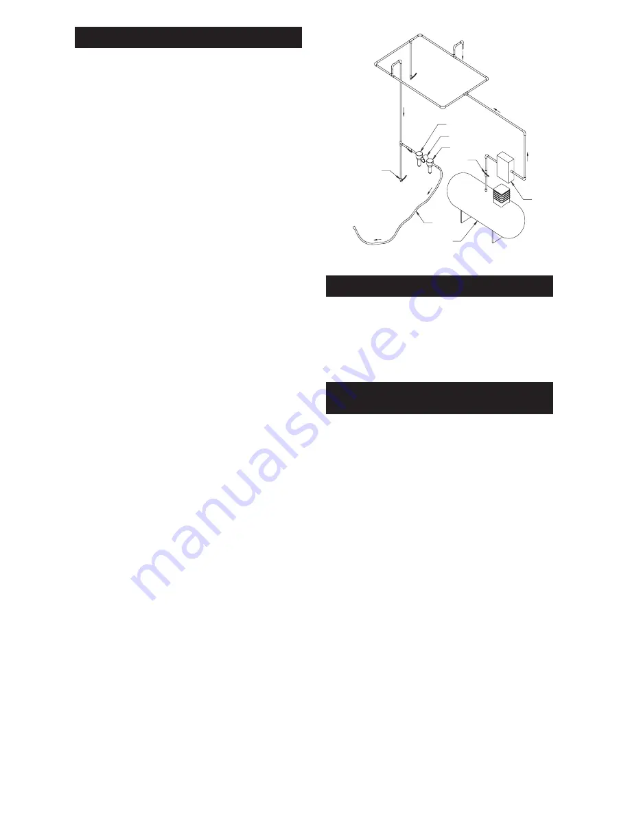
Figure 1
Closed Loop Pipe System
Sloped in the direction of air flow
Drain Leg
Ball Valve
To Tool Station
Filter
Drain Valve
Regulator
Lubricator
Ball
Valve
Ball Valve
Air Flow
Air Dryer
Air Compressor
and Tank
Air Hose
To Coupler
at or near Tool