background image

3D Systems, Inc.

44

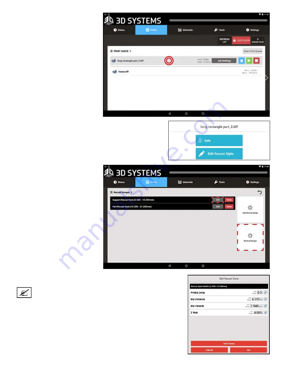
2.  To access the Recoat Parameter 

Modifications on-the-fly Wizard 

while the machine is idle, tap the 

file in the 

Print Queue

 screen.

a.  Tap the screen as shown 

at right. “Job Settings” 

does not contain the same 

options.

b.  Any job can be selected this 

way and the settings can be 

saved for later.

3.  When you select the build using either method, you will see the 

screen at the right. Select 

Edit Recoat Style

 to access the wizard. 

Selecting 

Info 

will show the BTE information for that build.

4.  The wizard will then open.
5.  From here, the user may open 

existing recoat styles and make 

adjustments. The user can also 

add recoat style ranges and 

sweeps to existing recoat styles.

6. 

All modifications can be reverted 

by selecting 

Restore Ranges

.

7.  When you tap the 

Edit

 button next to 

Support Recoat Style

, you will see the 

dialog window at the right.

NOTE: It is not recommended to add sweeps to this range .

Summary of Contents for ProX 800

Page 1: ...3D Systems Inc 1 User Guide Original Instructions Rev E P N 40 D044 ProX 800 3D Production Printer ...

Page 2: ...er Shut off 8 Emergency Stop 8 User Interface Laser LED 8 SAFETY LABELS AND INTERLOCKS 9 Laser Safety Warning Labels 9 Safety Interlock Switches 9 Voltage Compliance and ID labels 11 CHEMICAL SAFETY 14 Material Characteristics 14 Material Storage 14 Light 14 Temperature 14 Containers 14 Shelf Life 15 In Service Life 15 Contamination 15 Polymerization 15 Material Disposal 15 Material Spill Containm...

Page 3: ...SPRINT SOFTWARE OVERVIEW 47 SYSTEM OPERATIONS 48 Print Applicator Installation and Removal 48 Print Applicator Cleaning 49 Material Delivery Module MDM Installation 49 MDM Removal 51 Material Delivery Module Temperature Control 51 Auto Material Refill System 51 Installing Material Containers 52 Material Container Removal 53 Setting the Offload Position 54 Printing a Part 56 Home the Elevator 56 Se...

Page 4: ...ons Placard 72 Power Panel Layout Placard 73 Electrical Block Diagram Placard 74 Chamber Controller Placard 75 CUSTOMER SUPPORT 76 Customer Support Hotline 76 SERVICE 76 General 76 Laser 76 UV Radiation 76 LEGAL NOTICES 77 Copyright and Corporate Identity 77 FCC Notice 77 Radio Frequency Transmission 77 EC DECLARATION OF CONFORMITY 78 GLOSSARY 79 17 18 19 15 16 ...

Page 5: ... creating a print is covered in its entirety MAINTENANCE The section Maintenance on page 67 gives instructions for maintaining optimal functionality of your SLA system TROUBLESHOOTING AND CUSTOMER SERVICE In the section Troubleshooting on page 71 you can find a guide to fixing simple problems which may arise For further support refer to the sections Customer Support and Service on page 76 GLOSSARY...

Page 6: ...material has its own Material Guide Information specific to each material is included in the guides ProX 800 MATERIAL SAFETY DATA SHEETS AND SAFETY DATA SHEETS MSDS SDS Each material has its own MSDS SDS The user must be familiar with all information contained in these documents before handling the materials Every material shipment includes a paper copy of its MSDS SDS Electronic versions of each ...

Page 7: ...your ProX 800 Read and follow system instructions Follow all safety rules in this section and heed all cautions and warnings in this guide Do not attempt to open the chamber door or windows while a print is in process Do not use any material without first reviewing its Material Safety Data Sheet Safety Data Sheet MSDS SDS Secure the power and communication cables to prevent tripping Do not open pa...

Page 8: ...nterlocks are to be defeated only by trained personnel when needed during service procedures CONTROL SWITCHES The locations of control switches are illustrated in the section ProX 800 System Components on page 17 Master and Emergency power shut off switches are described in the following paragraphs 5 Emergency Stop All ProX 800 printers have Emergency Stop E Stop buttons on the right side panel an...

Page 9: ...r safety warning labels for the ProX 800 are located at system locations which are indicated above SAFETY INTERLOCK SWITCHES Safety interlock switches protect the user from possible UV Laser radiation exposure when certain doors or panels are opened Safety Interlocks are located behind the safety warning labels Behind door Laser safety labels on ProX 800 Laser safety label on cover of printhead On...

Page 10: ...D Systems Inc 10 Printhead DANGER Laser radiation when open WARNING Laser ON when lit Class IV 355nm 1 5Watt 120 microJoule Maximum UV Laser This device complies with 21 CFR chapter 1 subchapter J Laser ...

Page 11: ...3D Systems Inc 11 VOLTAGE COMPLIANCE AND ID LABELS Rear of ProX 800 Laser Label Maximum Wattage cTÜVus Label Product ID Label Voltage CE Mark Label ...

Page 12: ...stems Inc 12 MDM Product ID Voltage Label Model MDM ProX 800 Material Delivery Module for ProX 800 100 240VAC 50 60Hz 1PH 6A 3D Systems Corporation 333 Three D Systems Circle Rock Hill SC 29730 USA 286510 00 ...

Page 13: ...3D Systems Inc 13 ProX 800 ProX 800 Chamber controller panel AC Electronics Panel Main Power Disconnect Switch ProX 800 ...

Page 14: ...ines given in the MSDS SDS included with the print material and all applicable regulations local state and federal Protect print material from sunlight and ambient room light Print material may be stored in material carts with the lid securely fastened Material for the ProX 800 is composed of reactive monomers and oligomers If improperly stored or handled these compositions may undergo polymerizat...

Page 15: ...erization Signs of polymerization of stored material include container bulging leaking and the emission of heat or an unusual odor from the container If you notice this do not use the material and dispose of it properly Never mix different materials MATERIAL DISPOSAL Because stereolithography materials are regulated they are subject to special disposal requirements by your local federal or other r...

Page 16: ...to contact with liquid material Fume Inhalation Remove the person to fresh air Give artificial respiration or cardiopulmonary resuscitation CPR if required If breathing is difficult give oxygen Obtain immediate medical attention ENVIRONMENTAL CONDITIONS TEMPERATURE To allow optimum systems operation and optimum part quality the temperature of the ProX 800 System s room or other location should rem...

Page 17: ...cated on the side panel above the touch screen The E Stop immediately disables all motion controls and the laser rendering them safe After being pressed it remains in the closed state until it is manually returned to the open state by pulling the red knob and turning it clockwise An E Stop is also located inside the print chamber User Interface UI This is the control touchscreen which allows the u...

Page 18: ...Axis component of the A B C J I H A B C D E F G K L Both inner and outer electrical panels are removed printing process and can be manually controlled through the touchscreen Refer to the section Elevator Leveler Settings Screen on page 33 for instructions on manually operating the elevator through the touchscreen Omron Sensor This sensor indicates the material level in the MDM Print Applicator Th...

Page 19: ...Material Delivery Module MDM Installation on page 49 Chamber Lights There are two chamber lights inside the print chamber These can be turned on or off from the Chamber Lights button on the UI as well as the switch on the light itself For more information see the section User Interface on page 24 Safety Interlock Safety interlocks are used to ensure that doors and panels are not improperly opened ...

Page 20: ...mode the MDM is online and connected to the ProX 800 which provides the MDM s power and Input Output functionality The ProX 800 monitors and controls the material temperature while connected with the active MDM When the MDM is online it can pump and recirculate material The suitable material temperature for printing is 28 C 3 C Stand by Mode In this mode the MDM is offline and operates independent...

Page 21: ...onnector connects the Smart Cartridge Technology reader for the material container and establishes communication between the heater and the MDM see letter I below I O Connector This connector is the interface for all communication and motion control between the MDM and the printer Brake There are brakes on the two wheels at this end of the MDM They are labeled ON OFF to indicate which way to push ...

Page 22: ...ll Pump The peristaltic fill pump controls the material height in the MDM by moving material to or from the leveling reservoir see letter H For replacing the tubing on the peristaltic pump refer to the section Replace the Tubing in the Parastaltic Pump on page 68 Leveling Reservoir This reservoir is used to store material for transferring into or out of the print area to maintain the precise mater...

Page 23: ...clear the fault restart the machine Contact customer support if fault continues See the section Customer Support on page 76 Pulsing Active LED Turns green when the laser is energized The LED will switch between on and off during normal operation Ready LED Turns red when the laser has been activated and the laser control circuits are enabled Standby LED Turns green five minutes after the machine st...

Page 24: ...ated at the top of the print chamber NOTE The chamber lights can be repositioned to view specific areas as needed Check the switch on the lights themselves if they do not come on when you press the button under the user interface See the illustration below for the switch location LED Indicators The LED indicators indicate the readiness of the machine and its Lasers A B C USER INTERFACE The User In...

Page 25: ...can be offloaded with the manual offload cart to ensure optimal safety Refer to the section To Remove a Part on page 62 for information on operating the cart LIGHT STACK Red ON Solid E Stop is pressed ON Flashing Fault condition exists resulting in an aborted print job OFF Normal operating condition Amber ON Solid Printer is being serviced ON Flashing User warning or alert OFF E Stop is pressed Gr...

Page 26: ... and select Print3D Pro from the apps displayed 10 Print3D Pro Application Icon Press this icon to launch the Print3D Pro application Back Opens the previous screen you were working in even if it was in a different application app Home Navigates to the Home Screen If you are viewing an alternate Home screen this opens the central Home screen Recent Apps Opens a list of thumbnail images of apps you...

Page 27: ...e presented with a confirmation screen to verify your choice Current Settings This section displays various parameters of the current print job These are the values programmed using the 3D Manage software Refer to the application software help screens and manual for further information about these parameters Current Layer The end value of the layer currently being printed A B C D Material Temperat...

Page 28: ...chine will start printing However if it is not able to restart the printer will issue a print aborted notification which will be displayed as a pop up on the UI Refresh List Refresh the queue list on the UI If a user submits a job from a USB drive while in the queue menu the list will need to be refreshed Alternatively you can exit the queue and go back it will automatically refresh the list Unloc...

Page 29: ... is open Toggle back and forth between open and closed by selecting anywhere in the black bar for the month Print Job The specific print job is listed under the month Back Navigate back to the Print Queue screen described above Print Job Information Information about the job is listed here such as the duration of the print job material and date Information Press the information icon to bring up a ...

Page 30: ...ve to Top of Queue Move the current job to the top of the print queue Move Up Down in Queue Move the current job up or down in the print queue Move to Print History Select this button to move the print job to the Print History If currently in the print history selecting this will take you back to the Print Queue Delete Delete the job from the print queue Selecting this button after selecting the d...

Page 31: ...ion on the current material type expiration date of that material and batch number of the material in the MDM Leveling Reservoir Displays the weight of the material in the leveling reservoir Refill Bottle Displays the weight of the material in the refill container MDM Level Indicates the amount of material in the MDM The line indicates the nominal level of the material A B C D A D B C ...

Page 32: ...vator leveler manually See the section Elevator Leveler Settings Screen on page 33 for more detailed usage Print Applicator The Print Applicator Screen allows you to operate the applicator manually For more detailed usage see the section Print Applicator Screen on page 34 Printhead The Printhead Screen gives the user access to functionality of the Printhead See the section Printhead Settings Scree...

Page 33: ...it Set Start Saves the elevator s current position as the Start position See Printing a Part on page 56 for instructions on setting the Set Start position Set Offload Saves the elevator s current position A as the Print Offload position The offload position comes pre set in the software however some adjustments may need to be made If the Move to Offload button needs to be adjusted follow the steps...

Page 34: ...f sync Allow Motion Motion Not Allowed This message pops up when you open the screen It indicates whether or not the system is in a A state where the print applicator can be operated manually To operate the print applicator the elevator must be at least 2 inches below the surface of the print material and the applicator must not be able to collide with the elevator This can usually be accomplished...

Page 35: ... pinhole to ensure that the laser is drawing in the proper spot This works as a checkpoint to ensure that printing is starting at the same point Up Down Left Right Arrows Manual motion control for the IPM Beam Hold the arrow down to move Set as Rest Set the current IPM Beam position as the rest position Move to Rest Move the IPM Beam to the stored rest position Check Laser Checks the IPM power and...

Page 36: ...n on page 38 Network Settings Navigate to the Network Settings screen See the section Network Settings Screen on page 38 Heater Settings Navigate to the Heater Settings screen See the section Heater Settings Screen on page 39 Default Scale Factor Navigate to the Default Scale Factor Settings screen See the section Scale Factor Settings Screen on page 40 Build Settings Navigate to the Build Setting...

Page 37: ...ttings tab will appear after you launch the Print3D Pro application Press the ADD MANUALLY button You will be prompted to enter the IP address for your printer The address will vary depending on your setup If you do not know your address contact your systems administrator Enter the correct address into the field and press ADD Your printer will appear in the list Press the name of the printer to co...

Page 38: ...GS SCREEN The Network Settings Screen allows the user to view the values related to the system network IP Address View the IP address for the system MAC Address View the MAC Address for the system Hostname View the network host name of the system DNS Address View the main TCP IP address for the DNS Server Default Gateway Address View the TCP IP address for the Default Gateway DHCP Switch the Dynam...

Page 39: ...eater MDM Heater View the current temperature for the MDM heater Print Chamber Heater Edit the temperature for the print chamber heater MDM Heater Edit the temperature for the MDM heater For any field that you need to set press the key to edit Set Print Chamber Temperature Saves the settings for the Print Chamber Temperature Set MDM Temperature Saves the settings for the MDM Temperature A B C A B ...

Page 40: ... too small they will enter scale factors to adjust for the errors and repeat the process until the error is zero or small enough to not affect the quality of the part X Value View the current x axis scale factor Y Value View the current y axis scale factor Z Value View the current z axis scale factor X Value Edit the current x axis scale factor Y Value Edit the current y axis scale factor Z Value ...

Page 41: ...e Auto Drain and Smart Sweep on or off Auto Drain automatically lifts the print pad from the MDM after the print is finished so that the excess material drains off of the part Smart Sweep confines the sweeper motion to only the area of the parts being printed This is the default mode ProX 800 ...

Page 42: ...UI v1 1 5443 this feature provides the user more control over the process of restarting a build that has been interrupted 1 Select Restart Last Job from the status screen NEW FUNCTIONALITY FOR GUI V1 1 5443 Current Position Displays the current X Position Current Position Displays the current Y Position X Value This is where the current X Value can be edited Select the key to edit This will shift ...

Page 43: ... choose whether or not to home the elevator adjust elevator position sweep the applicator level the material add additional wait time to the current layer select a specific layer or rescan the selected layer multiple times b If the elevator has not been homed the user may move the elevator downward but not upward c If the applicator has not been homed the user cannot move the elevator up beyond th...

Page 44: ...hod you will see the screen at the right Select Edit Recoat Style to access the wizard Selecting Info will show the BTE information for that build 4 The wizard will then open 5 From here the user may open existing recoat styles and make adjustments The user can also add recoat style ranges and sweeps to existing recoat styles 6 All modifications can be reverted by selecting Restore Ranges 7 When y...

Page 45: ...sweeps can be added 9 Back on the wizard home screen when you tap the Add Recoat Range button you will see the dialog window at the right Adding ranges is very similar to adding ranges in 3D Manage The user selects start and end Z ranges 10 Ranges added between existing ranges will automatically create additional ranges to fill in the full Z range a Example Add range 12mm 20mm to a build with Z ra...

Page 46: ...l in the MDM 1 This tool can be accessed from the Elevator Leveler Settings screen by tapping Stir 2 Once the Stir wizard is opened the user is granted more control over how the machine Stirs the material 3 While the machine is stirring the user will be shown a countdown to when the stir will end seen at right NOTE The new rendering style is not active by default It must be activated via the App S...

Page 47: ... detailed information on the features of 3D SPRINT as well as user guides for part preparation you can access the full help document by clicking on the icon inside the 3D SPRINT software NOTE If you do not have 3D SPRINT loaded on your computer you can obtain a copy at http infocenter 3dsystems com product library prox 800 software downloads NOTE Although there are QC styles in 3D SPRINT it will n...

Page 48: ...lures In this case the applicator tabs will need to be replaced If the applicator itself is damaged it will need to be replaced 12 Locating Pins Locating Holes Thumb Screws Applicator Tabs Print Applicator Rear View Print Applicator Front View Applicator pins fit into locating holes Lightly fasten using the thumb screws Remove Applicator from MDM 2 1 3 To install the applicator do the following 1 ...

Page 49: ...es NOTE Move the MDM very slowly Sudden starts and stops can create waves in the material and result in material spills even with the MDM lid in place Continuous slow movement is critical to preventing any movement of the printer with the heavy MDM Any change in the printer s inner frame placement will require recalibration by a trained service technician 1 Open the front door of the ProX 800 Make...

Page 50: ...king pin and MDM bracket 5 Once the MDM is in the machine connect the cables on the front of the MDM as shown 6 Plug the I O Connector into the first input The I O connector is the large circular plug with the bundled gray wires 7 Plug the Serial Connector into the second input Secure the connection by turning the collar on the connector clockwise 8 There is a black three pronged power cord that p...

Page 51: ...f the machine follow these steps 1 From the Elevator Leveler Settings Screen press the Drain MDM button to transfer material to the leveling reservoir which will reduce the risk of overflow when rolling the MDM out of the printer 2 Move the elevator to its lowest position so the forks can remain with the MDM The elevator will stop when it reaches this position From the Print Applicator Screen pres...

Page 52: ...talled in the MDM 3 Verify the material bin is clean of any material and is completely dry if alcohol has been used to clean it 4 Pull the material bin s release lever away from the MDM to a 45 angle from the vertical position 5 Insert the material container into the slot 6 Look at the status on the user interface If the status is okay push the container until you hear a click Try to lift up on th...

Page 53: ... disposable nitrile gloves and goggles while performing the following steps 1 Retrieve the original vent cap for the current material container and fasten it tightly on the vent hole to prevent the material from leaking out when removed 2 Pull down on the MDM release lever until it is at a 45 angle from the vertical position 3 Push the container release button 4 Lift the material container out of ...

Page 54: ...ve ex 5 will move print pad up This is a good place to start 2 Press Set 3 Repeat these steps until the print pad is far enough up to get the Manual Offload Cart under it without damaging the recoater or to reach the timing plate Refer to the section To Remove a Part on page 62 NOTE If the print pad is too high you can reverse it by typing 5 minus sign Set in the editing keypad to set a negative v...

Page 55: ...t under it without damaging the recoater or to reach the timing plate Refer to the sections Remove a Part Without Offload Cart on page 62 and Print Pad Removal on page 50 NOTE If the print pad is too high you can reverse it by typing 5 minus sign Set in the editing keypad to set a negative value This moves the print pad down 5 Select Set Offload 1 NOTE This position will now be saved and can be us...

Page 56: ... 5 5 Home the Elevator If the printer was not already turned on 1 Select Tools from the main screen 6 2 Select Elevator Leveler 7 3 Select Move to Home 8 2 3 4 1 ProX 800 8 1 If necessary turn the machine on by ensuring that the printer is plugged in then turning the power disconnect switch to the ON position For the location of the switch see the section ProX 800 Printer Inside View on page 18 2 ...

Page 57: ...ed it is advised that Move to Start 9 be selected and the MDM leveled by pressing the Level MDM button to make sure that all settings have been retained for optimal printing If not you will need to repeat the preceding steps to reset your Start Position NOTE After setting the Start Position there may be bubbles in the MDM Bubbles must be removed before printing To remove bubbles follow the instruc...

Page 58: ...p on the screen Select the file you wish to print and press the Submit button The file selected should be loaded in the Print Queue ProX 800 4 If the file is not in the top position tap the file to highlight it then tap the Jump to Top button to move the file to the top of the queue 3 3 Removing Bubbles If bubbles appear in the material they must be removed prior to starting a print Follow these s...

Page 59: ... is necessary to let excess resin drain off the part s To drain the resin do the following 1 If your part has not auto drained after finishing you must go to Tools Elevator Leveler Settings Move to drain 2 Once the build platform is moved to drain level leave it flat Figure 1 to drain the part s for about 30 minutes 3 After 30 minutes you may use the arm located under the build platform to tilt it...

Page 60: ...menu 2 Place the print pad between the L shaped guides 1 towards the rear of the print chamber 3 Pull the print pad forward against the print pad notched guides at the front 2 4 Make sure that the front edge of the print pad engages with the notched print pad guides 5 Move the elevator to the Start position by pressing Move to Start on the Elevator Leveler screen under the Tools menu Elevator Plat...

Page 61: ...its offload position If necessary move it to its offload position by selecting the Move to Offload button on the Elevator Leveler screen under the Tools menu 2 Lower the print platform onto the elevator forks by pulling lever on the offload cart down 3 Perform steps 2 5 on the previous page NOTE If this is right after a build you may get the warning message Print applicator is not at home position...

Page 62: ...d water NOTE Do not clean build platform while over the vat as debris from paper towels or cleaning agents will contaminate the resin below 2 You may see a popup asking Is platform in lowered position Click yes 3 Being in this position near the timing plate the latches for the print pad will be disengaged 4 Allow part s to drain over vat for 30 minutes 5 Wearing nitrile gloves remove the print pla...

Page 63: ...hine To remove build parts from the platform follow the steps outlined in the section Post Processing of Build Parts 1 Remove Print Platform With Offload Cart 1 The default offload position for the system with a cart should be set higher than one without a cart Allow part s to drain over vat for 30 minutes Ensure there is enough room to slide the offload cart under the print pad without touching t...

Page 64: ... THE PROPER METHODS OF DISPOSAL OF 3D PRINT WASTE MATERIAL NOTE Do not simply remove the parts from the build platform without first removing the build platform from the machine and performing all these steps Removing parts while they are still in the machine could cause build debris to end up in the MDM and cause damage to future builds 1 Wearing nitrile gloves move the build platform onto the RA...

Page 65: ...d below right to start the IPA bath 4 After IPA bath is finished hold build platform at an angle above the IPA vat to drain excess IPA 5 Set build platform on offload cart or other large sturdy cart to prepare for part removal 6 With nitrile gloves on use a putty knife or other viable tool to scrape the build s supports off the build platform 7 Carefully remove other support structures by hand Dra...

Page 66: ...to smooth out the bottom of the part s as needed Procedure is now complete NOTE From time to time you will need to switch out your TPM and IPA for fresh liquids The type of material you typically build with will dictate how often to do this as all materials have different solubilities Some materials will exhaust the solvents effectiveness much faster than others For either solvent closely monitor ...

Page 67: ...tative PREVENTIVE MAINTENANCE Your ProX 800 must have preventive maintenance performed by a qualified 3D Systems Customer Support Representative Contact 3D Systems to schedule this There is a charcoal filter at the top of the back side of the machine that will be replaced every six months during the preventive maintenance performed by a qualified 3D Systems Customer Support Representative CUSTOMER...

Page 68: ...g i e a Tupperware container Procedure 1 Note the routing of the hose on the MDM You will need to reinstall it as it exists on your MDM The routing of your hose may differ from some of the pictures below 2 Tighten the reservoir connection valve 1 by turning it clockwise to stop the flow of print material 3 Loosen the two hose clamps from the valves using a flathead screwdriver 2 Peristaltic Pump P...

Page 69: ...anism to remove hose Open cover to access inside Place hose over drip container to catch any excess print material Have paper towels available to wipe up excess print material 5 Using a pair of wire cutters cut all zip ties which are securing the hose to the MDM 6 Unfasten the peristaltic pump cover using a flathead screwdriver 5 Open the panel to gain access to the internal mechanism 6 5 6 7 8 7 ...

Page 70: ...f hose from connector and hold vertically Let print material drain from hose into the drip container 9 10 9 Dispose of the hose and excess print material according to any applicable regulations 10 Replace with the new hose connecting it as the original hose was Slide hose clamps onto each end of the hose Connect the top part of the hose to the connector and fasten the hose clamp Insert the hose in...

Page 71: ...e 74 for connector locations Entire system does not power up An E Stop is depressed Reset the E Stop s and press system enable Main power plug is not engaged Plug cord into the wall outlet No power is coming from the wall Reset circuit breaker for the wall outlet The circuit breaker is tripped Reset circuit breaker in the back of the machine Printhead IPM does not operate The laser is not turned o...

Page 72: ...3D Systems Inc 72 LASER CCB ELEVATOR MDB AIR HEATER MDM LSR INTLK CCB MDB P1 P4 USER INTFC J2 J5 DOOR SW POWER PANEL CONNECTIONS PLACARD ...

Page 73: ...PST 24V COIL 1W ESTOP CIRCUIT CR2 RELAY 3A SPST 24V COIL 1W DOOR SW CIRCUIT CR3 RELAY 6A SPST 24V COIL 1 5W DOOR SW CIRCUIT TB1 1 TERMINAL BLOCK ST6 52A 46A LINE TB1 2 TERMINAL BLOCK ST6 52A 46A LINE GND GND TERMINAL BLOCK ST6 N A GND TB2 1 TERMINAL BLOCK PIT2 5 QUAT N A 24VDC TB2 2 TERMINAL BLOCK PIT2 5 QUAT N A 24R TB2 3 TERMINAL BLOCK PIT2 5 QUAT N A ESTOP TB2 4 TERMINAL BLOCK PIT2 5 QUAT N A 2...

Page 74: ...3D Systems Inc 74 ELECTRICAL BLOCK DIAGRAM PLACARD ...

Page 75: ...OTOR DRIVES INTERLOCK CAT 6 CBLS CHAMBER CONTROLLER DUAL ENCODER ENCODER CABLE CARRIER MOTOR LIMS TO COMPUTER DSP 24V BRAKE POWER ENABLE 24V 12V VACUUM SENSOR Z AXIS X AXIS PROX SENSOR RECOAT Y AXIS LASER SENSOR Z AXIS PCB RECOAT PCB ENC LIMS STEP MOTOR STEP MOTOR LIMS REC BAR RESIN HT VAC SENSORS RECOAT PCB 6PR SHLD 14PR SHLD CH LIGHT VAC PUMP SKYEREAD TO PC COM 7 LIGHT TOWER CRTL K22 CB21 RESIN ...

Page 76: ...ur system needs service contact 3D Systems Technical Support at the following numbers In the United States or Canada call 800 793 3669 In Europe call 49 6151 357357 You can also contact your local 3D Systems representative 3D Systems support portal is located at http www 3dsystems com support For Material Safety Data Sheets Safety Data Sheets MSDS SDS go to http www 3dsystems com support materials...

Page 77: ...ntial area is likely to cause harmful interference in which case the user will be required to correct the interference at his own expense Changes or modifications not expressly approved by 3D Systems could void your authority to operate equipment RADIO FREQUENCY TRANSMISSION This product generates 13 56 MHz using an Inductive Loop System as a Radio Frequency Identification device RFID This RFID de...

Page 78: ...3D Systems Inc 78 ...

Page 79: ... depth The thickness or depth of cured material The cure depth of any line is determined by the laser beam power and distribution Laser draw speed and material characteristics Curl A characteristic type of part deformation Draining Enabling material to drip from the finished part into the MDM when the elevator is at its top position to minimize material waste Drawing speed The speed at which the L...

Page 80: ... SDS Material Safety Data Sheet Safety Data Sheet Federal government mandated information about the chemical makeup of any chemical substance such as photocurable resin Usually includes identification of toxic substances and safe handling guidelines NIOSH National Institute for Occupational Safety and Health Photoinitiator A chemical in photopolymers that reacts with photons and catalyzes the poly...

Page 81: ... that blocks the laser beam when an interlock switch is activated or when closed via the user interface Scan speed See Draw speed Sensitization An allergic response to a chemical stimulus such as photocurable resin generally resulting from repeated skin contact Skin skin fill See Fill vectors SLA Center See Stereolithography apparatus Stereolithography apparatus The equipment used to produce stere...

Page 82: ...let UV Electromagnetic radiation having a wavelength shorter than visible light i e below 390 nanometers Vat On older SLA Centers the metal container inside the process chamber that holds the material from which the object is formed On the ProX 800 this container is called the MDM Vector A directed line segment represented by starting and ending coordinates as defined in a stereolithography slice ...

Page 83: ...3D Systems Inc 83 3D Systems Inc 333 Three D Systems Circle Rock Hill SC 29730 www 3dsystems com 2017 3D Systems Inc All rights reserved p n 40 D044 Rev E ...

Reviews: