3D Robotics Aero Instruction Manual Download Page 3

3

Safety

!

Before you fly, always determine the boundaries of your safe flying area. If 

the Aero moves outside the designated area or exhibits instability in flight, 

switch to fly-by-wire mode and land the plane manually.

The Aero will not avoid obstacles on its own, including during missions. As 

the operator, it’s your job to recognize and avoid obstructions while flying. 

Always be ready to regain manual control of the plane in the event of an 

unsafe situation. 

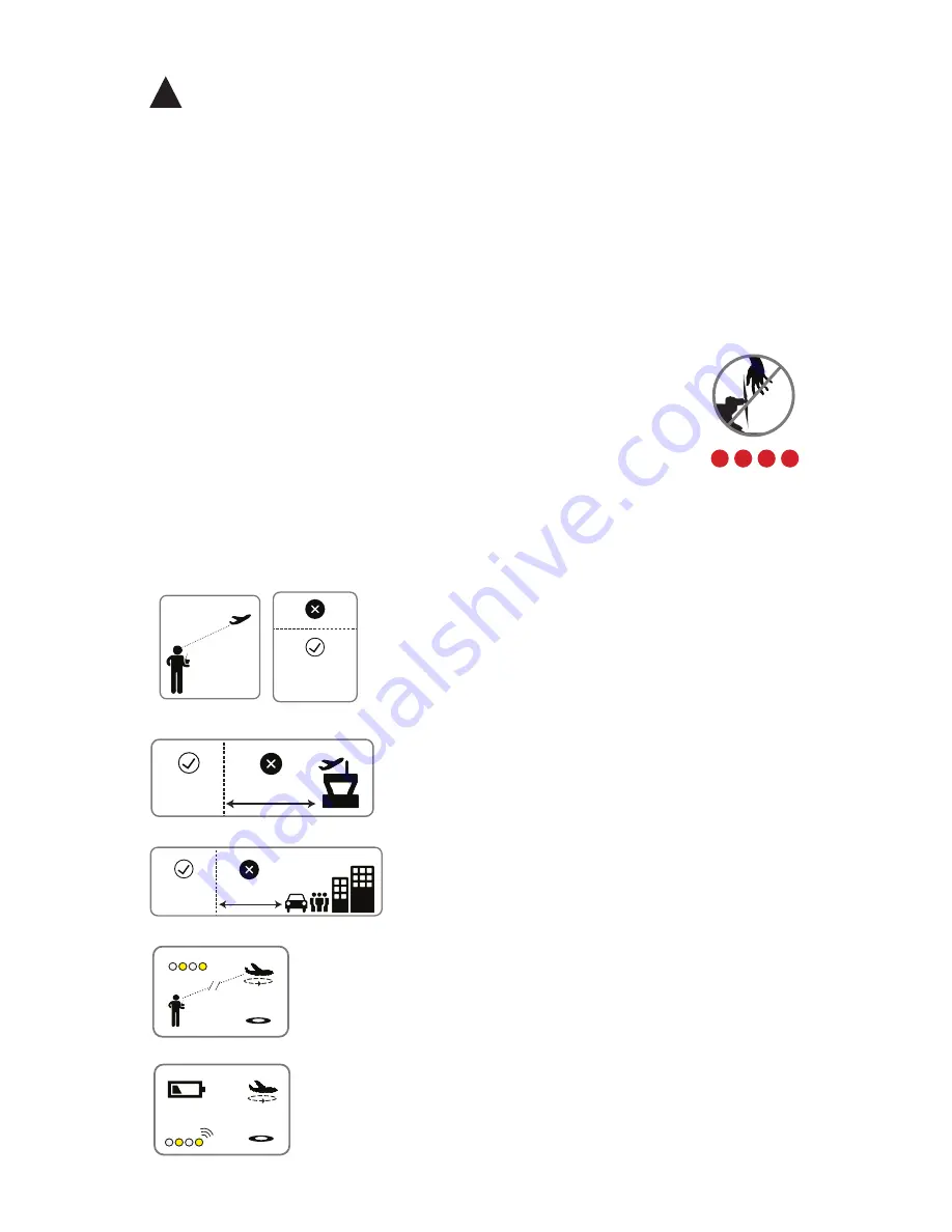
Spinning propellers can cause serious injury. The safety button 

indicates the status of the motor to help you prevent hazardous 

contact with the Aero’s high-speed propeller. When the Aero is 

powered on, the safety button will blink red; the motor is inactive 

and the propeller is safe to handle. When you’re ready to fly, press 

and hold the safety button until it shows solid red. This indicates 

that the motor is active and the propeller can spin if armed. To 

make the propeller safe to handle again, press and hold the safety 

button until it blinks red.

visual line 

of sight

400 ft

(120 m)

100 ft (30 m)

5 miles (8 km)

visual line 

of sight

400 ft

(120 m)

100 ft (30 m)

5 miles (8 km)

Always fly at least 100 feet (30 m) away from 

people, vehicles, and buildings. Make the safety 

of people and property your first priority!

Always fly below 400 ft (120 m) and within your 

visual line of sight. Don’t let the Aero get too far 

away from you; make sure you can always see its 

orientation. Don’t fly in low light, heavy wind, rain, 

or other conditions that might impede visibility.

Always fly at least five miles (8 km) away from 

airports and other areas where pilots operate 

manned aircraft.

visual line 

of sight

400 ft

(120 m)

100 ft (30 m)

5 miles (8 km)

visual line 

of sight

400 ft

(120 m)

100 ft (30 m)

5 miles (8 km)

visual line 

of sight

400 ft

(120 m)

100 ft (30 m)

5 miles (8 km)

If the Aero looses contact with the RC transmitter, it will 

return to the launch point automatically and enter into a 

circle pattern above the launch point, indicated by a 

blinking yellow status LED.

visual line 

of sight

400 ft

(120 m)

100 ft (30 m)

5 miles (8 km)

visual line 

of sight

400 ft

(120 m)

100 ft (30 m)

5 miles (8 km)

If the battery reaches 33% of its remaining charge, the 

Aero will return automatically to circle above the launch 

point, indicated by a blinking yellow status LED and a 

quick repeating tone.

Summary of Contents for Aero

Page 1: ...l to get started with your new autonomous aircraft 1 Meet the Aero 7 Fly by wire mode 2 Safety 8 Command modes 3 Charge battery 9 Missions 4 Setup 10 Preflight steps 5 Manual mode 11 Takeoff landing 6 Stabilize mode 12 Postflight steps body tail boom tail left wing motor Meet the Aero nose right wing ...

Page 2: ...transmitter Spektrum FlySky battery compartment airspeed sensor electronics compartment under wings rudder elevator left aileron right aileron If the terms above are unfamiliar to you visit 3dr com learn and dive into the exciting world of planes with our Introduction to Flying Fixed Wing Aircraft ...

Page 3: ...e safety button until it blinks red visual line of sight 400 ft 120 m 100 ft 30 m 5 miles 8 km visual line of sight 400 ft 120 m 100 ft 30 m 5 miles 8 km Always fly at least 100 feet 30 m away from people vehicles and buildings Make the safety of people and property your first priority Always fly below 400 ft 120 m and within your visual line of sight Don t let the Aero get too far away from you m...

Page 4: ...cable to the port Set the charger to LiPo and 3A The Aero is powered by a rechargeable lithium polymer LiPo battery Store the battery at half charge then charge fully before flying Batteries must ship at half charge so please charge before your first flight Each full battery provides approximately 40 minutes of flight time battery charger ...

Page 5: ...ag Charge the battery using a designated LiPo balance charger only Always monitor the battery while charging Flying with a low battery is a safety risk and can render the battery permanently unusable Always fly with a fully charged battery Inspect the battery for damage before takeoff and after landing If you observe any swelling of the package or the battery ceases to function locate your local b...

Page 6: ...nge groove Make sure not to stress any of the components on the tail Follow these instructions to take the Aero from travel configuration to flight configuration 1 On the top of the horizontal stabilizer open the blue clasp at the end of the servo rod Setup vertical stabilizer complete tail assembly ...

Page 7: ...e Locate the wing spar long rod and the two wings Slide a wing onto the spar 2 Turn the plane over and insert the provided tail screw into the horizontal and vertical stabilizers Insert the pegs on the clasp into the open space in the servo horn and close the clasp servo horn ...

Page 8: ...the two cables on the wings marked AILE Either of the wing cables can connect to either of the plane cables the order doesn t matter plane AILE cables wing AILE cables Place the wings over the body of the Aero with the foam squares fitted into the matching space in the electronics compartment Make sure not to pinch the AILE cables wings placed onto the body of the Aero complete wing assembly ...

Page 9: ...right triangles complete band assembly Locate the four large rubber bands Use the bands to secure the wings to the body of the Aero by the four orange knobs on the body around the wings Attach two of the bands to the two knobs on one of the short sides and opposite knobs on the opposing side orange knobs add first band add second band ...

Page 10: ...nd largest internal diameter and insert it into the back of the propeller hub 3 Remove the nut and the washer from the motor add the propeller with the writing on the propeller facing towards the nose of the plane add the washer and the nut over the propeller and tighten the nut ...

Page 11: ... these steps The tail boom arrives attached to the Aero Follow these instructions to remove the tail boom for travel Disconnect the RUDD and ELEV cables inside the electronics compartment body tail Remove the screws on the body and the tail indicated below ...

Page 12: ...d GEAR MIX three position switch marked FLAP GYRO available positions 0 1 2 Setting flight modes On 3DR transmitters use the two position switch and the three position switch shown below to select a flight mode FlySky mode switches two position switch marked AIL D R available positions 0 1 three position switch marked F MODE available positions N 1 2 The two position switch activates one of the tw...

Page 13: ...o N for RETURN TO LAUNCH 1 for FLY BY WIRE 2 for AUTONOMOUS With AIL D R set to 1 set F MODE to N for LOITER 1 for STABILIZE 2 for MANUAL The Aero includes six flight modes Manual mode two assisted flight modes stabilize and fly by wire autonomous mission mode and two command modes loiter and return to launch The following sections of this manual describe the behavior of each mode The Aero s six m...

Page 14: ...ives you the most direct input to the control surfaces resulting in precise in flight adjustment Try manual mode if you re an experienced RC plane operator Manual mode RC controls Left Stick Left Stick Left Stick Left Stick Throttle up Increase motor speed Throttle down Decrease motor speed Left Stick Left Stick Throttle fully down Stop motor ...

Page 15: ...i c k Yaw left Left Stick L e f t S t i c k L e f t S t i c k Left Stick Pitch up L e f t S t i c k L e f t S t i c k L e f t S t i c k Left Stick Roll left Pitch down Yaw right Turn left Turn right Pitch up Pitch down Roll right Roll left Roll right ...

Page 16: ...ill automatically return to a level flying orientation Use stabilize mode for the freedom of manual control with return to level stabilization Stabilize mode RC controls roll pitch yaw throttle Left Stick Left Stick Left Stick Left Stick Throttle up Increase motor speed Throttle down Decrease motor speed Left Stick Left Stick Throttle fully down Stop motor ...

Page 17: ... Stick Left Stick L e f t S t i c k Yaw left Left Stick L e f t S t i c k L e f t S t i c k Left Stick Pitch up L e f t S t i c k L e f t S t i c k L e f t S t i c k Left Stick Roll left Pitch down Yaw right Turn left Turn right Pitch up Pitch down Roll right Roll left Roll right ...

Page 18: ...u want the Aero to fly Fly by wire mode FBW is the easiest way to fly and is the recommended mode for new fliers FBW mode RC controls stabilized roll stabilized pitch yaw throttle Left Stick Left Stick Left Stick Left Stick Throttle up Increase motor speed Throttle down Decrease motor speed Left Stick Left Stick Throttle fully down Stop motor ...

Page 19: ... Left Stick L e f t S t i c k Yaw left Left Stick L e f t S t i c k L e f t S t i c k Left Stick Pitch up L e f t S t i c k L e f t S t i c k L e f t S t i c k Left Stick Roll left Pitch down Yaw right Turn left Turn right Pitch up Pitch down Roll right Fly to the left Fly to the right ...

Page 20: ...k prior to takeoff GPS lock required Loiter mode GPS positioned circling The Aero will enter into a circle pattern with a radius of 60 meters at the current altitude Move the right stick to adjust the position of the circle Return to launch mode circling over launch point The Aero will return to the position where it acquired GPS lock and enter into a circle pattern at an altitude of 100 meters GP...

Page 21: ...itch into autonomous mode to start the mission Use a ground station computer with the provided Telemetry Radio to fly a fully autonomous mission To download software and learn how to plan a mission visit 3dr com learn laptop ground station with 3DR Telemetry Radio Do not set the Aero to autonomous mode without following the mission planning instructions at 3dr com learn To fly a mission with autom...

Page 22: ...fety button until solid red 5 Check LED for blinking blue no GPS or blinking green GPS locked GPS GPS X Check manual controls 3 Throttle Pitch up and down Roll left and right Yaw left and right 4 Check autopilot stabilization Pitch up and down Roll left and right Wings and tail attached Tail boom secure Servos and rods secure Airspeed sensor secure Propeller tight Transmitter on 1 Go outside to an...

Page 23: ... to secure the components to the foam Power on the RC transmitter and set the throttle fully down airspeed sensor Check that the airspeed sensor is secured to the side of the Aero and the tube is free from obstructions Open the battery compartment by sliding the knob on the orange switch and lifting out the foam lid 2 ...

Page 24: ...ile it powers on Secure with the velcro strap Close lid by aligning the orange notches at the nose With the battery connected and the lid secured check that the Aero is correctly balanced for flight Hold the Aero with one finger on each of the clear plastic balancing points shown below These points indicate the Aero s center of gravity 3 ...

Page 25: ...y by wire modes you may proceed when you see the blinking blue light 4 LED Autopilot ready no GPS Autopilot ready GPS locked If the plane balances on your fingers then the center of gravity is correct If it won t balance adjust the position of the battery until you can balance the plane on two fingers as shown below Initializing please wait To arm the motor press and hold the safety button until i...

Page 26: ...se the throttle slightly until the motor spins then immediately set the throttle back to fully down position Motor spins Left Stick L e f t S t i c k Pitch down Elevator tilts down L e f t S t i c k Left Stick Pitch up Elevator tilts up Do not raise the throttle more than just enough to spin the motor while the plane is on the ground and do not place your hands in the way of the propeller while th...

Page 27: ...ft aileron tilts up right aileron tilts down L e f t S t i c k L e f t S t i c k Roll right Left aileron tilts down right aileron tilts up Left Stick Left Stick Yaw left Rudder tilts left Left Stick L e f t S t i c k Yaw right Rudder tilts right ...

Page 28: ...the stabilization response from the control surfaces 7 Test Tilt the plane left Result Left aileron tilts down right aileron tilts up Test Tilt the plane right Result Left aileron tilts up right aileron tilts down Test Tilt the plane down Result Elevator tilts up Test Tilt the plane up Result Elevator tilts down ...

Page 29: ...of you Face into the wind and hold the Aero at the center of gravity Raise the throttle to center position to start the motor Be careful not to place your hand in the way of the propeller Left Stick Once launched the Aero will require immediate adjustment with the transmitter to navigate away from the ground and up to the desired altitude Pitch up right stick down and add any other necessary contr...

Page 30: ... the throttle fully down to turn off the motor and glide down on a 15 to 20 degree down pitch angle When the plane is one meter above the ground pitch up flare to land the Aero on the body of the plane instead of the nose throttle fully down pitch up 20 40 m 10 m 1 m wind direction Left Stick Left Stick pitch slightly down After stopping the motor at an altitude of 10 m keep your thumb on the thro...

Page 31: ...fety button until it displays blinking red 1 safety button Inactive motor disarmed Active motor armed Disconnect battery 2 Turn off transmitter 3 Your flight is now complete Always following the preflight and postflight steps described in this manual when you fly ...

Page 32: ...ying configuring and using a ground station with the Aero Support For customer support contact us at help 3dr com or call our support line at 1 858 225 1414 Monday through Friday from 8 am to 5 pm PST FPV OSD video If you received an FPV OSD video system with your Aero visit 3dr com learn for instructions on operating your video system Happy flying Aero User Manual A 3D Robotics Inc 12 August 2014...

Reviews: