4-26
C
HAPTER
4: M
ANAGING
THE
S
WITCH
3000 10/100
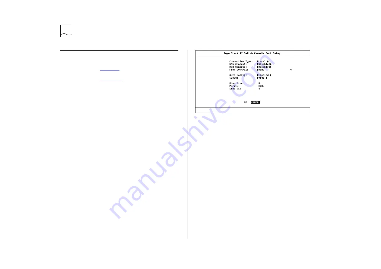
Setting Up the Console Port
From the Switch Management Setup screen,
described in
, select the CONSOLE PORT
button. The Console Port Setup screen is displayed
as shown in
If you change any of the console port parameters,
you terminate any existing sessions using the con-
sole port when you exit the screen. Ensure that the
connected equipment’s console port parameters are
set to match the new configuration. This allows
you to continue to access the management facility
from the equipment after you change the console
port parameters.
The screen shows the following:
Connection Type
Local / Remote
This field allows
you to select the type of console port connection.
Select
Remote
if you want to manage the Switch via
a modem; DCD Control and DSR Control are
enabled. For all other cases, this field should be set
to
Local
.
DCD Control
Enabled / Disabled
This field is only
applicable to local connection types. It determines if
DCD is required for a local connection, and
whether the connection is closed if DCD is removed.
Refer to your terminal or modem user documenta-
tion if you are unsure of the correct setting.
Figure 4-17
Console Port Setup screen
DSR Control
Enabled / Disabled
This field is only
applicable to local connection types. It determines if
DSR is required for a local connection, and whether
the connection is closed if DSR is removed. Refer to
your terminal or modem user documentation if you
are unsure of the correct setting.
Flow Control
XON/XOFF / NONE /
RTS-CTS Unidirectional / RTS-CTS Bidirectional
This
field allows you to select the correct flow control
option for your terminal or modem. Refer to your
terminal or modem user documentation if you are
unsure of the correct setting.
Auto Config
Enabled / Disabled
The Switch can
auto-configure the line speed (baud rate) to work
with your VT100 terminal. This field allows you to
specify whether auto-configuration is enabled.
Summary of Contents for SuperStack II Switch 3000 10/100
Page 14: ...1 6 CHAPTER 1 GETTING STARTED Figure 1 2 Increasing port density with the Switch 3000 10 100 ...
Page 15: ...Unit Overview Front 1 7 Unit Overview Front Figure 1 3 Switch 3000 10 100 front view ...
Page 17: ...Unit Overview Rear 1 9 Unit Overview Rear Figure 1 4 Switch 3000 10 100 rear view ...
Page 22: ...1 14 CHAPTER 1 GETTING STARTED ...
Page 25: ...Configuration Rules with Full Duplex 2 3 Figure 2 1 Fast Ethernet configuration rules ...
Page 112: ...6 12 CHAPTER 6 STATUS MONITORING AND STATISTICS ...
Page 128: ...C 6 APPENDIX C TROUBLE SHOOTING ...
Page 129: ...D PIN OUTS Null Modem Cable 9 pin to RS 232 25 pin PC AT Serial Cable 9 pin to 9 pin ...
Page 130: ...D 2 APPENDIX D PIN OUTS Modem Cable 9 pin to RS 232 25 pin RJ45 Pin Assignments ...
Page 142: ...6 GLOSSARY ...


