Setting Up Resilient Links
4-19
Configuring Resilient Links
With the Switch Management screen displayed,
choose the port to be the main port in the resilient
link pair, then select the RESILIENCE button.
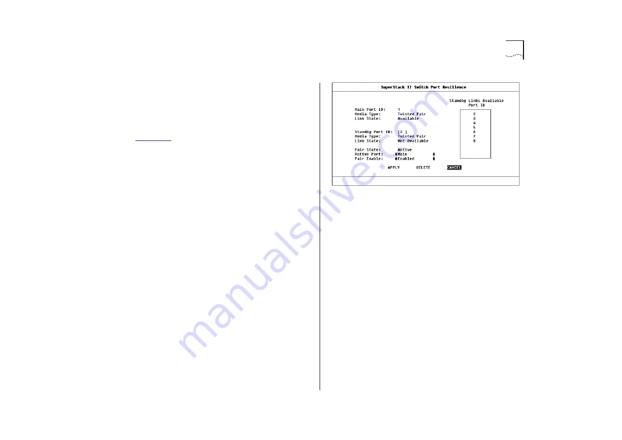
The Port Resilience screen is displayed, as shown in
. This screen allows you to set up, edit
and delete resilient link pairs.
The screen shows the following:
Main Port ID
This read-only field shows the ID of
the main port.
Media Type
Twisted Pair / Fiber
This read-only field
indicates the media type connected to the main
port.
Link State
Available / Not Available / Not Present
This read-only field shows the connection state of
the main port:
■
Available
— The port is operating normally
■
Not Available
— The resilient link pair is disabled
■
Not Present
— The port is not present in the cur-
rent hardware
Standby Port ID
This field shows the current
standby port ID and allows you to enter a new port
ID. The standby port must be in the same VLAN as
the main port.
Media Type
Twisted Pair / Fiber
This read-only field
indicates the standby port media type.
Figure 4-14
Switch Port Resilience screen
Link State
Available / Not Available / Not Present
This read-only field shows the connection state of
the standby port:
■
Available
— The port is operating normally
■
Not Available
— The resilient link pair is disabled
■
Not Present
— The port is not present in the cur-
rent hardware
Standby Links Available
This listbox shows the
ports that you can configure as standby.
Pair State
Active / Both Failed / Unknown /
Not Available
This read-only field displays the cur-
rent operating state of the resilient link pair:
■
Active
— The resilient link pair is enabled and
operating normally with both main and standby
port capable of carrying traffic.
Summary of Contents for SuperStack II 3000 TX
Page 13: ...Network Configuration Examples 1 5 Figure 1 2 Increasing port density with the Switch 3000 TX ...
Page 14: ...1 6 CHAPTER 1 GETTING STARTED Unit Overview Front Figure 1 3 Switch 3000 TX front view ...
Page 16: ...1 8 CHAPTER 1 GETTING STARTED Unit Overview Rear Figure 1 4 Switch 3000 TX rear view ...
Page 20: ...1 12 CHAPTER 1 GETTING STARTED ...
Page 23: ...Configuration Rules with Full Duplex 2 3 Figure 2 1 Fast Ethernet configuration rules ...
Page 96: ...5 28 CHAPTER 5 ADVANCED MANAGEMENT ...
Page 122: ...C 6 APPENDIX C TROUBLE SHOOTING ...
Page 123: ...D PIN OUTS Null Modem Cable 9 pin to RS 232 25 pin PC AT Serial Cable 9 pin to 9 pin ...
Page 124: ...D 2 APPENDIX D PIN OUTS Modem Cable 9 pin to RS 232 25 pin RJ45 Pin Assignments ...
Page 136: ...6 GLOSSARY ...


