background image

Manually Configuring IP Information

45

2

At the login and password prompts, enter 

admin

 as your user name and 

press 

Return

 and at the password prompt press 

Return 

again. If you have 

logged on correctly, 

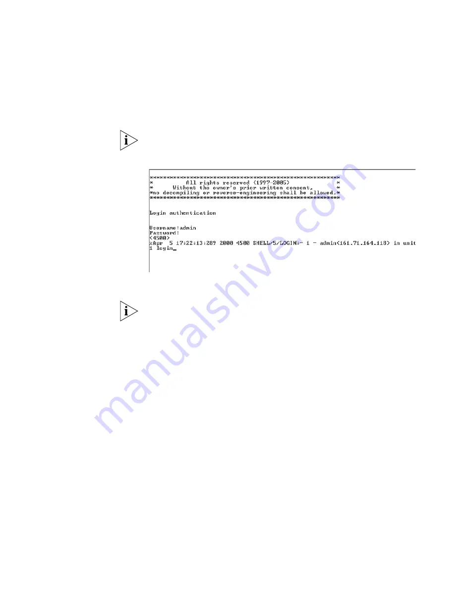
<4500>

 should be displayed as shown in Figure 16.

Once you have logged in you will automatically be in User View.

Figure 16   

User View Login

3

Enter the 

system-view

 command and 

Enter

.

To confirm that you are in the System View, the following should be 
displayed:


[4500] 

4

Enter 

interface vlan 1

 and 

Enter

.

5

Enter the IP address and subnet mask for the Switch as follows:

ip address xxx.xxx.xxx.xxx mmm.mmm.mmm.mmm 

and 

Enter

.

(where xxx.xxx.xxx.xxx is the IP address and mmm.mmm.mmm.mmm


is 

the subnet mask of the Switch)

6

Select the 

quit

 command and enter the default gateway for the Switch:

ip route-static 0.0.0.0 0.0.0.0 xxx.xxx.xxx.xxx

(where xxx.xxx.xxx.xxx is the IP address of the default gateway)

7

From the User View, enter the 

save

 command to save the configuration 

to your Switch as the configuration is not saved automatically when the 
Switch is powered down.

The initial set up of your Switch is now complete and the Switch is ready 
for you to set up your chosen management method. See “Methods of 
Managing a Switch” on page 38. 

Summary of Contents for ProCurve E4500-48

Page 1: ...3Com Switch 4500 Family Getting Started Guide Switch 4500 26 Port Switch 4500 50 Port Switch 4500 PWR 26 Port Switch 4500 PWR 50 Port www 3Com com Part No 10012034 Rev AB Published April 2007...

Page 2: ...252 227 7015 Nov 1995 or FAR 52 227 14 June 1987 whichever is applicable You agree not to remove or deface any portion of any legend provided on any licensed program or documentation contained in or d...

Page 3: ...igabit Ports 15 Console Port 16 Unit LED 17 LEDs 17 Switch 4500 Rear View Detail 19 Power Socket 19 Open Book Warning Labels 19 Redundant Power System Socket 20 Default Settings 20 2 INSTALLING THE SW...

Page 4: ...39 SNMP Management 39 Setting Up Overview 40 IP Configuration 41 Preparing for Management 42 Manually Configuring IP Information 43 Connecting to the Console Port 43 Connecting to a Front Panel Port 4...

Page 5: ...n Problems 69 6 UPGRADING SOFTWARE The Contents of the Executable File 72 Upgrading from the Command Line Interface 72 Introduction 72 Backup 74 TFTP 74 FTP via a network port 76 XModem via the consol...

Page 6: ...0 50 Port 92 Switch 4500 PWR 26 Port 93 Switch 4500 PWR 50 Port 94 RPS 95 Earthing Lead 95 C OBTAINING SUPPORT FOR YOUR PRODUCT Register Your Product 97 Purchase Value Added Services 97 Troubleshoot O...

Page 7: ...setting up network equipment consequently it assumes a basic working knowledge of LANs Local Area Networks Before You Start The Release Notes provide important information about the current software...

Page 8: ...ide provides detailed information about the web interface and command line interface that enable you to manage the Switch Release Notes These notes provide information about the current software relea...

Page 9: ...page Page number if appropriate Example Part Number 10015034 Rev AB Switch 4500 Family Getting Started Guide Page 21 We can only respond to comments and questions about 3Com product documentation at t...

Page 10: ...10 ABOUT THIS GUIDE...

Page 11: ...oductory information about the Switch 4500 and how it can be used in your network It covers summaries of hardware and software features and also the following topics About the Switch 4500 Switch 4500...

Page 12: ...to a backbone or for server connections With stacking you can add additional Switch 4500s as your network grows while preserving ease of management For information about using the software features o...

Page 13: ...er over Ethernet Supported on 10 100 ports 3CR17571 91 and 3CR17572 91 only Ethernet and Fast Ethernet Ports Auto negotiating 10BASE T 100BASE TX ports Gigbait Ethernet Ports Auto neogotiating 10BASE...

Page 14: ...Two pairs of Combo Ports fitted with two1000BASE T SFP transceivers in last two ports Unit LED Console Port Mode LED Power LED 10 100BASE TX Ports Port Status LEDs 1000Base X SFP Ports Two pairs of Co...

Page 15: ...the Switch 4500 26 Port and PWR 26 Port are 25 and 27 26 and 28 The paired ports for the Switch 4500 50 Port and PWR 50 Port are 49 and 51 50 and 52 By default the ports are enabled as follows for th...

Page 16: ...transceivers to provide connectivity between the Switch and remote 1000 Mbps workgroups The default state for these ports is auto negotiation enabled where the speed duplex and flow control modes are...

Page 17: ...rs in the Unit LED seven segment display or Software download is in progress During software download a clockwise cycling bar appears in the Unit LED Green flashing The Switch has failed POST The Unit...

Page 18: ...ow Half duplex blinking off for every packet received or transmitted Yellow flashing The port has failed POST Off No link is present PoE 3CR17571 91 and 3CR171572 only Green Power is being delivered t...

Page 19: ...500 ou d entamer une proc dure de maintenance lisez les informations relatives la s curit qui se trouvent dans l annexe A de ce guide VORSICHT Bevor Sie Komponenten der Switch 4500 Baureihe installier...

Page 20: ...4w on all ports and redundant power for powered devices and the Switch itself Default Settings Table 5 shows the default settings for the Switch 4500 Family Table 5 Default Settings Feature Switch 450...

Page 21: ...21 Traffic Prioritization All ports prioritize NBX VoIP traffic LAN and IP All ports set to best effort for all other traffic Port Security Disabled per port Configuration Save and Restore Disabled Fe...

Page 22: ...22 CHAPTER 1 INTRODUCING THE SWITCH 4500 FAMILY...

Page 23: ...ge Contents Switch unit Unit Information Labels Warranty Information RPS Flyer Power Cord Console Cable RJ 45 RPS 48V DC Connector and backshell 3CR17571 91 and 3CR17572 91 only RPS Connector Cable Ti...

Page 24: ...tend to use this DC connection please read this section WARNING The installation of the Redundant Power Supply RPS should only be carried out by properly trained and qualified personnel WARNING These...

Page 25: ...your Switch 4500 PWR 25 with the 3Com Power over Ethernet PoE network switches In order to meet the IEEE 802 3af PoE specification the 48V output must be isolated from earth ground and meet the isolat...

Page 26: ...rom the mains supply unit a failure of the internal power supply will cause the Switch to fail This can be overcome by connecting both the AC and DC RPS supplies to the Switch Additional redundancy ca...

Page 27: ...r will not affect the 48V DC output voltage Table 7 shows an example of the total power available from a number of 1500W rectifiers A minimum of two rectifiers are required for each shelf to provide N...

Page 28: ...switches Each RPS consists of a shelf which can house from one to six rectifiers a Distribution Module and a Management Module Connecting the Switch to the Redundant Power System When connecting the R...

Page 29: ...terminal on the Switch is connected to the negative circuit breaker terminal of the RPS Figure 7 shows how to connect the power supply to the RPS socket in the back of the Switch Use the cable tie su...

Page 30: ...0 100 ports over a Category 5 or Category 5e Ethernet cable The same cable connects the device to the network Power over Ethernet is a self configuring protocol When you plug a PoE compliant device in...

Page 31: ...upply increasing its uptime The Switch supports resistor detection according to IEEE 802 3af and pre standard detection methods The Switch 4500 supports 3Com 802 3af equipment For the latest list of s...

Page 32: ...uring the POST When the POST has completed check the PWR LED to make sure that your Switch is operating correctly Table 10 shows possible colors for the LED Table 10 Unit Status Colors If there is evi...

Page 33: ...onnectors and supports segment lengths of up to 100 m 328 ft Table 14 shows the range for each connection Table 11 1000BASE X SFP Port Cable Range Fiber Type Diameter microns Modal Bandwidth MHz km Tr...

Page 34: ...e correct cable type as follows 1000BASE SX SFP transceiver Use this transceiver to connect Gigabit Ethernet SFP ports on the Switch directly to a multimode fiber optic cable 1000BASE LX SFP transceiv...

Page 35: ...position 3 Gently slide the transceiver into the SFP port until it clicks If the transceiver does not click into place remove it turn it over and re insert 4 Remove the plastic protective cover if fi...

Page 36: ...your unit correctly 1 Orientate your Switch so that the back panel is on the left side looking down at the top of the unit as shown in Figure 9 2 Secure one of the polystyrene supports to the back pa...

Page 37: ...l performance of your network This chapter explains the initial set up of the Switch and the different methods of accessing the management software to manage a Switch It covers the following topics Me...

Page 38: ...k see Figure 11 Figure 10 CLI Management via the Console Port Figure 11 CLI Management over the Network Refer to Setting Up Command Line Interface Management on page 52 There are two main views in the...

Page 39: ...al set of web pages that allow you to manage the Switch using a Web browser remotely over an IP network see Figure 12 Figure 12 Web Interface Management over the Network Refer to Setting Up Web Interf...

Page 40: ...Feature Management Power Up the Switch IP Information is automatically configured via DHCP See page 41 Do you want to manually configure the IP information Connect to the con sole port and use the Co...

Page 41: ...esses Static IP addresses are necessary to ensure that the Switch is always allocated the same IP information For most installations 3Com recommends that you configure the Switch IP information manual...

Page 42: ...itch is not allocated with an automatic IP address the IP configuration will be blank or shown as If you use the automatic IP configuration method you need to discover the automatically allocated IP i...

Page 43: ...nnection to the console port this example describes a local connection to the console port rather than one via a modem You can do this whilst the Switch is offline that is before you connect the Switc...

Page 44: ...ble The settings must be set to match the default settings for the Switch which are 19 200 baud bits per second 8 data bits no parity 1 stop bit no hardware flow control Refer to the documentation tha...

Page 45: ...address and subnet mask for the Switch as follows ip address xxx xxx xxx xxx mmm mmm mmm mmm and Enter where xxx xxx xxx xxx is the IP address and mmm mmm mmm mmm is the subnet mask of the Switch 6 S...

Page 46: ...mation on page 49 for more information The procedure described in this section assumes the unit has been powered up in standalone mode Pre requisites A workstation running a suitable operating system...

Page 47: ...nually set up the Switch with IP information You can do this using the Web interface or the command line interface CLI via telnet Using the Web Interface 1 Power up the Switch This takes approximately...

Page 48: ...et up your chosen management method See Methods of Managing a Switch on page 38 Using Command Line Interface via Telnet 1 To start a Telnet session to the unit click Start in Microsoft Windows 95 98 2...

Page 49: ...ser View enter the save command to save the configuration to your Switch as the configuration is not saved automatically when the Switch is powered down The initial set up of your Switch is now comple...

Page 50: ...DHCP or BootP server If your network does not have a DHCP or BootP server the workstation running 3Com Network Director must be on the same subnet as the Switch because Auto IP addresses are non routa...

Page 51: ...ayed as shown in the example in Figure 19 Figure 19 User View Login 4 Enter display ip interface br to view a summary of allocated IP addresses The initial set up of your Switch is now complete and th...

Page 52: ...to the Console Port on page 43 2 Your Switch is now ready to continue being managed and or configured through the CLI via its console port CLI Management over the Network To manage a Switch using the...

Page 53: ...ing SSH 1 Ensure you have already set up the Switch with IP information as described in Methods of Managing a Switch on page 38 2 Check that you have the IP protocol correctly installed on your manage...

Page 54: ...e Switch using TFTP server please refer to the Configuration Guide that is supplied with your Switch Setting Up Web Interface Management This section describes how you can set up web interface managem...

Page 55: ...ch is powered up 3 Open your web browser and enter the IP address of the Switch that you wish to manage in the URL locator for example in the following format http xxx xxx xxx xxx 4 At the login and p...

Page 56: ...enu in System View Default Users and Passwords If you intend to manage the Switch using the web interface or the command line interface or to change the default passwords you need to log in with a val...

Page 57: ...d for the admin user in the CLI enter the following from system view 4500 local user admin cr 4500 luser admin password simple xxxxxxxx where xxxxxxxx is your chosen password Save the configuration in...

Page 58: ...58 CHAPTER 3 SETTING UP FOR MANAGEMENT...

Page 59: ...ch 4500s This section assumes you have either set up your units for management as detailed in Chapter 3 Setting Up for Management or that you are using a console cable connected to the console port to...

Page 60: ...nected is eight You can only create a stack by interconnecting a 3Com Switch 4500 with other 3Com Switch 4500s Stacking is only supported using Gigabit ports The stacking connections must be from one...

Page 61: ...Com recommends that you manually assign the unit IDs within the stack if you wish to have predictability of knowing which units have which IDs at all times Stack topology is discovered and the units a...

Page 62: ...g only occurs when the stack is next power cycled if the units are configured to auto number The unit LEDs will display the unit number in the stack from 1 to 8 If you are having problems refer to Sol...

Page 63: ...ware The topics covered are Solving Problems Indicated by LEDs Solving Hardware Problems Solving Communication Problems Solving Stack Formation Problems If you experience a problem that is not listed...

Page 64: ...blem The fault type will be indicated on the unit LEDs Contact your supplier for advice On powering up the PWR LED is flashing yellow A port has failed and has been automatically disabled You can veri...

Page 65: ...could potentially reduce the lifetime of the Switch The monitoring system polls the fan status at periodic intervals while the unit is powered up If one fan has failed in the Switch a warning message...

Page 66: ...return the unit If yes check that The air vents are not obstructed The ambient temperatures and environmental conditions meet those specified in Appendix B 4 Power cycle the unit If a further thermal...

Page 67: ...where n is a decimal number between 0 and 255 An example IP address is 192 168 100 8 The IP address is split into two parts The first part 192 168 100 in the example identifies the network on which th...

Page 68: ...d ref 18 The 4500 PWR will only supply power through the front panel port to 802 3af compliant devices Check that power budget for the Switch has not been exceeded If the power budget has been exceede...

Page 69: ...g problems with correctly forming a stack first ensure that Spanning Tree is enabled If it is enabled do the following 1 Power off all units in the stack 2 Check all the cable connections in the stack...

Page 70: ...70 CHAPTER 5 PROBLEM SOLVING...

Page 71: ...chapter describes how to upgrade software to your Switch 4500 It covers the following topics The Contents of the Executable File Upgrading from the Command Line Interface Upgrading from the Bootrom I...

Page 72: ...xxxNetMan zip will fail The individual web btm or app files should be used to upgrade your Switch as described below The Switch 4500 ships with software supporting 56 bit encryption Check on www 3Com...

Page 73: ...o delete a file from the list enter delete unreserved unit1 flash filename To delete files from the list for the remaining units in a fabric replace unit1 with unit2 on the next line and so on for eac...

Page 74: ...flash 030100cfg cfg Replace unit1 with unit2 and so on for each Switch in the fabric 3 To back up the Web user interface file on each Switch in the fabric enter copy unit1 flash s3p03_01_00 web unit1...

Page 75: ...lace unit2 with unit3 and so on for each Switch in the fabric 2 To copy the new default configuration file to each Switch in the fabric enter copy unit1 flash 3ComOScfg def unit2 flash Replace unit2 w...

Page 76: ...rom firmware and boot from the specified software app file The files that you have saved in the backup phase should be deleted once the upgrade has completed successfully FTP via a network port To upg...

Page 77: ...splayed WARNING xmodem is a slow transfer protocol limited to the current speed settings of the auxiliary ports During the course of the download no exec input output will be available Proceed Y N y D...

Page 78: ...sword to display the following boot menu BOOT MENU 1 Download application file to flash 2 Select application file to boot 3 Display all files in flash 4 Delete file from flash 5 Modify bootrom passwor...

Page 79: ..._0024 zip 3comoscfg def 3comoscfg cfg s3n03_01_00s168 app The s3n03_01_00s168 app file is the boot software The name of this file will vary depending on the Switch type and the release version If the...

Page 80: ...le to flash Yes or No Y N 4 Enter y and the following information is displayed to indicate the file is downloading Attached TCP IP Interface to netdrv0 Attaching network interface lo0 done Loading don...

Page 81: ...h of the remaining files XModem To upgrade software to your Switch via XModem do the following 1 From the Boot Menu select option 1 Download application file to flash to display the following 1 Set TF...

Page 82: ...e software has been loaded 1 From the Boot menu select option 2 to display the following Select applicaton file to boot 1 set application file to boot 2 set configuration files 3 set web files 0 retur...

Page 83: ...address and Server IP address to display the following Are you sure to update your bootrom Yes or No Y N 4 Enter y and the following information is displayed to indicate the file is downloading Attac...

Page 84: ...e Loading done Bootrom updating done Bootrom Upgrade via XModem To upgrade the bootrom firmware from the Boot menu via XModem do the following 1 From the Boot Menu select option 6 to display the follo...

Page 85: ...rotocol If you want to exit Press Ctrl X Loading CCCCCCCCCCCCCCCCCCCCCCCCCCCCC 5 As the file is downloading start the XModem send file process with terminal emulation software such as Microsoft Hypert...

Page 86: ...86 CHAPTER 6 UPGRADING SOFTWARE...

Page 87: ...PC Terminal Cable connector 25 pin male female only required if screen always required required for handshake Screen DTR TxD RxD CTS Ground DSR RTS DCD Screen DCD RxD TxD DTR Ground DSR RTS CTS Shell...

Page 88: ...8 6 5 1 4 1 2 3 4 5 6 7 8 20 Switch 4500 Cable connector RJ 45 female RS 232 Modem Port Cable connector 25 pin male Pin Number 10 100 1000 Ports configured as MDI 1 Transmit Data Bidirectional Data A...

Page 89: ...ed as MDIX 1 Receive Data Bidirectional Data B 2 Receive Data Bidirectional Data B 3 Transmit Data Bidirectional Data A 4 Not assigned Bidirectional Data A 5 Not assigned Bidirectional Data D 6 Transm...

Page 90: ...90 APPENDIX A PIN OUTS...

Page 91: ...tandards EN60068 to 3Com schedule Package testing paras 2 1 2 2 2 30 and 2 32 Operational testing paras 2 1 2 2 2 30 and 2 13 Safety Agency Certifications UL 60950 EN60950 CSA 22 2 No 60950 IEC 60950...

Page 92: ...tandards EN60068 to 3Com schedule Package testing paras 2 1 2 2 2 30 and 2 32 Operational testing paras 2 1 2 2 2 30 and 2 13 Safety Agency Certifications UL60950 EN60950 CSA 22 2 No 60950 IEC 60950 E...

Page 93: ...Agency Certifications UL60950 EN60950 CSA 22 2 No 60950 IEC 60950 EMC Emissions CISPR 22 Class A EN55022 Class A FCC Part 15 Subpart B Class A ICES 003 Class A VCCI Class A EN61000 3 2 EN61000 3 3 Im...

Page 94: ...afety Agency Certifications UL60950 EN60950 CSA 22 2 No 60950 IEC 60950 EMC Emissions CISPR 22 Class A EN55022 Class A FCC Part 15 Subpart B Class A ICES 003 Class A VCCI Class A EN61000 3 2 EN61000 3...

Page 95: ...k Login IEEE 802 1x RADIUS RFC 2618 2620 Link aggregation IEEE 802 3ad Safety Requirements The RPS shall comply with the following safety standards EN60950 UL60950 CSA22 2 60950 IEC60950 EMC Emissions...

Page 96: ...96 APPENDIX B TECHNICAL SPECIFICATIONS...

Page 97: ...Request If you have trouble registering your product please contact 3Com Global Services for assistance Purchase Value Added Services To enhance response times or extend warranty benefits contact 3Co...

Page 98: ...ct Support heading at http www 3com com Software Upgrades are the software releases that follow the software version included with your original product In order to access upgrades and related documen...

Page 99: ...irectory of contact information posted on the 3Com web site at http csoweb4 3com com contactus Country Telephone Number Country Telephone Number Asia Pacific Rim Telephone Technical Support and Repair...

Page 100: ...2 1 800 998 2112 52 5 201 0010 1 800 998 2112 1 800 998 2112 0800 13 3COM 1 800 998 2112 AT T 800 998 2112 AT T 800 998 2112 AT T 800 998 2112 1 800 998 2112 AT T 800 998 2112 AT T 800 998 2112 Guatem...

Page 101: ...Ds 17 logging in as a default user 56 M management methods 38 preparing for 42 setting up 37 40 manual setup console port 43 front panel port 46 P passwords of default users 56 pin assignments modem c...

Page 102: ...ons 91 T troubleshooting 63 71 U upgrading software bootrom 78 bootrom via FTP 83 bootrom via TFTP 83 bootrom via XModem 84 file distribution 75 FTP 76 80 TFTP 74 80 XModem 77 81 W Web browsers choosi...

Reviews: