background image


5-4 

Figure 5-1 

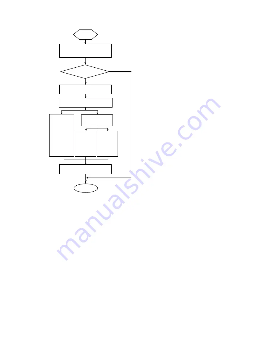
Upgrade BootROM and Comware under Comware V5 environment 

Comware  version

Start

End

Upgrade Comware  ?

Choose  upgrade mode

Xmodem 

upgrade

TFTP 

upgrade

FTP 

upgrade

Choose  correct  Comware

N

Y

Upgrade

Via  network 

interface


BootROM Menu 

Main BootROM Menu 

When the router is powered on and reboots, the console terminal displays: 

InitDDR 

Proceed to boot, and the system prompts: 

system start booting......Version  2.11 

Press CTRL+D to stop auto-boot 

Booting Normal Extend BootRom 

Decompressing...done! 

Ensure the baudrate is set to 9600bps!Starting at 0xa00000... 


      ******************************************************* 

      *                                                     * 

      *             MSR50-40 BOOTROM, Version 2.11          * 

      *                                                     * 

Summary of Contents for MSR 50-40

Page 1: ...H3C MSR 50 Series Routers Installation Manual Hangzhou H3C Technologies Co Ltd http www h3c com Manual Version T2 08047M 20081106 C 1 03 ...

Page 2: ... V2 G Vn G PSPT XGbus N Bus TiGem InnoVision and HUASAN are trademarks of Hangzhou H3C Technologies Co Ltd All other trademarks that may be mentioned in this manual are the property of their respective owners Notice The information in this document is subject to change without notice Every effort has been made in the preparation of this document to ensure accuracy of the contents but all statement...

Page 3: ...intain BootROM menu and software of the MSR 50 series 6 Hardware Maintenance Introduces how to install and remove SDRAM ESM VCPM card and CF card of the MSR 50 series 7 Troubleshooting Describes some problems that may arise and how to solve them Conventions The manual uses the following conventions Command conventions Convention Description Boldface The keywords of a command line are in Boldface i...

Page 4: ...quare brackets For example pop up the New User window Multi level menus are separated by forward slashes For example File Create Folder Symbols Convention Description Means reader be extremely careful Improper operation may cause bodily injury Means reader be careful Improper operation may cause data loss or damage to equipment Means a complementary description ...

Page 5: ...e MSR 20 Series Routers and how to install hardware configure and boot software and maintain software and hardware This guide also provides troubleshooting and support information for your router MSR 50 Series Routers Installation Manual This guide describes the MSR 30 Series Routers and how to install hardware configure and boot software and maintain software and hardware This guide also provides...

Page 6: ...ments Environmental Protection This product has been designed to comply with the requirements on environmental protection For the proper storage use and disposal of this product national laws and regulations must be observed ...

Page 7: ...Requirements on Electromagnetic Environments 2 2 Requirements on Preventing Lightning 2 3 Requirements on Workbench 2 3 Safety Precautions 2 3 Installation Tools Meters and Equipments 2 4 3 Installation 3 1 Installation Process 3 1 Installing the Cabinet 3 2 Installing the Router 3 2 Installing the Router on a Workbench 3 2 Installing the Router in a Rack 3 2 Installing Generic Modules 3 3 Connect...

Page 8: ...gram Through Serial Port 5 12 Upgrading Application Program Through Ethernet Interface 5 12 Configuring Ethernet Parameters 5 12 Upgrading Application Program Through Ethernet Interface 5 14 Maintaining Application Program and Configuring Through Command Lines 5 16 Maintaining the Router with TFTP Server 5 16 Maintaining the Router with FTP Server 5 18 Maintaining Application Program and Configura...

Page 9: ...ard 6 7 Replacing Memory Bar 6 8 Memory Bar Structure 6 9 Memory Bar Slot 6 9 Installing Removing Memory Bar 6 9 Replacing VPM 6 10 VPM Structure 6 10 VPM Slot 6 11 Installing Removing VPM 6 11 Installing Removing ESM VCPM Card 6 11 7 Troubleshooting 7 1 Troubleshooting the Power System 7 1 Troubleshooting the Configuration System 7 1 Troubleshooting Application Software Upgrade 7 2 ...

Page 10: ...Interface 1 1 Interface Card 1 1 Processor and Memory 1 2 Other Hardware Specifications 1 2 MSR 50 40 50 60 Routers 1 3 Generic Modules 1 5 MPUF 1 5 MSCA 1 11 PSU 1 12 FAN Module 1 13 SIC DSIC and FIC DFIC Interface Cards 1 14 ESM Module 1 14 Voice Module 1 15 ...

Page 11: ...service card A MSCA enhanced service module ESM voice processing module VPM and voice co processing module VCPM Base on power supply mode the MSR 50 40 and MSR 50 60 each have two models AC DC You can choose to use a DC or AC power supply unit PSU as the system power supply or install two AC or two DC PSUs to form 1 1 redundancy backup The PSUs fan trays and FICs of MSR 50 series routers are all h...

Page 12: ...card is used to store the software system and configuration file The CF card LED blinks when the system is reading writing data from to the CF card In this case do not remove the CF card otherwise hardware and software damage may occur Other Hardware Specifications Table 1 4 Specifications description of other hardware Item MSR 50 40 Description MSR 50 60 Description Dimensions H W D excluding fee...

Page 13: ... card LED 2 CF card 3 SIC slot 1 4 SIC slot 2 5 SIC slot 3 6 SIC slot 4 7 FIC slot 5 8 FIC slot 6 9 FIC slot 7 10 FIC slot 8 2 Rear view of MSR 50 40 Figure 1 2 Rear view of MSR 50 40 1 3 2 5 6 4 1 MSCA slot 2 System power 1 slot 3 System power 0 slot 4 System power socket 5 Grounding terminal 6 Fan slot 3 Front view of MSR 50 60 ...

Page 14: ...ot 2 5 SIC slot 3 6 SIC slot 4 7 FIC slot 5 8 FIC slot 6 9 FIC slot 7 10 FIC slot 8 11 FIC slot 9 12 FIC slot 10 4 Rear view of MSR 50 60 Figure 1 4 Rear view of MSR 50 60 1 3 2 6 7 5 4 1 MSCA slot 2 System power 2 slot 3 System power 1 slot 4 System power 0 slot 5 System power socket 6 Grounding terminal 7 Fan slot ...

Page 15: ...ctions to process protocols forward low speed packets govern interfaces and detect faults You can gather information about the operating state of FAN module PSU and system by reading their corresponding LEDs on the main control board alternatively you can monitor state using a network management system In addition the main control board provides a hardware reset button RESET Appearance Figure 1 5 ...

Page 16: ...3 MHz BootROM 4 MB DDR SDRAM Default 512 MB Max 1 GB CF Card Default 256 MB Max 1 GB Slot 4 SIC slots z DDR SDRAM synchronous dynamic random access memory is the memory z CF card functions as the major file storage medium to store application program files anomaly information and configuration files z BootROM stores bootstrap files LED and interface Figure 1 7 LEDs and interfaces ...

Page 17: ...port CONSOLE 20 Auxiliary port AUX 21 Fixed gigabit electrical interface 0 22 Fixed gigabit electrical interface 1 23 Fixed gigabit optical interface 0 24 Fixed gigabit optical interface 1 25 RESET LED 1 LED attributes Table 1 6 LED attributes LED Color Number Status Meaning Off No power input or the main control board has failed Green blinking 0 5 Hz The interface card is running as configured Gr...

Page 18: ...ng SFP optical module is transmitting or receiving data SFP0 1 Green yellow 2 Yellow SFP has not passed the test Off No CF card Steady green CF card is present and can be identified by the router Green blinking The system is accessing the CF card In this case the card cannot be removed CF Green Yellow 1 Yellow CF card cannot be identified by the router Off USB is not connected to HOST Steady green...

Page 19: ...nd running terminal emulation program on the PC Command line interface 3 AUX port Table 1 8 AUX port attributes Attribute Description Connector RJ 45 Interface standard RS232 Baud rate 300 bps to 115200 bps Function Modem dialup Backup 4 Ethernet interface The MPUF provides two 10 100 1000 Mbps Ethernet interfaces that each accommodates an RJ 45 connector and a small form factor pluggable SFP modu...

Page 20: ... Connector SFP LC Optical fiber 62 5 125 μm multi mode 9 125 μm single mode 9 125 μm single mode 9 125 μm single mode 9 125 μm single mode Max transmission segment 0 55 km 0 34 mi 10 km 6 21 mi 40 km 24 86 mi 40 km 24 86 mi 70 km 43 50 mi Central wavelength 850 nm 1310 nm 1310 nm 1550 nm 1550 nm Min 9 5 dBm 9 dBm 2 dBm 4 dBm 4 dBm Transmit ter optical power Max 0 dBm 3 dBm 5 dBm 1 dBm 2 dBm Receiv...

Page 21: ...ent Do not remove a CF card during its read or write operation otherwise data loss and even hardware damage will occur 6 USB interface MPUF provides two USB 1 1 interfaces USB1 for Host and USB0 for Host and Slave that can be configured USB LED is valid only when USB0 is set to Slave MSCA Appearance Figure 1 9 MSCA front view Figure 1 10 MSCA internal structure Specifications Table 1 11 MSCA speci...

Page 22: ...he encryption card functions to encrypt packets Table 1 12 Encryption card attributes Attribute Description Protocol IPSec Hardware encryption algorithm Key algorithms DES 3DES AES Authentication algorithms HMAC MD5 96 HMAC SHA 1 96 VPM and VCPM modules VPM Voice Processing Module functions to coding decoding EC and CNG of voices VCPM Voice Co Processing Module processes the voice data together wi...

Page 23: ... ON means the normal voltage is inputting and OFF means the opposite FAN Module Functions The MSR 50 40 is configured with six fans the MSR 50 60 is configured with eight fans These fans are working in pairs and the two fans in each pair are working in redundancy When all these fans are working normally the operating temperature of the system can be maintained between 0 C and 55 C 32 F to 131 F As...

Page 24: ...itching interface and so on For details about the interface cards refer to MSR Series Routers Interface Card and Interface Module Manual For an MSR 50 series router 4FSW 1FEA 1GEC 1ADSL 1ADSL I can only be installed in Slot 2 or Slot 4 ESM Module z High performance network data encryption ESM module ESM ANDE z Standard network data encryption ESM module ESM SNDE ESM module supports IPSec and by us...

Page 25: ...Module VPM Voice Processing Module functions to implement the encryption decryption EC and CNG of voices VCPM Voice Co Processing Module processes the voice data together with VPM z Voice co processing module RT VCPM z 8 channel voice processing module RT VPM8 z 16 channel voice processing module RT VPM16 z 24 channel voice processing module RT VPM24 z 32 channel voice processing module RT VPM32 ...

Page 26: ...n Temperature Humidity 2 1 Requirements on Cleanness 2 1 Requirements on Electrostatic Discharge Prevention 2 2 Requirements on Electromagnetic Environments 2 2 Requirements on Preventing Lightning 2 3 Requirements on Workbench 2 3 Safety Precautions 2 3 Installation Tools Meters and Equipments 2 4 ...

Page 27: ...ectricity may be produced putting the CMOS of the router to risk High temperature is of the greatest risk for it will significantly degrade the router s reliability speed up aging process of the insulating materials and shorten the service life of the router The requirements on the temperature and humidity for MSR 50 Series are shown in the following table Table 2 1 Temperature humidity requiremen...

Page 28: ...SD z Make sure that the equipment and the floor are well grounded z The equipment room is dust proof z Maintain an appropriate humidity and temperature z Wear an ESD preventive wrist strap and uniform when contacting the circuit board z Place the removed circuit board on the antistatic workbench with its face upward or put it into the static shielding bag z When observing or moving the removed cir...

Page 29: ... system z Make sure that the rack is sturdy enough to support the weight of the device and the installation accessories z Make sure that the rack is well grounded Safety Precautions When reading this manual please pay attention to the following It indicates that this operation is incorrect and may seriously damage the router or endanger the operator Please follow the correct operation procedures f...

Page 30: ...D preventive twist strap Cables z PGND wire and power cord z Console cable z Optional cables Meters and equipment z Hub or LAN switch z Console terminal it could be a PC z Equipment related to the selected modules z Multimeter MSR 50 series was not shipped with any installation tools meters or devices ...

Page 31: ...onnecting the PGND 3 3 Connecting the Power Cord 3 4 Power Input and PGND 3 4 Connecting the AC Power Cord 3 4 Connecting the DC Power Cord 3 5 Connecting the Console Terminal 3 6 Fixed Interfaces 3 7 Ethernet Interface 3 7 Connecting AUX to a Modem 3 10 Interface Card Module 3 11 Installing Removing Slide Rail 3 11 MSR 50 Series Slide Rail 3 11 Installing Slide Rail 3 12 Removing Slide Rail 3 13 ...

Page 32: ...n Connect to the WAN Connect to the Ethernet Install multifunctional interface modules End Pow eron Pow eron Verify installation Connect to the console terminal Connect the power cord Connect PGND Start Mount the rack Normal NO YES Troubleshoot Install the FICs Turnoff thepow er sw itch Turn off the pow erswitch ...

Page 33: ...ch z Leave a space of 10 cm 3 9 in around the router for heat dissipation z Do not place heavy objects on the router Installing the Router in a Rack Dimensions MSR 50 Series Routers are designed according to the dimensions of 19 inch standard rack as follows Table 3 1 MSR 50 40 50 60 Router dimensions Router model Dimensions H W D excluding feet and rack mounting ear MSR 50 40 130 7 436 2 424 mm 5...

Page 34: ...l safeguard against the lightning shocks and interference You must correctly connect the PGND when installing or using the router As shown in the following figure the router provides a protection ground PGND screw at the top right rear of the chassis You must securely connect it to the earth ground to safely channel faradic current and leakage electricity to the ground and have the device less sus...

Page 35: ...ven the peer device Connecting the Power Cord Based on power supply mode the MSR 50 40 and MSR 50 60 each have two models DC AC You can choose suitable models as needed Power Input and PGND Table 3 2 Power input and PGND of the MSR 50 40 and MSR 50 60 routers Item Description Power input AC powered Provide 100 VAC to 240 VAC power socket Power input DC powered Provide 60 VDC to 48 VDC power socket...

Page 36: ...at the PGND is securely connected to the earth ground Step 2 Insert one end of the power cord accompanying the router into the power socket on the chassis rear panel and fix the cable onto the cable retention clip with a cable strap Connect the other end of the cable to an AC power source at your installation site Step 3 Place the power switch of the router to the ON position Step 4 Check that the...

Page 37: ... supply When connecting the DC power cord notice the labels on the power cord to avoid wrong connection Step 3 Place the power switch of the router to the ON position Step 4 Check the POWER LED on the front panel of the router ON indicates correct connection Connecting the Console Terminal Console port MSR 50 series provides an RS232 asynchronous serial console CON port through which you can compl...

Page 38: ...al to the console port on the router through the console cable Verify the connection and power up the devices The console terminal shows the startup information of the router if the connection is correct Fixed Interfaces Ethernet Interface 1000 Mbps Ethernet interface MSR 50 Series Routers are available with fixed 1000 Mbps Ethernet COMBO interface and Ethernet modules cards for expansion For more...

Page 39: ...nsitivity 17 dBm 20 dBm 23 dBm 21 dBm 22 dBm Operating mode 1000 Mbps Full duplex Frame format Ethernet_II Ethernet_SNAP z The fiber optic and electrical connections that a 10 100 1000 Mbps Ethernet interface provides cannot be used at the same time If both connections are present you can configure which connection takes effect through commands By default the electrical connection works z MDI medi...

Page 40: ...ompatibility sake 2 Optical Ethernet interface cable For the 10 100 1000 Mbps optical Ethernet interfaces select single mode or multi mode optical fibers depending on the type of the installed 1000Base X SFPs As the interfaces that these SFP modules provide use LC type fiber optic connectors you must use fibers with LC type connectors for them All these SFPs are hot swappable SFPs are optional The...

Page 41: ...es against radiation harm never stare into an open fiber optic port Follow these steps to connect a 10 100 1000 Mbps optical interface Step 1 Use two fibers to connect the Rx and Tx ends of the interface to another device Rx to Tx and Tx to Rx Step 2 Power on the router and view the LINK LED of the Ethernet interface ON means the Rx link is present OFF means no Rx link is present check the line fo...

Page 42: ...uration or dial backup you need to connect the local modem to the remote modem through PSTN and then to the remote device For the configuration procedures refer to MSR 20 30 50 Series Routers User Manual Interface Card Module The MSR 50 Series Routers are available with various types of interface card modules For detailed information refer to MSR 20 30 50 Series Routers Interface Card and Interfac...

Page 43: ...3 12 FIC slide rail Figure 3 11 FIC slide rail Installing Slide Rail Figure 3 12 Install an FIC slide rail Figure 3 13 Installation finished ...

Page 44: ...external force when you install a DFIC thus the DFIC on the other side cannot be installed normally You can right the rail manually and then install the DFIC normally z When installing a DFIC it is recommended that you fasten the release screw first and then install the DFIC M on the other side of the rail Removing Slide Rail Figure 3 14 Unfasten the screw Figure 3 15 Remove the slide rail Refer t...

Page 45: ...orkbench is stable enough z The power supply that the power cord connects to is compliant with that required by the router z The PGND wire of the router is correctly connected z The router is correctly connected to other devices such as the console terminal The check after installation is very important The stability grounding of the router and power supply will directly affect the operation of th...

Page 46: ...ion 4 1 Startup 4 1 Setting up Configuration Environment 4 1 Powering on the Router 4 3 Startup Process 4 4 Configuration Fundamentals 4 5 Basic Configuration Procedures 4 6 Command Line Interface 4 6 Arranging Slots and Numbering Interfaces 4 7 ...

Page 47: ...e port on the router and DB 9 connector to the serial interface of a PC as shown in the following figure Figure 4 1 Local configuration through Console port ROUTER PC Console Setting the parameters for console terminal 1 Opening the console terminal and setting up a new connection Select the serial interface to be connected in the Connect using field in the Connect using box as shown in the follow...

Page 48: ...rity check stop bit to 1 and flow control to none Then click OK to return to the HyperTerminal window Figure 4 3 Set serial interface parameters 3 Set HyperTerminal properties Select File Properties Settings in the Hyper Terminal window to enter the aaa Properties window as shown in the following figure Select the terminal emulation type to be VT100 or Auto detect and click OK to return to the Hyp...

Page 49: ...gs are done z Whether the CF card is loosened Before powering on the router the user should be aware where the switch of the power supply to the router is located so that the power supply can be disconnected in time once accidents occur Powering on the router z Turn on the site power z Turn on the power switch of the router Checking operating after power on After powering on the router check that ...

Page 50: ...ters the program decompression process Enter Ctrl D within 3 seconds after the Press CTRL D to stop auto boot appears and the system enters basic BootROM menu otherwise the system enters the program decompression process of the extended BootROM menu Booting Normal Extended BootRom Decompressing done Ensure the baudrate is set to 9600bps Starting at 0xa00000 MSR50 40 BOOTROM Version 2 11 Copyright ...

Page 51: ... the decompression process you need to reboot the router The current starting file is main application file cf main bin The main application file is self decompressing Decompressing done System is starting Ensure the baudrate is set to 9600bps Starting at 0x10000 usrRoot end leave BSP id 0x2000 proc 0xd75bd0 DRV_Time_GetTimeZone return 1 DRV_Time_SetTimeZone return 1 id 0x70000 proc 0xd96bfc User ...

Page 52: ...ers User Manual for the configuration details of the protocols or functions of the router Basic Configuration Procedures Command Line Interface Characteristics of the command line interface The command line interface of MSR 50 Series Routers provides a number of configuration commands which can be used to configure and manage the router The command line interface has the following characteristics ...

Page 53: ...nterfaces are numbered Figure 4 5 Slot arrangement on the MSR 50 40 1 Slot 0 2 Slot 1 3 Slot 2 4 Slot 3 5 Slot 4 6 Slot 5 7 Slot 6 8 Slot 7 9 Slot 8 Figure 4 6 Slot arrangement on the MSR 50 60 1 4 5 6 2 3 7 8 9 10 11 1 Slot 0 2 Slot 1 3 Slot 2 4 Slot 3 5 Slot 4 6 Slot 5 7 Slot 6 8 Slot 7 9 Slot 8 10 Slot 9 11 Slot 10 Interface numbering The MSR 50 Series Router interface adopts two dimension numb...

Page 54: ...mber X z For every interface Y starts from 0 indicating the interface sequence on the interface module from left to right If you install an FIC 1FE and an FIC 2FE respectively in SLOT5 and SLOT6 on the MSR 50 40 the Ethernet interfaces are numbered as follows z The fixed GE interfaces are Gigabit Ethernet 0 0 and Gigabit Ethernet 0 1 z The Ethernet interface on the FIC 1FE is Ethernet 5 0 z The Et...

Page 55: ...ing Application Program Through Ethernet Interface 5 12 Configuring Ethernet Parameters 5 12 Upgrading Application Program Through Ethernet Interface 5 14 Maintaining Application Program and Configuring Through Command Lines 5 16 Maintaining the Router with TFTP Server 5 16 Maintaining the Router with FTP Server 5 18 Maintaining Application Program and Configuration File 5 21 Dealing with Router P...

Page 56: ...cure bin S z The application programs for system boot can be type M B and S but not type N You can store them in Flash memory but only one for each For example if an M B file exists it is impossible to have another M or B file If you change the file type of another file to B the M B file becomes a type M file z You can modify the file name of an application file in CF card using the command after ...

Page 57: ...ils to boot with the backup configuration file If the system fails to boot with the default configuration file it boots with null configuration The name of the default configuration file has something to do with the router brand The main and backup configuration operations on the default configuration file is the same with common configuration files z The configuration files for system boot can be...

Page 58: ...last character of the file name Two consecutive s are not allowed Software Maintenance Methods 1 Upgrading BootROM and application program using XModem protocol through serial port 2 Upgrading application program from TFTP FTP server through Ethernet interface in BootROM 3 Uploading downloading application program and configuration file from TFTP FTP server via command lines z BootROM program is u...

Page 59: ...mware N Y Upgrade Via network interface BootROM Menu Main BootROM Menu When the router is powered on and reboots the console terminal displays InitDDR Proceed to boot and the system prompts system start booting Version 2 11 Press CTRL D to stop auto boot Booting Normal Extend BootRom Decompressing done Ensure the baudrate is set to 9600bps Starting at 0xa00000 MSR50 40 BOOTROM Version 2 11 ...

Page 60: ...his manual except for special statement Press Ctrl B when it displays Press Ctrl B to enter extended boot menu Then the system prompts Please input Boot ROM password You have three chances to provide the correct BootROM password the initial setting is void If you fail to do that you need to reboot the system After you enter the correct password the console screen displays EXTEND BOOTROM MENU 1 Boo...

Page 61: ...emory device a Reboot Reboot the router BootROM Submenus Enter serial submenu This submenu can be used for upgrading application program changing serial baud rate and other operations Enter 2 under the main BootROM menu to enter the serial submenu SERIAL SUB MENU Note the operating device is CF Card 1 Download Application Program To SDRAM And Run 2 Update Main Application File 3 Update Backup Appl...

Page 62: ...submenu Menu item Description 1 Download Application Program To SDRAM And Run Download application program to SDRAM and run it 2 Update Main Application File Upgrade the main application file 3 Update Backup Application File Upgrade the backup application file 4 Update Secure Application File Upgrade the secure application file 5 Change Ethernet Parameter Modify Ethernet parameters 6 Exit To Main ...

Page 63: ...oot ROM With XModem 4 Update Extended Boot ROM With XModem 5 Update Basic Boot ROM With XModem 6 Exit To Main Menu Note When Update Full Extended Basic BootRom they are the same file Enter your choice 1 6 The submenu is defined as follows Table 5 7 BootROM operation submenu Menu item Description 1 Backup Full Boot ROM Backup full BootROM 2 Restore Full Boot ROM Restore full BootROM 3 Update Full B...

Page 64: ...Press Enter to exit with things untouched Baudrate Available 1 9600 Default 2 19200 3 38400 4 57600 5 115200 6 Exit Enter Your Choice 1 6 Select a baud rate 5 for 115200 bps for example The following prompt appears Change the baudrate on PC side first Since the router serial baud rate is modified to 115200 bps whereas the terminal baud rate remains to be 9600 bps they can not communicate with each...

Page 65: ...Enter to prompt current configuration baud rate and return to the previous menu The system prompts The current baudrate is 115200 Restore the baud rate in the HyperTerminal to 9600 bps the default after upgrading the BootROM This is to ensure that information can be displayed on the console screen after system boot or reboot ...

Page 66: ...ootROM operation menu The system prompts Select program file please Waiting CC Select Transfer Send file in the HyperTerminal window The following window pops up Figure 5 5 Send File dialog box In the displayed Send File dialog box click Browse to select the application program file to be downloaded and select XModem for the Protocol field Then click Send The following interface appears Figure 5 6...

Page 67: ...ort Parameters for details and then enter 2 under serial submenu The system prompts Select program file please Waiting CC Select application program file and send it Upgrading application program with serial port takes the similar steps with upgrading BootROM Refer to section Upgrading BootROM for details Application program often takes over 10M Even if the baud rate is changed to 115200 bps the u...

Page 68: ... downloading path in FTP and TFTP settings inet on ethernet e Set it to be in the same network with TFTP FTP server It has nothing to do with port IP address of the router Separate the mask from the IP address if a mask is needed for example 192 168 80 10 24 inet on backplane b Backplane address no need to set host inet h IP address of the FTP or TFTP server gateway inet g Gateway IP address no ne...

Page 69: ...ization and authentication mechanism It employs timeout retransmission to guarantee the successful transferring of data TFTP takes much smaller size than FTP FTP File Transfer Protocol is an application layer protocol in the TCP IP suite It mainly transfers files among remote hosts Carried over TCP it provides reliable and connection oriented data transfer service but does not provide access autho...

Page 70: ... Modify Bootrom Password 6 Ignore System Configuration 7 Boot Rom Operation Menu 8 Clear Super Password 9 Device Operation a Reboot Enter your choice 1 a 4 The system reboots Enter 4 when it prompts the above information File CONTROL Note the operating device is CF Card 1 Display All File 2 Set Application File type 3 Set Configuration File type 4 Delete File 5 Exit To Main Menu Enter your choice ...

Page 71: ...ection Files for detailed descriptions of file types z Do not include path information in the filename input during upgrade z You can set the main backup attributes for the startup file under the root directory of the device only Maintaining Application Program and Configuring Through Command Lines After booting the router normally you can upgrade and backup application program and backup and reco...

Page 72: ...3376 Apr 03 2006 15 36 48 main bin 1 drw Mar 20 2006 09 55 28 logfile 2 rw 909 Apr 04 2006 10 54 38 configbak cfg 3 rw 1045 Apr 04 2006 11 31 36 config cfg 4 rw 14323376 Mar 31 2006 17 50 22 backup bin 63340 KB total 20928 KB free File system type of cf FAT32 DEVICE Use the command as follows to backup the config cfg file on the router to TFTP server and save as config bak DEVICE tftp 192 168 0 1 ...

Page 73: ... not provide access authorization and authentication mechanism The FTP service provided by the router is FTP Server that is to say the router serves as the FTP Server You can run FTP Client to log onto the router and access files on the router Install FTP Client before using FTP No FTP Server is available with the MSR 50 series You must install one yourself Take the FTP Client with Windows XP for ...

Page 74: ...name and password the system prompts login success and you can complete maintenance of the router for example modifying transmission mode and local path and backing up files In this example the main bin file on the router is backed up to the PC ftp binary 200 Type set to I ftp lcd c temp Local directory now C temp ftp get main bin main bin 200 Port command okay 150 Opening BINARY mode data connect...

Page 75: ... port as follow DEVICE ftp 192 168 0 1 Trying 192 168 0 1 Press CTRL K to abort Connected to 192 168 0 1 220 3Com 3CDaemon FTP Server Version 2 0 User 192 168 0 1 none guest 331 User name ok need password Password 230 User logged in ftp Use the command as follows to maintain the router Here get and put commands are used to backup and recover files ftp get main bin main bin cf main bin has been exi...

Page 76: ... 39 cf config cfg 3 160 Mar 20 2006 09 55 cf private data txt 4 14323456 Mar 25 2006 10 38 cf secure bin 5 238664 Mar 27 2006 10 50 cf logfile logfile log Set application file type Enter 2 under the file control submenu to enter the set application file type menu Please set application file type in cf M MAIN B BACKUP S SECURE N NOTYPE NO Size B Time Type Name 0 14323376 Mar 23 2006 11 47 M cf main...

Page 77: ...plete file name press ENTER and then the system prompts to modify the file type Enter File Name cf router cfg Modify this file Attribute 1 Main 2 Main 3 Backup 4 Backup 5 Exit Enter your choice 1 5 You can set the operation file to the types of M Cancel M B and Cancel B by entering 1 4 Refer to section Configuration file for details Delete files Enter 4 under the file control submenu to delete fil...

Page 78: ...m system start booting Version 2 11 Step 3 Set new password under the system view after rebooting DEVICE user interface console 0 DEVICE ui console0 authentication mode password DEVICE ui console0 set authentication password simple 123456 This indicates that the password authentication is adopted at the console port and the password is set to 123456 and stored in plain text z After reboot the syst...

Page 79: ...er Password Loss The Super Password enables you to switch among the four Super levels In the event of Super Password loss you cannot perform the operations requiring higher right Enter 8 under the main BootROM menu to clear the Super Password Select this option quit the menu and reboot the router You can directly enter the system view Only after the first rebooting will the setting take effect the...

Page 80: ...he memory Enter 2 under the menu to restore the BootROM in the memory to the system Restore Basic BootRom Updating the Norm Basic BootRom Restore Basic Bootrom Success Restore Extend BootRom Updating Extended BootRom Restore Extend Bootrom Success ...

Page 81: ...ing Installing the MPUF 6 4 Removing the MPUF 6 5 Installing the MPUF 6 5 Removing Installing MSCA 6 6 Removing MSCA 6 6 Installing MSCA 6 6 Installing Removing CF Card 6 6 CF Card Structure 6 6 Installing CF Card 6 7 Removing CF Card 6 7 Replacing Memory Bar 6 8 Memory Bar Structure 6 9 Memory Bar Slot 6 9 Installing Removing Memory Bar 6 9 Replacing VPM 6 10 VPM Structure 6 10 VPM Slot 6 11 Inst...

Page 82: ...traight screwdriver z ESD preventive twist strap z Static shielding bag The tools are not available with the MSR 50 series You must prepare one yourself Internal Structure Figure 6 1 Internal structure 1 2 3 1 Power and SIC slot 2 MPUF and interface card slot 3 Fan slot ...

Page 83: ...6 2 Figure 6 2 MPUF internal structure 1 2 3 1 Memory bar slot 2 SIC slot 3 CF card slot Figure 6 3 MSCA internal structure 1 2 3 4 1 VPM slot 2 VCPM slot 3 ESM slot 1 4 ESM slot 0 ...

Page 84: ...U Step 1 Hold the handle of the PSU gently push it into the chassis along the guides until it well touches the power backplane inside the power slot Step 2 Fasten the two captive screws in the PSU panel Step 3 Check that the power switch on the panel is off Step 4 Plug one end of the power cord shipped with the router into the socket on the PSU and the other end to the power source Step 5 Turn on ...

Page 85: ...an and pull it out slowly z Even though you have disconnected the fan module from power supply when pulling it out it may still rotate for a while for inertia sake Be careful and do not put your finger into the rotating fans Installing the Fan Module Step 1 Hold the handle on the fan module with one hand and the bottom with the other hand Slowly insert the fan module into the chassis along the gui...

Page 86: ... the MPUF outward and gently pull the card out along the guides until it is completely separated from the chassis Installing the MPUF Step 1 Turn off the power switch or switches if two PSUs are installed Step 2 Align the edges of the MPUF with the guides in the MPUF slot and push the card into the router Push the ejector levers at both side of the MPUF inward until they form the smallest degree w...

Page 87: ...ard and gently pull the card out along the guides until it is completely separated from the chassis Installing MSCA Step 1 Turn off the power switch or switches if two PSUs are installed Step 2 Align the edges of the MSCA with the guides in the MSCA slot and push the card into the router Push the ejector levers at both side of the MSCA inward until they form the smallest degree with the MPUF panel...

Page 88: ... CF card with correct application program is properly installed in the slot or the system cannot boot Removing CF Card Remove the CF card following these steps Step 1 Check the CF card LED to make sure it is not blinking and then proceed Step 2 Press the spring button to release the internal spring clip making the card out of the slot a little Step 3 Push the spring button hard in the orientation ...

Page 89: ...r Prepare tools Start Turn off the power switch Memory bars are main board components that you can expand or upgrade as needed Generally you need to do that in the following situations z More memory is required when upgrading application program maintaining a large routing table or processing tasks that consume large memory z The existing Memory bar is damaged z Hold the memory bar by its edge and...

Page 90: ... Step 1 Make sure all power interfaces are shut down and then proceed Step 2 Align the memory bar golden finger with the slot on the main board Step 3 Insert the memory bar into the slot along the slot guides Step 4 Press the memory bar vertically until you hear a chick This indicates the Memory bar is fixed within the slot Step 5 Check if the spring clip has locked the memory bar slot ...

Page 91: ... down and then proceed Step 2 Press the spring clips on the two sides of the memory bar and pull outwards levelly until the memory bar separates with the spring clips and forms an angle of 45 degrees with the main board Step 3 Remove the memory bar Figure 6 16 Remove memory bar from the slot Replacing VPM VPM Structure Figure 6 17 VPM structure ...

Page 92: ...s time the VPM forms a certain angle with the main board Figure 6 19 Install VPM into the slot Installing Removing ESM VCPM Card Step 1 Make sure all power interfaces are shut down and then proceed Step 2 Remove the MSCA interface board to find the position to install ESM VCPM Step 3 Install the card on specified position on the board and fasten it on the board Step 4 Align the card interface with...

Page 93: ...6 12 Figure 6 20 Fix the base Figure 6 21 Fasten the card on the base with screws Perform the steps inversely to remove the card ...

Page 94: ...i Table of Contents 7 Troubleshooting 7 1 Troubleshooting the Power System 7 1 Troubleshooting the Configuration System 7 1 Troubleshooting Application Software Upgrade 7 2 ...

Page 95: ...ered on the console screen displays the startup banner if faults occur to the configuration system the console screen displays nothing or only illegible characters Symptom 1 After the router is powered on the console screen displays nothing Solution Step 1 Check that z The power system is normal z The console cable is correctly connected Step 2 Check the console cable and the terminal HyperTermina...

Page 96: ...k cable is not connected or the IP address of the PC is incorrect Make sure that the source file is in the TFTP root directory the cable is connected securely and the IP address is set correctly Symptom 2 When upgrading the Comware software using TFTP the system displays boot device mottsec unit number 1 processor number 0 file name main bin inet on ethernet e 192 168 0 2 host inet h 192 168 0 1 u...

Page 97: ...ion and servicing Before you ask your agent for servicing provide its bar code z The system does not display the host name and gateway parameters when upgrading if you did not set them Thus the display information on your side will be a little different from the above symptom information ...

Reviews: