background image


10


TRSM Installation


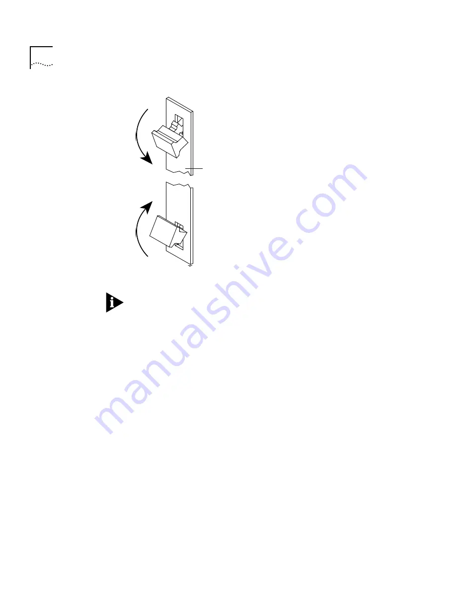
Figure 7   


Handles in Inward (Inject) Position


NOTE:


 Do not push the handles outside the center position or you will eject 

the module. These handles act as “ejectors” when pushed outward and 
“injectors” when pushed inward.


8


See the following section on “LED Activity” to verify that the TRSM has been 
properly installed. 


9


Tighten the TRSM’s securing screws using a flat-blade screwdriver.

Module faceplate

Module faceplate

Summary of Contents for LANplex 6000

Page 1: ...TRSM module LANplex system software revision 6 0 or later must be installed CAUTION In order to run software revision 5 0 or later on the LANplex 6000 you must have the new LMM Plus installed in your system To verify if you have an LMM Plus installed check the module s ejector tab to ensure it says LMM Audience This guide is intended for trained technical personnel only Taking Inventory Your packa...

Page 2: ...ort is independently configurable to support either 4 Mbps or 16 Mbps operation TRSM Configurable Bridge Modes The TRSM is architected to support both source routed or transparent traffic types in the following modes Transparent T Source Routing SR Source Routing Transparent Bridge SRT Transparent The TRSM fully complies with the IEEE 802 1d bridging standard which means that the module Learns sou...

Page 3: ...ent SRT The Source Routing Transparent SRT operation complies with the 802 1d standard which provides bridging for both Source Routing and non Source Routing protocols It uses the Route Information Indicator to differentiate between SR and non SR packets and applies the appropriate bridging method on each packet received To configure the Bridging mode see Chapter 11 Administering the Bridge in the...

Page 4: ...lligator clip is connected to a suitable ground See Figure 3 on page 7 Keep the module in its antistatic shielded bag until you are ready to install it Do not touch the components pins leads or solder connections Always handle the module by its edges Additionally you should cover every empty slot with a blank faceplate to protect the system from dust or other foreign substances and to ensure prope...

Page 5: ...olatile data using the NV data save functionality on the system s Administration Console This information can be restored using the NV restore functionality See the LANplex 6000 Administration Console User Guide for information on saving restoring and resetting nonvolatile data Inserting and extracting a module will cause a warm system reboot To remove a module 1 Discharge yourself of static elect...

Page 6: ...stem The system will not operate if any other module is inserted into slot one Slot one of the LANplex 6004 is the bottom slot and slot one of the LANplex 6012 is the first slot on the left To install the TRSM in an empty slot in the LANplex system perform the following steps 1 Discharge yourself of static electricity by placing the ESD wrist strap on your wrist and clipping the alligator clip to ...

Page 7: ...e 4 Figure 4 Handles in Outward Position 4 Orient the TRSM to insert it into the LANplex system For a LANplex 6012 system orient the module so that its labeling is upright For a LANplex 6004 system the module s labeling should be on your left 11 12 13 14 15 16 5 6 7 8 4 6 5 4 6 5 RX TX RX TX RX TX RX A M B M 4 5 Ground symbol Mounting screw hole Module faceplate Module faceplate ...

Page 8: ...the selected slot and sliding the module until it stops The module stops sliding when the inject handles make contact with the front of the chassis Figure 5 shows a TRSM being installed in a 6012 system Figure 6 shows a TRSM being installed in a 6004 system Figure 5 Guiding an TRSM Module into a LANplex 6012 LANplex 6012 R LMM in slot 1 1 Err Run Ethernet Serial Ports A M B M 2 3 INS 4 5 Port Stat...

Page 9: ...e chassis by grabbing both ejector injector handles and simultaneously push them inward See Figure 7 If the system is not powered on once you feel a slight resistance inject the TRSM into the chassis 7 Relocate the inject handles back to their center position by gently pushing them inward See Figure 7 This locks the TRSM into the chassis The Power Unseat LED lights green when the TRSM is seated LM...

Page 10: ...sition or you will eject the module These handles act as ejectors when pushed outward and injectors when pushed inward 8 See the following section on LED Activity to verify that the TRSM has been properly installed 9 Tighten the TRSM s securing screws using a flat blade screwdriver Module faceplate Module faceplate ...

Page 11: ... indicating that the module is powered on Once you have completed the installation procedure only the green Power Unseat LED should remain lit Troubleshooting If LED activity is not normal check the troubleshooting suggestions listed below If the Power Unseat LED remains yellow the module is not fully seated in the chassis Eject and re insert the module as described in the installation procedure s...

Page 12: ... 45 connectors Figure 8 shows the front panel of the TRSM Figure 8 TRSM Option Module Ports 5 8 Ports 1 4 1 2 3 4 Pwr Unseat Err 5 6 7 8 Port Status Module status LEDs Securing screw Inject eject handle Inject eject handle Securing screw TRSM 1 2 3 5 6 7 4 8 Port Speed 2 1 Hub Port 1 2 3 5 6 7 4 8 Port status LEDs Port speed LEDs Port mode LEDs Ports 1 and 2 Station lobe switchable ports ...

Page 13: ...ckplane Err Error Yellow Indicates either that an error has occurred or that the module has failed a diagnostic procedure Port Status Port Status 1 8 Port Speed 1 8 Port Mode 1 2 Green Yellow Green Yellow Yellow Green Indicates that the associated port is active Indicates that an error condition has occurred with the associated port or that the port is disabled Indicates that the port is running a...

Page 14: ...and 2 when configured as lobes Table 2 Station Mode TRSM RJ 45 Pin Assignments Pin No Signal Description 1 Not used 2 Not used 3 TX Transmit 4 RX Receive 5 RX Receive 6 TX Transmit 7 Not used 8 Not used Table 3 Lobe Mode TRSM RJ 45 Pin Assignments Pin No Signal Description 1 Not used 2 Not used 3 RX Receive 4 TX Transmit 5 TX Transmit 6 RX Receive 7 Not used 8 Not used ...

Page 15: ...ore useful to you Please email comments about this guide to sdtechpubs_comments 3Mail 3Com com Please include the following information when commenting Document title Document part number listed on back cover of document Page number if appropriate Example LANplex 6000 Planning Your Site Part No 801 00251 000 Page 2 5 chapter 2 page 5 ...

Page 16: ...cation of such revision or change 3Com Corporation provides this documentation without warranty of any kind either implied or expressed including but not limited to the implied warranties of merchantability and fitness for a particular purpose 3Com may make improvements or changes in the product s and or the program s described in this documentation at any time 3Com and LANplex are registered trad...

Reviews: