background image

3-2

C

HAPTER

 3: M

AKING

 C

ONNECTIONS

Aggregating 
Servers 

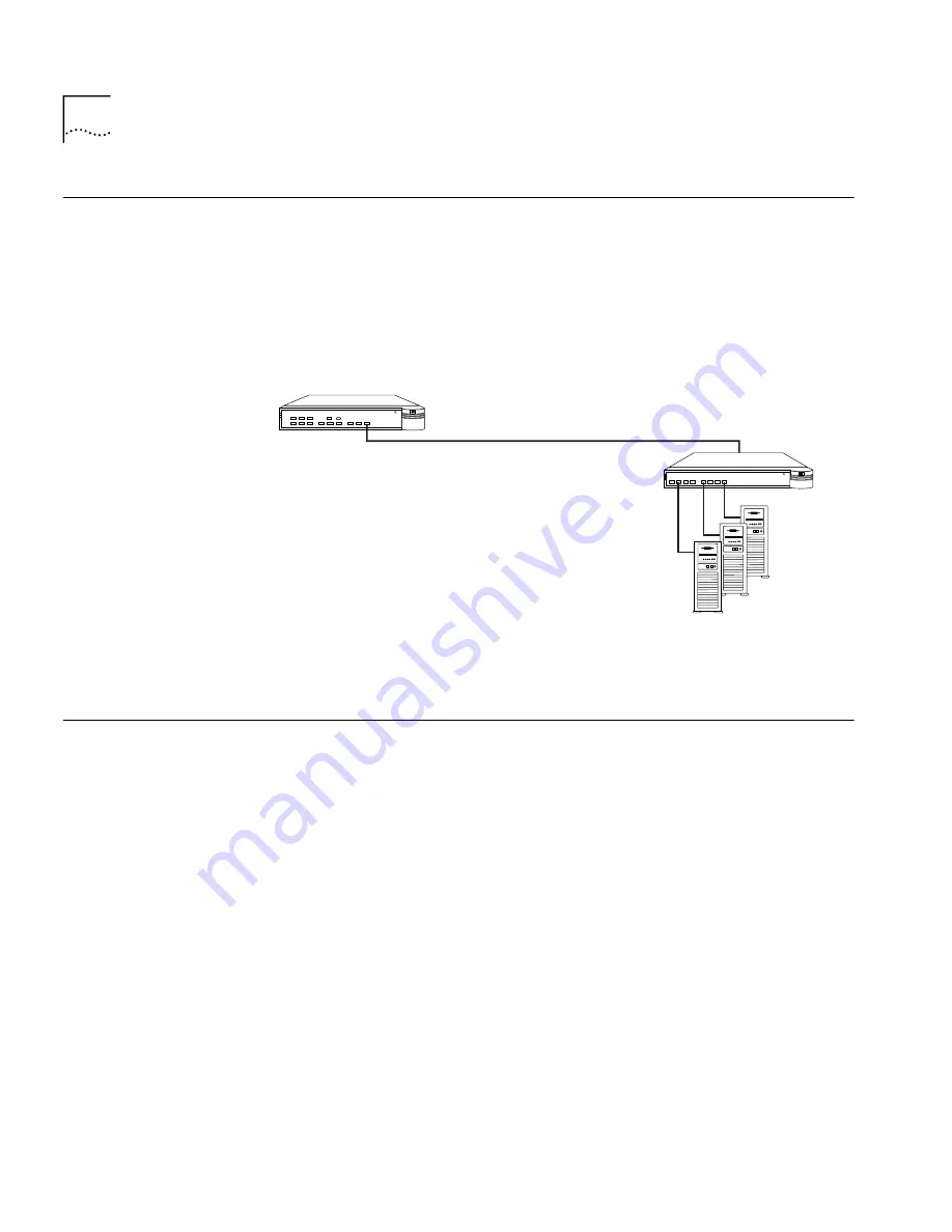
You can use the Hub 1000 SX downlinks to aggregate servers into 

server 

farms

. First, install 3Com 3C985-SX Gigabit EtherLink

®

 Server NICs in 

each server. Then, connect up to eight servers through the downlinks. 
The hub’s optional gigabit interface connector (GBIC) uplink can connect 
to a 3Com SuperStack II Switch 9300 Gigabit Ethernet switch, thereby 
connecting to the network backbone. See Figure 3-1.

Figure 3-1   

Server Farm Connection

Connecting a 
Power Workgroup

A power workgroup consists of a small number of servers, or a small 
number of sophisticated users on high-end workstations. Such a 
workgroup requires very high performance to run applications that 
move and process massive amounts of data in real time (for example, 
medical imaging, video editing, film postproduction, CAD/CAM, or 
digital prepress).

You can provide gigabit bandwidth to a power workgroup as shown in 
Figure 3-2.

®

SUPER
STACK

SuperStack II

1000 SX

SuperStack II
Hub 1000 SX

Servers with 3C985-SX

Gigabit EtherLink Server NICs

Single-mode fiber-optic cable

Maximum distance: 3 km

62.5/125 

µ

 fiber-optic cable

Maximum distance: 260 m

SuperStack II

Switch 9300

®

SUPER
STACK

SuperStack II

9300 SX

Summary of Contents for Hub 1000 SX

Page 1: ... http www 3com com SuperStack II Hub 1000 SX User Guide A member of the 3Com SuperStack II System Part No 09 1354 000 Published March 1998 ...

Page 2: ...in are provided to you subject to the following United States Government Legend All technical data and computer software is commercial in nature and developed solely at private expense Software is delivered as Commercial Computer Software as defined in DFARS 252 227 7014 June 1995 or as a commercial item as defined in FAR 2 101 a and as such is provided with only such rights as are provided in 3Co...

Page 3: ...res and Functions 1 4 2 INSTALLING THE HUB Safety Precautions 2 1 Package Contents 2 1 Hub Description 2 2 Front Panel 2 2 Rear Panel 2 3 Preparing the Site 2 3 Installing and Connecting the Hub 2 3 Mounting in a Rack 2 3 Placing on a Desktop 2 5 Interpreting Hub Indicators 2 5 Installing and Connecting a GBIC Module 2 7 Using Optional Power Systems 2 8 Advanced RPS 2 8 Power Modules 2 9 Cabling O...

Page 4: ... Power Connected A 2 With Power Disconnected A 3 POST Messages A 3 Logging On A 4 Changing the Password A 5 Configuring Port Settings A 5 Disabling Ports A 7 Disabling Auto Negotiation A 8 Configuring the Uplink for Asymmetric Flow Control A 10 Displaying Hub Status A 12 Restoring the Factory Default Settings A 14 Updating the Firmware Image A 15 Checking the Firmware Version A 15 Transferring the...

Page 5: ...ce C 1 Access by Analog Modem C 2 Access by Digital Modem C 2 3ComFacts Automated Fax Service C 2 3ComForum on CompuServe Online Service C 3 Support from Your Network Supplier C 3 Support from 3Com C 4 Returning Products for Repair C 5 GLOSSARY INDEX 3COM CORPORATION LIMITED WARRANTY FCC CLASS A VERIFICATION STATEMENT ...

Page 6: ......

Page 7: ... 2 3 Rack Mounting the Hub 2 4 2 4 Sample GBIC Module 2 7 3 1 Server Farm Connection 3 2 3 2 Power Workgroup Connection 3 3 3 3 Aggregated Switches Connection 3 4 3 4 Mixed Connection 3 5 3 5 Connection to Another Hub 1000 SX 3 5 3 6 Uplink Connection to a 10 100 Mbps Switch 3 6 A 1 Console Port A 1 ...

Page 8: ......

Page 9: ...odules 2 7 2 4 Advanced RPS Configuration Options 2 10 3 1 Gigabit Ethernet Maximum Cable Lengths 3 1 3 2 Troubleshooting Tips 3 6 A 1 Situations That Require Configuring Port Settings A 5 A 2 Port Configuration Menu A 7 A 3 Hub Status Information A 12 A 4 File Transfer Error Messages A 18 A 5 Fatal Error Messages A 18 ...

Page 10: ......

Page 11: ...is also assumed that the user has some knowledge of repeater technology If release notes are shipped with this product and the information in the release notes differs from the information in this guide follow the information in the release notes Table 1 and Table 2 list conventions that are used throughout this guide Table 1 Notice Icons Icon Notice Type Description Information note Important fea...

Page 12: ...ase letters and the appropriate value Commands are not case sensitive The words enter and type When you see the word enter in this guide you must type something and then press the Return or Enter key Do not press the Return or Enter key when an instruction simply says type Keyboard key names If you must press two or more keys simultaneously the key names are linked with a plus sign For example Pre...

Page 13: ...ning a high bandwidth application such as medical imaging video editing film postproduction CAD CAM or digital prepress The Hub 1000 SX is an eight port repeater All ports transmit and receive at a speed of one gigabit per second The hub forwards all incoming packets without filtering them to all links except the originating link thus providing a shared bandwidth domain Like a switch the Hub 1000 ...

Page 14: ... available on a link For Gigabit Ethernet devices full duplex operation allows a peak data transmission rate of 2 Gbps All Hub 1000 SX ports operate only in full duplex mode and receive frames from attached segments at a speed of 1 Gbps Each port s input buffer places received packets in an 18 KB input FIFO to wait in a queue for the hub s internal bus The hub grants ports access to the bus in a r...

Page 15: ...the core of the network when the hub is connected to the network backbone The uplink can be reconfigured for asymmetric outgoing flow control to support a connection to a server or 10 100 Mbps switch Auto Negotiation Related to flow control is the auto negotiation capability in which the Hub 1000 SX ports and linked devices advertise their flow control capabilities and automatically select the bes...

Page 16: ...re updates Power on self test POST diagnostics determine whether the hub is functioning properly at power up Frame aging firmware improves performance by minimizing unnecessary frame aging and subsequent attempts to retransmit packets at the protocol level Round robin arbitration grants fair access for all ports to the hub s internal bus on a packet by packet basis Signal retiming restores the tim...

Page 17: ... all jewelry from your hands and wrists before installing the hub Use insulated or nonconductive tools CAUTION Power for the unit must be supplied by a grounded power source The hub should never be connected to an ungrounded AC outlet or power supply Package Contents Remove the hub from the shipping package and verify that you have received these items in good condition Hub 1000 SX unit Rack mount...

Page 18: ...re equipped with Gigabit Ethernet uplink devices Indicators see Table 2 2 show hub and port status when power is on 1000BASE SX downlink ports PORT STATUS LEDs BW usage meter Hub operation LEDs GBIC port AC input DC power Console Reset Front panel Rear panel AC IN RESET CONSOLE DC POWER GBIC 1000BASE SX 1 TX RX 2 TX RX 3 TX RX 4 TX RX 5 TX RX 6 TX RX 7 TX RX 8 TX RX 1 BW USAGE 2 3 4 5 6 7 8 9 PAUS...

Page 19: ...n site meets the following conditions The hub is accessible and you can easily connect the cables The cables are away from Sources of electrical noise such as heating ventilation and air conditioning HVAC radios transmitters and broadband amplifiers Power lines and fluorescent lighting fixtures Water or moisture cannot enter the hub s case Airflow around the unit and through the vents is not restr...

Page 20: ... Rack Mounting the Hub 6 Remove the protective rubber cap from each downlink port and attach the proper cable to make the desired network connection Table 2 1 provides connector and cable information for downlink connections For guidelines on making typical connections see Chapter 3 1000BASE SX 1 TX RX 2 TX RX 3 TX RX 4 TX RX 5 TX RX 6 TX RX 7 TX RX 8 TX RX 1 BW USAGE 2 3 4 5 6 7 8 9 PAUS E RPS FA...

Page 21: ... typical connections see Chapter 3 Apply power to the hub in either of these ways Plug one end of the power cord into the AC input socket and the other end into a power source Connect the hub to a power supply as described in Using Optional Power Systems later in this chapter Interpreting Hub Indicators When power is applied all the indicators on the front panel light momentarily The UNIT STATUS L...

Page 22: ... Amber ON The internal temperature exceeds 158 F 70 C RPS ON Green ON The Advanced RPS is connected and turned on UNIT STATUS Amber ON The hub is performing POST diagnostics If the amber LED remains lit for longer than 30 seconds POST has failed or the CPU has halted Flashing An error has occurred Green ON The hub is operating normally Flashing A firmware update is proceeding Amber Green Flashing ...

Page 23: ...ices For example you can use the 1000BASE LX module to reach much greater distances than is possible with 1000BASE SX connections A sample GBIC module appears in Figure 2 4 Table 2 3 lists the types of GBIC modules available from 3Com Figure 2 4 Sample GBIC Module Table 2 3 GBIC Modules Module Type 3Com Part Number Connector Type Cable Type Maximum Cable Length Meters 1000BASE CX 3CGBIC4 3CGBIC4 6...

Page 24: ... to make the desired network connection Both ends of the connection must be of the same media type CX LX or SX 7 Reconnect power to the hub Using Optional Power Systems You can ensure fail safe operation and constant power to SuperStack II components by using the SuperStack II Advanced Redundant Power System Advanced RPS and the SuperStack II Uninterruptible Power System UPS These units and associ...

Page 25: ...Y Cable Type 2 part number 3C16079 an Advanced RPS can contain a maximum of eight 100 watt Power Modules supporting as many as four Hub 1000 SX units Using the cable supplied with the Power Module you connect the Power Module to the DC power connector located on the rear panel of the Hub 1000 SX For the DC power connector location see Figure 2 1 In the event of a failure in a Power Module an alert...

Page 26: ... power from a single Power Module instead of being powered directly from a standard AC source If the Power Module fails you can swap the faulty module for a new one This swapping method requires a reset of the hub as in a power cycle A cold Power Module supplies power after about 5 seconds Managed redundancy Connect the hub s AC power cable to a standard AC outlet Use the straight DC cable supplie...

Page 27: ...here are too many units connected to the Advanced RPS To calculate the total power consumption of all units connected to the Advanced RPS 1 Calculate the total wattage of all the units connected to the Advanced RPS For example one Hub 1000 SX has a maximum power consumption of 65 watts two Hub 1000 SX units have a maximum power consumption of 130 watts and so forth 2 Divide the total wattage of al...

Page 28: ......

Page 29: ...000 SX degrades the performance of the second hub CAUTION Connecting a Gigabit Ethernet switch downlink to a Hub 1000 SX downlink degrades the performance on the link to the switch Table 3 1 Gigabit Ethernet Maximum Cable Lengths Signal Type Laser Wavelength Connector Type Cable Type 50 125 µ Multimode Fiber 62 5 125 µ Multimode Fiber Single Mode Fiber Shielded Balanced Pair Coaxial Jumper 1000BAS...

Page 30: ...Workgroup A power workgroup consists of a small number of servers or a small number of sophisticated users on high end workstations Such a workgroup requires very high performance to run applications that move and process massive amounts of data in real time for example medical imaging video editing film postproduction CAD CAM or digital prepress You can provide gigabit bandwidth to a power workgr...

Page 31: ...tall 3C16925 uplink devices in the SuperStack II Switch 1000 or SuperStack II Switch 3000 switches Then connect up to eight switches to the Hub 1000 SX through the eight downlinks The hub s optional GBIC uplink can connect to a 3Com SuperStack II Switch 9300 Gigabit Ethernet switch thereby connecting to the network backbone See Figure 3 3 The Hub 1000 SX does not support bandwidth aggregation trun...

Page 32: ...Switch 1000 with 3C16925 uplink device SuperStack II Hub 1000 SX 10 100 Mbps UTP links Maximum distance 100 m SUPER STACK SuperStack II 3900 Multiple 10 Mbps clients SUPER STACK SuperStack II 1000 SX Multiple 10 100 Mbps clients Single mode fiber optic cable Maximum distance 3 km 62 5 125 µ fiber optic cable Maximum distance 260 m SuperStack II Switch 9300 SuperStack II Switch 3900 SUPER STACK Sup...

Page 33: ...cable Maximum distance 3 km 62 5 125 µ fiber optic cable Maximum distance 260 m SuperStack II Switch 9300 SUPER STACK SuperStack II 9300 SX SUPER STACK SuperStack II 1000 SX Servers with 3C985 SX Gigabit EtherLink Server NICs SuperStack II Switch 1000 with 3C16925 uplink device 10 100 Mbps UTP links Maximum distance 100 m SUPER STACK SuperStack II 3900 Multiple 10 Mbps clients SUPER STACK SuperSta...

Page 34: ... Gigabit Ethernet standards or does not support auto negotiation Or the link may be physically damaged for example the cable may be damaged Disable auto negotiation on the port see Appendix A Configure the other end of the link for forced configuration see the configuration guidelines for the device on the other end of the link A restored connection rules out physical damage ACTIVITY LED does not ...

Page 35: ...ub status Update the firmware image The console port a DB 9 standard male connector is located on the Hub 1000 SX rear panel See Figure A 1 Figure A 1 Console Port The console port default settings are 9600 baud 8 data bits 1 stop bit No parity Auto baud and modem connections are not supported Console AC IN RESET CONSOLE DC POWER GBIC 3Com Corporation Santa Clara CA Made in USA REFER TO INSTRUCTIO...

Page 36: ...However if you do disconnect the power you can watch POST messages when you reconnect the power With Power Connected To connect the console port while the hub is connected to power 1 Connect a null modem cable between the PC serial port and the console port on the hub s rear panel See Figure A 1 2 Turn on the PC 3 Start the terminal emulation program 4 Configure the program with the same settings ...

Page 37: ...ply The PC screen displays POST messages followed by the CLI header and the password prompt POST Messages When you connect the hub to power or when you press the Reset button on the hub s rear panel the PC screen displays messages while POST is proceeding When POST is finished the CLI header appears followed by the password prompt For example POST Level 0 PASS Checking FDS valid Performing Level 1...

Page 38: ...et at the factory is admin If this is the first time that anyone has logged on to the hub enter the default password at the prompt admin Asterisks instead of plain text appear at the prompt while you are typing the password The Hub 1000 SX Configuration menu appears Hub 1000 Configuration Menu 1 Configure port settings 2 Display hub status 3 Update firmware image 4 Change password 5 Logout Enter c...

Page 39: ...password Password changed The following sections show examples of how to use the Hub 1000 SX Configuration menu Configuring Port Settings Table A 1 summarizes the situations that require you to configure port settings through the Port Configuration menu Table A 1 Situations That Require Configuring Port Settings Situation Action You do not want a port to be connected Disable the port A port cannot...

Page 40: ... and 7 Hub 1000 Configuration Menu 1 Configure port settings 2 Display hub status 3 Update firmware image 4 Change password 5 Logout Enter choice 1 Enter port number s from 1 to 9 3 5 7 The Port Configuration menu appears and the specified ports are displayed For example Port Configuration Menu 1 Enable port 2 Disable port 3 Enable Auto Negotiation 4 Disable Auto Negotiation Force link 5 Show port...

Page 41: ...le port Disable the port for linking 3 Enable auto negotiation Enable auto negotiation The factory default is auto negotiation enabled on all ports 4 Disable auto negotiation force link Disable auto negotiation 5 Show port settings List the current settings for all ports 6 Use factory default settings Return selected ports to factory default settings 7 Save new port settings Save the settings Sele...

Page 42: ... settings without specifying that they persist after a hub reset If you want settings to persist select option 7 before selecting option 9 Disabling Auto Negotiation Disabling the auto negotiation capability enables forced link on a port When forced link is enabled linked devices must have matching flow control capabilities For example a port that is set for forced link and outgoing flow control c...

Page 43: ...it Selected ports 1 Enter choice 4 Enable Outgoing Flowcontrol Y N y Port 1 is a downlink Because downlinks support outgoing flow control only you can enable or disable outgoing flow control but you cannot configure incoming flow control You might choose to disable outgoing flow control if the port is linking to a device that does not support flow control Port Configuration Menu 1 Enable port 2 Di...

Page 44: ...gure the uplink for asymmetric flow control to connect it to a server or 10 100 Mbps switch The server or switch must have the appropriate NIC or uplink device support flow control and be configured to receive pause frames The following example shows how to configure the uplink for asymmetric flow control by disabling auto negotiation enabling outgoing flow control and disabling incoming flow cont...

Page 45: ... port 3 Enable Auto Negotiation 4 Disable Auto Negotiation Force link 5 Show port settings 6 Use factory default settings 7 Save new port settings 8 Exit without change to settings 9 Apply changes and exit Selected ports 9 Enter choice 7 Settings saved Because option 7 has been selected the settings will persist after a hub reset Port Configuration Menu 1 Enable port 2 Disable port 3 Enable Auto N...

Page 46: ...l Y The port signals outgoing flow control capability n The port does not signal outgoing flow control capability Advertise incoming flow control Y The port signals incoming flow control capability n The port does not signal incoming flow control capability The port does not support incoming flow control Enable outgoing flow control Y or n If auto negotiation is enabled the result of the negotiati...

Page 47: ...ngs 2 Display hub status 3 Update firmware image 4 Change password 5 Logout Enter choice 2 Hub Status Port Number 1 2 3 4 5 6 7 8 9 Port is Enabled Y Y n Y n n n Y Y Link state is up Y Y n Y n n n Y Y Auto Negotiate link configuration n Y Y Y Y Y Y Y n Advertise outgoing flow control Y Y Y Y Y Y Y Y Y Advertise incoming flow control n Enable outgoing flow control Y Y Y Y Y Y Y Y Y Enable incoming ...

Page 48: ...ple Hub 1000 Configuration Menu 1 Configure port settings 2 Display hub status 3 Update firmware image 4 Change password 5 Logout Enter choice 1 Enter port number s from 1 to 9 1 9 Port Configuration Menu 1 Enable port 2 Disable port 3 Enable Auto Negotiation 4 Disable Auto Negotiation Force link 5 Show port settings 6 Use factory default settings 7 Save new port settings 8 Exit without change to ...

Page 49: ...are occasions you may need to update the hub s firmware image to install a bug fix or a standards update Firmware updates are made available on the 3Com World Wide Web site http www 3com com Checking the Firmware Version To verify that the firmware version on the 3Com World Wide Web site is more recent than the version installed on the hub display the hub status At the Hub 1000 SX Configuration me...

Page 50: ... 1000 SX Configuration menu prompt enter 3 Hub 1000 Configuration Menu 1 Configure port settings 2 Display hub status 3 Update firmware image 4 Change password 5 Logout Enter choice 3 The hub enters file transfer mode and prompts you to begin the file transfer Please initiate XMODEM transfer now Press ESC to abort C The C character indicates that the hub is waiting for the terminal emulation progr...

Page 51: ...nsfer without requiring you to log in again To restart the file transfer repeat steps 6 and 7 Logging Off To log off the CLI at the Hub 1000 SX Configuration menu prompt enter 5 Hub 1000 Configuration Menu 1 Configure port settings 2 Display hub status 3 Update firmware image 4 Change password 5 Logout Enter choice 5 The screen returns to the CLI header and the password prompt Troubleshooting If a...

Page 52: ...Xmodem error Timed out sending ACK The hub could not send an acknowledgment Xmodem error Timed out waiting for packet The time limit for receiving a packet was exceeded Timed out waiting for transfer to start The time limit for starting the file transfer was exceeded Xmodem error Got too many errors to continue The hub error limit was exceeded Xmodem error A general protocol error occurred Abort k...

Page 53: ... to 95 relative humidity noncondensing Electrostatic discharge Does not exceed 25 kV Operating altitude 300 to 3000 meters 296 to 9840 ft AC input voltage 90 264 V 115 230 V nominal Input frequency range 47 63 Hz single phase AC Inrush current 40 A peak maximum at cold start for half cycle at any rated input voltage no damage to the supply from repeated on off on cycles under hot or cold condition...

Page 54: ......

Page 55: ...n Board Service 3ComBBS 3ComFactsSM automated fax service 3ComForum on CompuServe online service World Wide Web Site Access the latest networking information on 3Com Corporation s World Wide Web site by entering our URL into your Internet browser http www 3com com This service features the latest information about 3Com solutions and technologies customer service and support news about the company ...

Page 56: ...ructions on 3Com products 24 hours a day 7 days a week Call 3ComFacts using your Touch Tone telephone using one of these international access numbers Country Data Rate Telephone Number Australia up to 14400 bps 61 2 9955 2073 Brazil up to 14400 bps 55 11 5181 9666 France up to 14400 bps 33 1 6986 6954 Germany up to 28800 bps 4989 62732 188 Hong Kong up to 14400 bps 852 2537 5601 Italy up to 14400 ...

Page 57: ...alified to provide a variety of services including network planning installation hardware maintenance application training and support services When you contact your network supplier for assistance have the following information ready A list of system hardware and software including revision levels Diagnostic error messages Details about recent configuration changes if applicable If you are unable...

Page 58: ...Com Canada Calgary Edmonton Montreal Ottawa Toronto Vancouver 403 265 3266 403 423 3266 514 683 3266 613 566 7055 416 498 3266 604 434 3266 3Com France 33 1 69 86 68 00 3Com GmbH Czech Republic Slovak Republic 420 2 21845 800 3Com GmbH cont d Germany Central European HQ Hungary Poland 49 30 34 98790 Berlin 49 89 627320 Munich 36 1 250 83 41 48 22 6451351 3Com Iberia Portugal Spain 351 1 3404505 34...

Page 59: ...er Products sent to 3Com without RMA numbers will be returned to the sender unopened at the sender s expense To obtain an RMA number call or fax Country Telephone Number Fax Number U S A and Canada 1 800 876 3266 option 2 408 764 7120 Latin America 1 408 326 2927 408 764 7120 Europe South Africa and Middle East 44 1442 435860 44 1442 435822 Elsewhere 1 408 326 2926 1 408 764 7120 ...

Page 60: ......

Page 61: ...rk over long laser wavelength 1300 nm multimode fiber MMF or single mode fiber SMF cable 1000BASE SX The IEEE 802 3 physical layer specification for a 1000 Mbps Ethernet network over short laser wavelength 850 nm MMF or SMF cable Advanced RPS 3Com SuperStack II Advanced Redundant Power System asymmetric flow control A relationship between linked network devices in which only one of the devices can...

Page 62: ... cable sheath The glass center supports the transmission of light signals flow control A method for ensuring that a transmitting entity does not overwhelm a receiving entity with data See also asymmetric flow control incoming flow control outgoing flow control pause frame symmetric flow control forced link A method by which devices link with fixed and matching signaling capabilities See also auto ...

Page 63: ... send pause frames See Asymmetric flow control partition A repeater function that isolates a particular port from the network because of an excessive number of collisions Once the problem causing the collisions is corrected the port is reactivated pause frame A set of bits that tells a transmitting device to stop the transmission of data frames for a specified period or to resume the transmission ...

Page 64: ...nvironments including Ethernet token ring FDDI SNA and ATM symmetric flow control A relationship between linked network devices in which both devices can send and receive pause frames Also called bidirectional flow control See also asymmetric flow control flow control pause frame twisted pair Wiring similar to that found in the telephone system consisting of two insulated wires loosely twisted aro...

Page 65: ...idth aggregation 3 3 bidirectional flow control 1 3 bulletin board service C 1 C cables 2 5 2 7 2 9 3 1 calculating power consumption for Advanced RPS 2 11 carrier integrity monitor 1 4 command line interface CLI A 1 CompuServe C 3 configuration 1 1 A 1 auto negotiation 1 3 forced link A 8 configuring port settings A 5 connections console port A 2 downlink 2 5 guidelines 3 1 power workgroup 3 2 up...

Page 66: ...rack mounting 2 3 rear panel 2 3 status A 12 A 13 hub operation LEDs 2 6 I IEEE specifications 802 3x 1 2 802 3z 1 4 incoming flow control 1 2 indicators at power on 2 5 descriptions 2 6 installation GBIC module 2 8 hub desktop placement 2 5 hub rack mounting 2 3 J jabber control 1 4 L LED descriptions 2 6 indicators 1 4 LINK LED 2 6 M managed redundancy for Advanced RPS 2 10 maximum cable length ...

Page 67: ...on 2 3 specifications B 1 environmental operating ranges B 1 physical dimensions B 1 power requirements B 1 standard usage for Advanced RPS 2 10 status hub A 13 SuperStack II Advanced Redundant Power System RPS 1 1 2 8 Advanced RPS Power Module 2 9 Hub 1000 SX See hub Switch 1000 3 3 Switch 3000 3 3 Switch 3900 3 3 Switch 9300 3 2 3 3 3 5 Uninterruptible Power System UPS 1 1 2 8 2 10 switches aggr...

Page 68: ......

Page 69: ...als 3Com makes no warranty or representation that its software products will work in combination with any hardware or applications software products provided by third parties that the operation of the software products will be uninterrupted or error free or that all defects in the software products will be corrected For any third party products listed in the 3Com software product documentation or ...

Page 70: ... consequential damages for certain products supplied to consumers or the limitation of liability for personal injury so the above limitations and exclusions may be limited in their application to you This warranty gives you specific legal rights which may vary depending on local law 3Com Corporation 5400 Bayfront Plaza Santa Clara CA 95052 8145 408 764 5000 FCC CLASS A VERIFICATION STATEMENT WARNI...

Reviews: