


7-Slot Chassis Fan Tray Removal and Replacement Guide
5
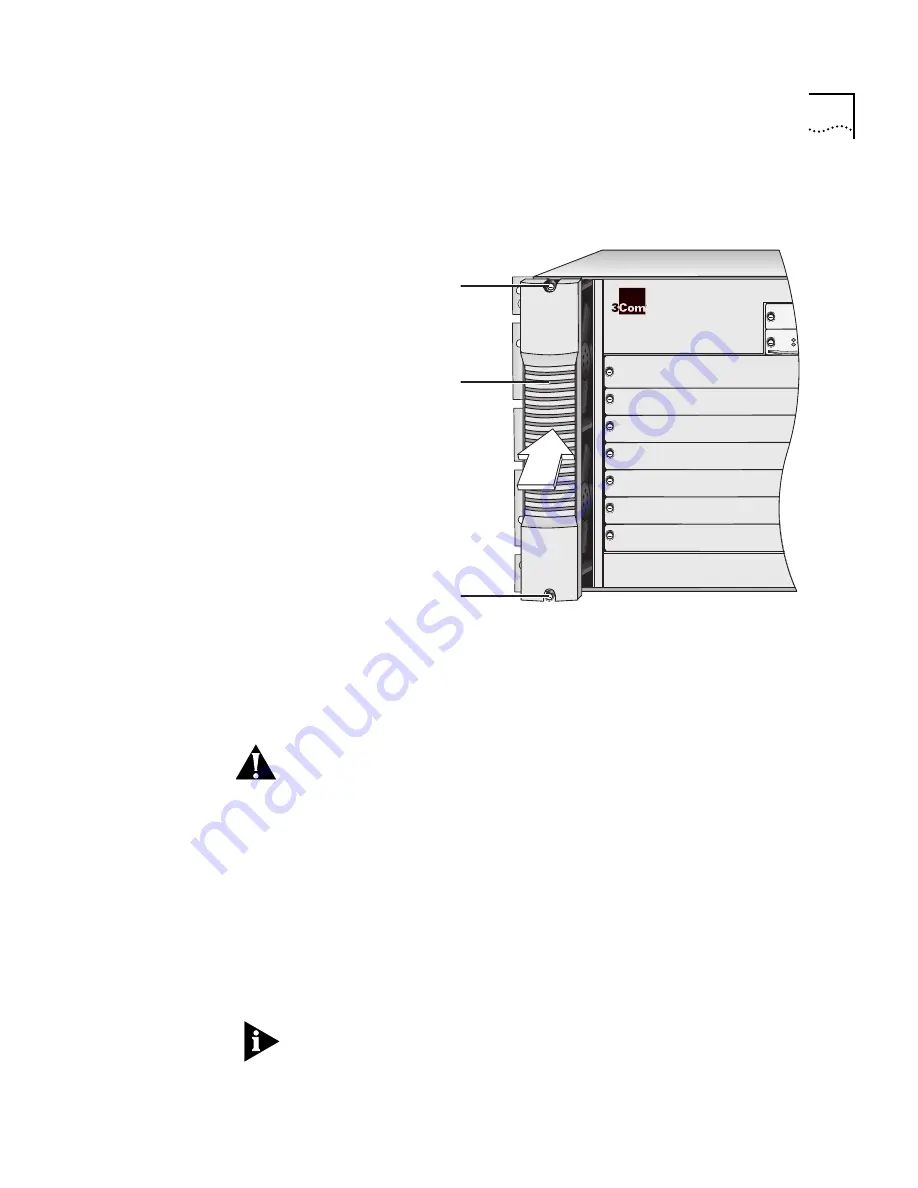
Figure 5
Installing the Fan Tray into the Chassis Using the Handle
4
Align the fan tray connector (Figure 4) and the backplane connector.
5
Gently push the fan tray inward until the connectors engage.
You feel a slight resistance as the connectors engage.
CAUTION:
If the resistance is too great, the fan tray connector and
backplane connector may not be aligned properly. Do not force the fan
tray inward or you can damage the connectors. If necessary, remove
and reinsert the fan tray, ensuring that the connectors are properly
aligned.
6
Verify that the fan tray is flush with the front of the chassis. If the fan
tray and the chassis are not aligned, remove the fan tray and reseat it.
7
Secure the fan tray to the chassis by tightening the two spring-loaded
screws (Figure 5) using a flat-blade screwdriver. Tighten the
spring-loaded screws to a Torque Specification of from 5 to
7 inch-pounds.
To ensure that you tighten screws to Torque Specification, use a torque
screwdriver.
R
1
2
3
4
5
6
7
8
9
Spring-loaded
screw
Spring-loaded
screw
Fan tray
handle


