Inserting an SFP Transceiver
To be recognized as valid, the SFP transceiver must have the
following characteristics:
1000BASE-SX or 1000BASE-LX media type:
■
1000BASE-SX SFP transceiver – Use this transceiver to
connect the Switch directly to a multimode fiber-optic
cable.
■
1000BASE-LX SFP transceiver – Use this transceiver to con-
nect the Switch directly to a single-mode fiber-optic cable
or to a multimode fiber using a conditioned launch cable.
If the SFP transceiver is faulty, it will not operate within
the Switch. See “Troubleshooting“ on page 6.
Use of non-3Com SFPs is not recommended. If the SFP
transceiver is invalid, it will not be recognized by the
Switch.
Use the following sequence of steps to activate the SFP ports:
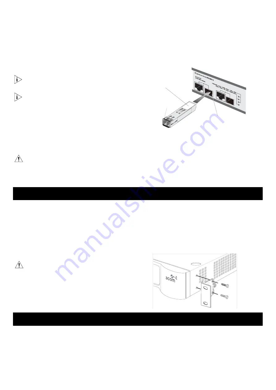
1
Hold the transceiver so that the fiber connector is toward you
and the product label is visible, as shown in Figure 2. Ensure
the wire release lever is closed (in the upright position).
2
Gently slide the transceiver into the SFP slot until it snaps into
place.
CAUTION:
SFP
transceivers are keyed and can be
properly inserted only one way. If the transceiver does not
snap in when you insert it, remove it, turn it over, and
then reinsert it.
3
Remove the plastic protective cover if fitted.
4
Connect the fiber cable.
5
Attach a male duplex LC connector on the network cable into
the duplex LC connector on the transceiver. The transceiver
connects to the network using a duplex LC connector.
6
Connect the other end of the cable to a device fitted with an
appropriate Gigabit Ethernet connection.
7
Check the Module Active LEDs on the front panel of the
Switch to ensure that it is operating correctly.
Figure 2
Activating an SFP Port
Removing an SFP Transceiver
To remove the transceiver (it is not necessary to power off your
Switch):
1
Disconnect the cable from the transceiver.
2
Move the wire release lever downwards until it is pointing
toward you.
3
Pull the wire release lever toward you to release the catch
mechanism; the transceiver will then easily slide out.
Introduction
The Switch is supplied with two mounting brackets and four
screws. These are used for rack-mounting the unit. When
mounting the unit, you should take note of the guidelines given
in
.
Rack-Mounting the Unit
The Switch is 1U (1.75 in.) high and will fit in a standard 19-inch
rack.
CAUTION:
Disconnect all cables from the unit before
continuing. Remove the self-adhesive pads from the
underside of unit, if already fitted.
1
Place the unit the right way up on a hard, flat surface with
the front facing towards you.
2
Locate a mounting bracket over the mounting holes on one
side of the unit.
3
Insert the two screws supplied in the mounting kit and fully
tighten with a suitable screwdriver.
4
Repeat the two previous steps for the other side of the unit.
5
Insert the unit into the 19-inch rack and secure with suitable
screws (not provided).
6
Reconnect all cables.
Figure 3
Inserting the Screws
Refer to the information about LEDs given earlier in this guide to
see if the problem can be identified and rectified. Here are some
common problems that can occur.
A link is already connected, but the Link/Activity Status LED
for the port is off
There is a problem with this connection. Verify that:
The connected device is powered on and operating correctly.
The cable is connected at both ends.
The cable is not damaged.
If the connection is to a workstation, that the workstation's
network interface card is installed and configured correctly.
The correct category of cable is being used for the required
link speed. Category 3 cables can be used for 10BASE-T
operation only. Category 5 cables are required for
!
Product
label
Suitable slot
n host Switch
o
Wire release
lever
M
OUNTING
K
IT
I
NSTRUCTIONS
T
ROUBLESHOOTING
6


