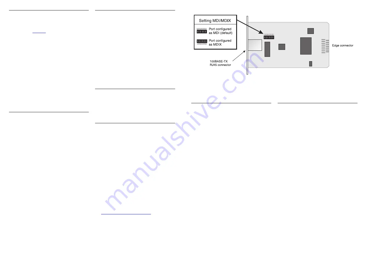
Setting the MDI/MDIX Link
The 100BASE-TX Transceiver Module has a
movable link for configuring the port as MDI
or MDIX; see
Figure 1
. The Module is supplied
with the link set to MDI.
The general rule for setting the link is:
■
Set to MDI — for connecting the Module
port to an MDIX port on another hub or
switch, using a ‘straight through’ cable.
■
Set to MDIX (cross-over) — for connecting
the Module port to an endstation or server,
using a ‘straight through’ cable.
To move the link, ensure you are wearing an
anti-static wristband connected to a suitable
earth point. Hold the edges of the Module’s
board and pull the link firmly away from the
board. Replace the link in the correct position.
Installing the Module into a Unit
1
Ensure that the unit is disconnected from
the mains power supply, and you are
wearing an anti-static wristband
connected to a suitable earth point.
2
Place the unit on a flat surface. Using a
suitable screwdriver, remove the blanking
plate from the rear of the unit to reveal
the slot for the Module. Do not remove
any other screws from the rear of the
unit. Refer to the user guide supplied with
the unit if uncertain of the position of the
blanking plate.
3
Keep the blanking plate in a safe place.
If you remove the Module at any time,
you must replace the blanking plate to
prevent dust and debris entering the unit
and to aid the circulation of cooling air.
4
Hold the Module so that the text on the
front panel is upright, and slide it into the
unit, ensuring the edge connector is fully
engaged. The front panel of the Module
should lie flush against the rear panel of
the unit. Fix the front panel of the Module
to the unit, using the two screws from the
blanking plate.
Connecting and Powering Up
1
Insert the RJ45 connector on your cable
into the socket on the Module. Connect
the other end of the cable to an
appropriate device with a 100Mbps Fast
Ethernet 100BASE-TX twisted pair
interface. The 100BASE-TX port supports
Category 5 cable over a maximum length
of 100m (328ft).
2
Power up the unit.
3
Check the LEDs on the front of the unit to
ensure that the Module is operating
correctly.
LEDs
LEDs on the unit indicate the Module status.
Refer to the user guide that accompanies the
unit for a description of the LED behavior.
Problem Solving
If you suspect a problem, carry out the
following checks before contacting your
supplier:
■
Ensure the unit in which the Module is
fitted is powered up.
■
Ensure the Module is correctly installed.
■
Ensure that the device at the far end of the
segment is powered up and operating
correctly.
■
Ensure that the cable and connectors are
free from damage and that the RJ45
connector at each end of the cable is
correctly engaged in its appropriate socket.
■
Check that the MDI/MDIX setting is
correct for your configuration. See
“Setting the MDI/MDIX Link”
, above.
Technical Specification
Operating temperature: 0–50°C (32–122°F)
Humidity: 0–95% non-condensing
Power consumption: 3W maximum
Standards:
Functional
ISO/IEC 8802-3
IEEE 802.3u
Safety
UL 1950
EN 60950
CSA 22.2 #950
Environmental
EN 60068
EMC
EN55022 Class B*
FCC Part 15 Class A
CSA M108.8 Class A
EN50082-1
AS/NZS 3548 Class B*
VCCI Class 2*
* Category 5 screened cables must be used
to ensure compliance with the Class B /
Class 2 requirements of this standard. The
use of Category 5 unscreened cables
complies with the Class A / Class 1
requirements.
Electromagnetic Compatibility
FCC Statement
This equipment has been tested with a Class A
computing device and has been found to
comply with part 15 of FCC Rules. Operation
in a residential area may cause unacceptable
interference to radio and TV receptions
requiring the operator to take whatever steps
are necessary to correct the interference.
CSA Statement
This Class A digital apparatus meets all
requirements of the Canadian
Interference-causing Equipment Regulations.
Cet appareil numérique de la classe A respecte
toutes les exigences du Règlement sur le
matériel brouilleur du Canada.
Figure 1
100BASE-TX Transceiver Module


