


TC-SPLIT USER MANUAL
6
3C Concept S.A.S
6
TC-SPLIT_MANUEL_EN_105.DOCX
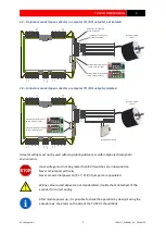
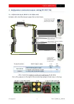
4 - Configuration and module outputs cabling (P5 P6 P7 P8)
4.1
–
Differentials outputs (RS422 or HTL differential)
Examples with and without power supply from external device
A
B
Z
A
Z
B
0V
_EX
T
+V
_EX
T
1
A
B
Z
A
Z
B
0V
_EX
T
+V
_EX
T
1
A
B
Z
A
Z
B
0
V
_
E
X
T
+
V
_E
X
T
1
A
B
Z
A
Z
B
0V_EXT
+V_EXT
1
A
B
Z
A
Z
B
0V_EXT
+V_EXT
1
+10/30V
1
0V
SLAVE
External power from VFD: NO jumpers,
Output are isolated
Variable-frequency drive(VFD)
with differentials inputs and
power output (5 to 30Vdc)
Internal power: SET Jumpers as decribed,
Output are not isolated
5V Outputs
24V Outputs
Optional 0V wire
Variable-frequency
drive(VFD) with
differentials inputs but
no power output
24V
5V
24V
5V
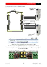
Outputs isolation
Kind of power supply
1-2
(right)
2-3
(left)
Not isolated
5Vd
c
Internal power supply
YES
-
10-30Vdc Internal power supply
-
YES
Isolated
5
-30Vdc
External power supply
-
-
« YES »: mean that 2 Jumpers must be set superimposed horizontally
Pin 1 of the jumpers is at the right of the connector (assuming terminal screw on the top)
Jumpers on the left (10-30V)
LEDS
Jumpers on the right (5V)


