


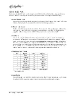


Connector Specifications
=
95
1
GPI 1
GPI 1 RTN
9
SIGNAL GND
14
10
13
GPO 6
25
GPO 5
12
GPO 4
24
GPO 3
11
GPO 2
22
INPUTS
OUTPUTS
+5V, 200mA MAX
SOURCE
GPI/O (DB25-F)
1K
INTERNAL CIRCUITS
1K
15
2
3
16
1K
4
17
1K
5
18
1K
6
19
1K
GPO 1
23
GPI 2 RTN
GPI 2
GPI 3 RTN
GPI 3
GPI 4 RTN
GPI 4
GPI 5 RTN
GPI 5
GPI 6 RTN
GPI 6
21
8
Figure 30: GPI Connection Schematic
Summary of Contents for V2000 Series
Page 1: ...O P E R A T I O N S manual I M A G E S E R V E R 2 0 0 0 Model V2000...
Page 10: ...4 Image Server 2000...
Page 50: ...44 Image Server 2000...
Page 56: ...50 Image Server 2000...