background image

24

25

2VV.

 Creating innovative solutions for you and your business since 1995.
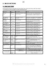
8. MALFUNCTIONS

8.1 MALFUNCTIONS

Disconnect the main power supply before any intervention to the unit. If you are not sure of the correct steps, 
do not attempt to perform any repairs and call a professional service!

Description

Unit 

behaviour

Likely problem

Solution

44 – Fan 

error

Unit 

out of order

Overheated fan or defect on thermal 

contact of inlet fan

Determine the cause of the overheating (defective 

bearing, short-circuit...) or replace the motor. Check the 

thermal contacts from the motor to the regulator.

45 – Mandatory 

maintenance/filter 

clogged

Unit 

operational

Filter clogged or the time to 

maintenance

Replace filters. After replacing or device maintenance, do 

not forget to reset the MENU 1616 – FILTER TIMER

46 – Heater 

malfunction

Unit 

out of order

Heater malfunction

Check the heater and the condition of the safety 

thermostat Does the heater have proper cooling?

Check engine running.

47 - malfunction in 

external temperature 

sensor (45,46)

Unit 

out of order

Temperature sensor malfunction on 

terminals 45,46

Check that the sensor is correctly connected to the 

electronics or test it measuring its resistance (the 

resistance value at +20°C is around 10k

W

)

48 – Outlet temperature 

sensor malfunction 

(49,50)

Unit 

out of order

Temperature sensor malfunction on 

terminals 49,50

Check that the sensor is correctly connected to the 

electronics or test it measuring its resistance (the 

resistance value at +20°C is around 10k

W

)

49 – Inlet temperature 

sensor malfunction 

(51,52)

Unit 

out of order

Temperature sensor malfunction on 

terminals 51,52

Check that the sensor is correctly connected to the 

electronics or test it measuring its resistance (the 

resistance value at +20°C is around 10k

W

)

60 – Exchanger’s 

return sensor 

malfunction (53,54)

Unit 

out of order

Temperature sensor malfunction on 

terminals 53,54

Check that the sensor is correctly connected to the 

electronics or test it measuring its resistance (the 

resistance value at +20°C is around 10k

W

)

61 – Room temperature 

sensor malfunction 

(55,56)

Unit 

out of order

Temperature sensor malfunction on 

terminals 55,56

Check that the sensor is correctly connected to the 

electronics or test it measuring its resistance (the 

resistance value at +20°C is around 10k

W

)

62 - malfunction in 

external temperature 

sensor from BMS

Limited 

operation of 

the device

Temperature sensor malfunction in 

BMS

Check that in the BMS that the address where the 

sensors sends the data is properly set 

(on the right regulator) Check the function of the sensor 

in the BMS

63 - malfunction in room 

temperature sensor 

from BMS

Limited 

operation of 

the device

Temperature sensor malfunction in 

BMS

Check that in the BMS that the address where the 

sensors sends the data is properly set 

(on the right regulator) Check the function of the sensor 

in the BMS

79 – Heating reduced 

due to low air flow

Unit 

operational

Only information

The air flow settings were reduced, limiting the heater 

output to prevent overheating

65 – Communication 

error

Unit out of 

order

Communication error

Check the communication cable for damages and if it 

is properly connected Observe the wiring diagram to 

prevent occurrences that may disrupt communication 

(wiring near high tension, phenomena on site causing 

disruptions)

Unit’s not working

Unit 

out of order

Power supply interrupted

Check that the power supply is not interrupted

Blown fuse

Check the fuse in side the control module

The heating switches 

off automatically

Unit 

operational 

but not 

heating

The heater overheats

The heater overheats due to insufficient air flow. Check 

that the ventilators are in good order and that the air 

supply is not disrupted.

Summary of Contents for IC3-CONTROL

Page 1: ...IC3 CONTROL EN INSTALLATION AND OPERATION MANUAL ver 1 11 12 2019...

Page 2: ...installing the regulator read carefully the entire manual The manufacturer reserves the right to make changes including in the technical documentation without prior notice Keep the manual in a safe pl...

Page 3: ...re in good order Contact the supplier in case of any doubt Do not attempt to commission a damaged product If the product is not unpacked upon delivery it must be sto red in a dry room with a temperatu...

Page 4: ...since 1995 3 MAIN PARTS Regulator lid Cable glands Connector terminal block Control electronics Grounding bridge PE Null bridge N Source AC module Regulator IC3 AC Regulator IC3 EC Regulator lid Cabl...

Page 5: ...RDUBICE 002 N ZEV SLO 2 602 S06285 PROM T N KRESLIL M TKO 1 2 HMOTNOST IST TOLEROV N P ESNOST DATUM D VOD ZM NY N ZEV MATERI LU David pr chal 16 3 2016 Josef ezn ek A 14 3 2016 ISO 2768 mK OE M AC5 3...

Page 6: ...ze tor mus b t instalov n tak aby mohl okolo proudit a nedoch zelo k jeho p eh v n te minim ln doporu en odstupov vzd lenosti tor i d lkov ovlada musej b t instalov ny tak m byl dostate n p stup v p p...

Page 7: ...supply the switching components and accessories must be connected according the wiring diagram The connected fans must not exceed the rated current of the unit Alterations of the internal wiring of t...

Page 8: ...pump 13 14 Door contact 15 16 Room thermostat 17 18 External control NIGHT REDUCTION 63 25 A A B B GND GND 66 66 64 26 20 20 L in L in L out L out 63 CANH A CANL GND 12V B A B 12V GND 646566 2 1 2 1...

Page 9: ...C3 S AC 7 9 24 23 22 11 8 10 8 Door contact 5 6 Room thermostat 17 18 External control 2 1 2 1 Recommended Alarm Heater wiring Safety Thermostat overheat Thermostat overheat Thermostat L N A B B A GND...

Page 10: ...TACHO RPM MOTOR 1 TACHO RPM MOTOR 2 TACHO RPM MOTOR 3 TACHO RPM MOTOR 4 TACHO RPM MOTOR 5 TACHO RPM MOTOR 6 TACHO RPM MOTOR 7 TACHO RPM MOTOR 8 TACHO RPM MOTOR 9 TACHO RPM MOTOR 10 Heater control DIG...

Page 11: ...OR 3 TACHO RPM MOTOR 4 TACHO RPM MOTOR 5 TACHO RPM MOTOR 6 TACHO RPM MOTOR 7 TACHO RPM MOTOR 8 TACHO RPM MOTOR 9 TACHO RPM MOTOR 10 IC3 S EC 1 2 3 2 3 Recommended Alarm Heater wiring Safety Thermostat...

Page 12: ...x 150m MASTER SLAVE no 1 The total bus length of all chained air curtains must not exceed 150m CHAINING SLAVE no 2 SLAVE no 10 SLAVE SLAVE MASTER A A A A A B B B B B GND GND GND GND GND SLA VE no 1 1...

Page 13: ...ories START UP After connecting power supply the display lights up and the data is loaded The device is ready to be activated once the service data has fully loaded The remote control has a touch scre...

Page 14: ...ings with closed doors Air flow settings with closed doors Language Display backlight Parameters Date and time App Back to previous screen Confirm return Confirm return Display required air flow 20 st...

Page 15: ...NUAL Required heating rate in manual mode CANCEL Confirm return Confirm return Back to main screen Back to main screen Confirmation of selection Tap on a day to set different time modes Tap to add a n...

Page 16: ...be entered manually or by using a QR code for quick pairing of the unit Pairing smart device 1 Pairing using QR code IC3 gate 1 After scanning QR code from the controller press Save for saving the un...

Page 17: ...in this guide Ad 3 Thermostat NO NC Ad 4 Number of connected EC motors on regulator 0 10pcs Don t forget to connect the speed outputs of the motors to the appropriate connectors on the panel of the re...

Page 18: ...urrent timer status Setting the desired time until an alert appears on the main screen of the display 1000h 5000h Sample display of status of fouled filter on main screen RESET button use after replac...

Page 19: ...not be taken into account End of winter period month number Start of winter period month number Enable disable function Temperature limit the heating is disabled if the temperature on the Outdoor sens...

Page 20: ...nual mode The menu is enabled only in units with water exchanger MENU WATER ANTIFREEZE Settings 20 100 Ventilation rate with open doors 20 100 MENU SUBUNITS Use this menu to set the behaviour of the I...

Page 21: ...ax Maximum temperature for return water Setting periods for blower movement Only at 0 00 time and in Standby mode Minimum water flow can be set only for analog control of blower MENU Adv WATER SETTING...

Page 22: ...ET Use this to reset the default values Press FACTORY RESET to reset the default values of MENU 1616 Once completed we recommend to turn the main supply off and on Electric connection Option 2 CP 1 CP...

Page 23: ...C is around 10kW 60 Exchanger s return sensor malfunction 53 54 Unit out of order Temperature sensor malfunction on terminals 53 54 Check that the sensor is correctly connected to the electronics or...

Page 24: ...d in the list available at the supplier s Give the following information to the supplier or service type designation of the air curtain accessories in use place of installation serial number condition...

Page 25: ...your business since 1995 Ozna en Popis 1 Transformer 4A 7A 16A 2 Power supply 3 PCB modul A 4 PCB modul AC 5 Box 6 Rel SSR only 16A type Ozna en Popis 1 Power 2 PCB modul A 3 PCB modul TACHO 4 Box IC3...

Page 26: ...LAVE GND Firma 2VV slo 2 602 S09232 Kreslil Moj Verze 3 GND Datum 6 11 2018 NOT USED SSR AC16 GND N zev IC2 C AC5 16 Verze 3 5 PE 3 100 125 150 170 190 230 2 80 zdroj 12V N L 0 TRAFO 16A 1 4 CANL CANH...

Page 27: ...ASTER zdroj 24V N L 24V GND Firma 2VV slo 2 602 S09234 Kreslil Moj Datum 06 11 2018 Verze 3 0 10V N zev IC2 S AC5 16 EV 5 PE 3 100 125 150 170 190 230 2 80 0 TRAFO 16A 1 4 N 3 4 5 6 7 8 9 10 11 12 2 1...

Page 28: ...0 L v1 zdroj 24V N L GND 24V NTC 10K NTC 10K NTC 10K IC3 EC C IC3 EC S 11 WIRING DIAGRAM N zev IC2 EC C EV zdroj 12V N L FUSE ROOM WAT ROOM OUTSIDE EC FAN CONTROL PANEL N DC12V PE RPM GND PWM RELAY NO...

Page 29: ...your business since 1995 12 CONCLUSION 12 CONCLUSION In case of any doubt or query do not hesitate to contact our sales or technical support departments CONTACT Address 2VV s r o F blovka 568 533 52 P...

Reviews: