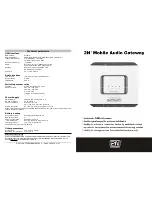
2N® Mobile Audio Gateway
Basic Functions
·
The
2N
®
Mobile
Audio
Gateway
(hereinafter MAG) is designed to
automatically answer a call from the
GSM mobile network and transfer the
caller’s voice to audio output. It is
designed to be connected to the input of
a PA exchange or similar device
intended for voice reproduction.
·
The device is equipped with a switching
contact relay for activation of the
exchange during an ongoing call.
2N® Mobile Audio Gateway Installation and Connection
·
Proper location
Install MAG with respect to a good mobile
network signal strength.
Place MAG out of range of sensitive
devices
and
human
bodies
for
electromagnetic interference reasons.
MAG is designed for indoor use. Do not
place it near heat sources and on direct
solar radiation. It may not be exposed to
rain, flowing water and moisture,
aggressive gas, solvents etc.
·
External Antenna Connection
Screw the antenna cord into the SMA
antenna
connector.
Tighten
the
antenna connector gently with your
hand, never use a wrench!
·
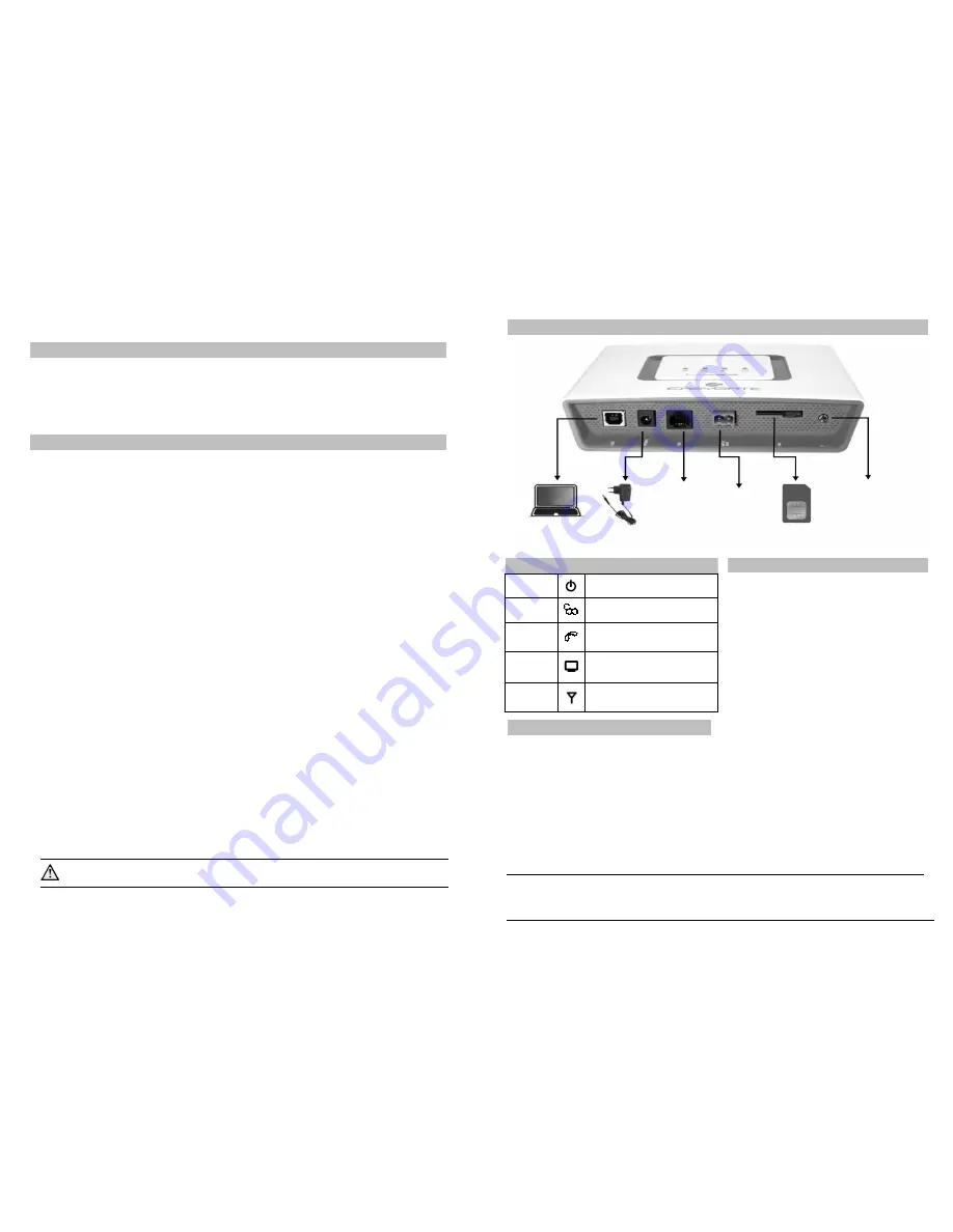
SIM card Installation
Slot for SIM card is placed on the
connector panel. Make sure your SIM
card is not PIN protected. Insert the
SIM card to the slot according to the
picture. If you wish to use PIN
protection, enter the PIN code into
MAG before the SIM is inserted. Use
the configuration tool.
·
Connection of audio input to MAG
Audio signal output runs to a 3.5mm
mono jack on the side of the antenna
connector. You can use the supplied
cable, fitted with jacks on both ends, to
connect the input connector of the
connected device. If the connected
device is fitted with a different type of
input connector, it is necessary to fit it
with a suitable adaptor or other cable.
·
Connection of switching relay
To activate the connected device, you
can use a switching contact relay run
to a connector; the mate of this
connector is supplied with the device.
The relay is closed during an ongoing
connection to the GSM network. The
relay is used for signaling, and cannot
be used for switching mains voltage!
(see technical parameters)
·
Battery installation
Insert four pieces of rechargeable
battery NiMh size AA into the covered
compartment on the back side of the
gateway. Refer to the symbols in the
battery space for proper battery
placement and polarity. Use mentioned
type of batteries only!
Mains Supply Connection
MAG is 12V DC voltage powered.
Connect the attached power adapter
(12V/1A DC) to the power supply
connector. After connection, switch on
MAG with the power switch on the right
hand side of connector panel.
·
MAG configuration
It is not necessary to configure the
device for basic MAG operation.
Configuration is necessary if a PIN code
is used to protect the SIM card, or if
you need to define the numbers from
which it is possible to control the MAG
and so on.
Do not activate the power supply until the antenna is connected to
EasyGate to avoid the GSM module damage.
2N® Mobile Audio Gateway Connection Layout
Use of the device
·
When there is an incoming call, MAG
automatically picks up the call and
connects the audio output with the
incoming GSM voice channel.
·
It also closes relay contacts connected to
the relay connector. This enables
activation of the connected audio device
and reproduction of the caller’s voice.
·
The state of the ongoing call is signalled
by the LED Audio connection.
·
At the end of the call by the caller, the
MAG goes into standby mode.
Configuration via USB
·
The device is fully functional in the
default configuration. If you don’t need a
special setting, it is not necessary to
configure the device.
·
For configuration by PC, you must install
the PCManager UNI program. Connect
the MAG by USB cable to the PC.
·
After connection, a virtual series port is
created (USB serial port, FTDI) through
which the PCManager connects to the
gateway.
·
When setting up PCManager, it is
necessary to select the number of the
virtual series port.
·
Using PCManager, you can:
- Enter the PIN of the SIM card used
(protection)
- Permit calls from selected numbers only
(GSM routing table)
- Configure output volume (telephone line)
- Configure parameters of GSM connection,
especially roaming (GSM&SIM)
- Upgrade firmware - only with special FW
for MAG!
Other
parameters
configurable
via
PCManager are intended for the GSM
gateway. Do not change their setting.
Be careful when setting up roaming, which is permitted in the factory setting,
and if the gateway operates in this mode, incoming calls will be billed at the
relevant tariff!
Indication LEDs
Power
supply
Blue light
– mains supply
Yellow light
– battery supply
GSM
Network
Blue flashes
– logged out
Blue light
– logged in
Audio
connection
No light
– standby
Yellow light
– call in progress
PC
connection
Green light
– PC connection active
During configuration by USB
interface
Signal
strength
Signal strength indication
Four levels of signal displayed
Power
adapter
Relay
contact
Not used
SIM
Switch
ON/OFF
PC (USB)


