

INSTALL INSTRUCTIONS
The
2GIG
‐
DBELL1
‐
345
is
a
dual
purpose
doorbell
that
will
work
with
both
the
standard
24V
wiring
in
the
house
and
wirelessly
with
the
2GIG
Control
Panel.
It
features
a
button
that
is
fully
water
‐
resistant
and
remains
illuminated
when
the
24V
house
doorbell
wiring
is
used.
Box Contents
•
2
wood
screws
•
2
machine
screws
•
Doorbell
sensor
•
Install
Instructions
•
O
‐
ring
Programming
The
following
steps
describe
general
guidelines
for
programming
(learning)
the
sensor
(2GIG
‐
DBELL1
‐
345)
into
the
2GIG
panel.
Scroll
between
op ons
using
the
←
and
→
arrows.
Move
to
the
previous
or
next
prompt
by
pressing
the
↑
and
↓
arrows.
1
Select
RF
sensor
#
(01
to
48).
Assign
the
Doorbell
to
a
new
zone.
2
Select
RF
sensor
type.
(23)
no
response
type
(system
will
chime
when
the
doorbell
is
pressed,
but
not
trigger
alarm)
3
Select
RF
equipment
type.
(1)
contact
4
Select
RF
sensor
equipment
code.
Enter
1063
for
the
DBELL1
‐
345
2GIG
doorbell.
5
Enter
RF
sensor
serial
number
(7
digits).
Manual
Entry:
Type
in
the
last
7
digits
of
the
TX
ID
that
is
found
outside
of
the
box
or
on
the
back
of
the
device.
Auto
Entry:
With
the
panel
in
Learn
‐
in
mode
(press
Shift
then
Learn)
press
the
doorbell
button.
The
correct
TX
ID
should
appear.
Accept
the
correct
TX
ID
by
pressing
ok
.
Remember to press the
↓
arrow to con nue going through the 2GIG system con
fi
gura on prompts.
6
Select
RF
sensor
equipment
age
(0
to
1).
(0)
new
(product
is
new)
(1)
existing
(product
already
exists)
7
Select
RF
sensor
1
loop
number
(1
to
3).
(1)
1
8
Select
RF
sensor
1
dialer
delay.
(0)
disabled
9
Construct
RF
sensor
voice
descriptor.
Press
Insert
then
press
any
number
between
002
and
255
to
add
a
word.
For
example,
if
you
wanted
to
name
this
doorbell
as
“front
door,”
press
Insert
then
press
098
for
FRONT
.
Press
Insert
then
press
058
for
DOOR
.
Press
↓
to
con nue
con
fi
guring
the
system.
10
Select
RF
sensor
reports
(0
to
1).
(0)
disabled
(1)
enabled
11
Select
RF
sensor
supervised
(0
to
1).
(0)
disabled
(sensor
does
not
report
loss
of
supervision)
(1)
enabled
(sensor
reports
loss
of
supervision)
12
Select
RF
sensor
chime
(0
to
13).
(0)
disabled
(panel
will
NOT
chime
when
sensor
is
activated)
(1
‐
13)
enabled
(selects
a
voice
and
chime
to
sound
when
sensor
is
activated)
13
To
program
another
sensor
click
next
.
14
To
exit
programming,
click
skip
then
end
and
exit
.
Upon
exit,
the
panel
takes
a
several
seconds
to
reboot.
Testing
Before
mounting
the
sensor,
ensure
that
the
sensor
mounting
location
provides
good
RF
communication
to
the
panel.
To
verify,
do
the
following:
1
From
the
Installer
Toolbox
,
select
walk
test
.
2
Press
and
release
the
doorbell
button
and
listen
for
chime
or
keypad
beeps
to
determine
the
appropriate
response
(refer
to
the
2GIG
Control Panel Install Guide
).
3
Exit
the
Installer
Toolbox
.
4
(Optional
after
Installing
and
Mounting)
Verify
that
the
household
24V
AC
connection
is
working
by
pressing
the
doorbell
button
to
ring
the
doorbell.
Installing and Mounting
If
possible,
locate
sensors
within
100
ft
(30m)
of
the
panel.
While
a
transmitter
may
have
a
range
of
350
ft
(106
m)
or
more
out
in
the
open,
the
environment
at
the
installation
site
can
have
a
significant
effect
on
transmitter
range.
Although
the
doorbell
has
been
designed
to
withstand
weather,
avoid
mounting
it
in
areas
where
it
will
be
exposed
to
extreme
moisture.
1
To
remove
the
sensor
cover,
use
your
finger
to
press
the
tab.
This
disengages
the
clip
holding
the
cover
to
the
base.
2
(Optional)
Pull
the
existing
house
24
AC
wiring
through
the
hole
if
connecting
the
doorbell
to
existing
24V
doorbell
wiring.
3
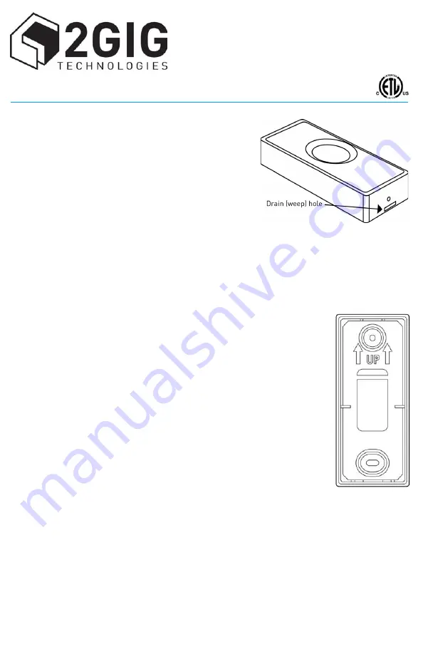
Mount
the
2GIG
‐
DBELL1
‐
345
using
the
orientation
shown.
Use
the
supplied
Phillips
wood
screws
to
attach
the
base
to
the
mounting
surface.
Ensure
that
the
orientation
arrows
are
pointed
up
(as
shown).
4
Place
the
supplied
O
‐
ring
around
the
perimeter
of
the
base.
5
If
available,
attach
the
existing
24V
AC
household
doorbell
wiring
to
the
board
using
the
machine
screws
provided.
If
this
step
is
skipped,
the
doorbell
will
work
only
with
the
2GIG
Control
Panel
and
the
LED
will
not
illuminate.
6
Pull
the
battery
tab
out
and
discard
tab
properly.
7
Replace
the
sensor
cover.
Ensure
that
the
drain
hole
is
facing
down.
If
the
cover
does
not
snap
in
place,
it
may
be
upside
down.
FCC
ID:
WDQ
‐
DBELL1345
Industry
Canada
ID:
7794A
‐
DBELL
1345
DOORBELL


