2easy DMR21/D16 Technical Manual Download Page 4

2 EASY

ELECTRIC LOCK CONNECTION

SPECIFICATION

S

1) Door Lock Controlled with Internal Power

1. The door lock is limited to 12Vdc, and holding current must be less 
than 250mA when using internal power supply mode

2. The Unlock Mode Parameter must be set to 0 

(

default).

3.  Jumper  set  to  1-2  position  for  power-off-to-unlock  safety 
type(

Normally closed mode

); set to 2-3 position for power-on-to 

-unlock type(

Normally open mode

 ).

4. If different unlocking time is needed to be configured, change the 

unlock time on door station,detail

ed

 information refer to DT system 

technical guide 

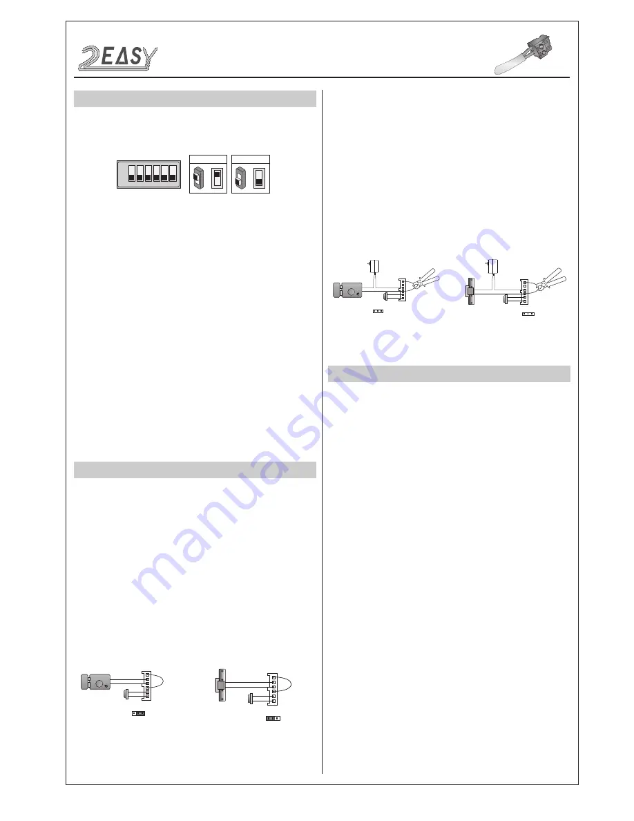
2) Door Lock Controlled with External Power

1. The external power supply must be used according to the lock

2. The jumper must be taken off before connecting

3. Setup the 

Unlock Mode Parameter

 for different lock types

• 

 Power-on-to-

U

nlock type:Unlock Mode=0(default)

• 

 Power-off-to-

U

nlock type:Unlock Mode=1

4. If different unlocking time is needed to be configured, change the 

unlock time on door station,more detail information refer to DT system 
technical guide

JP_LK

12V 300mA

Exit button

Jumper position in 2-3 

+

-

+12V
LK - 
LK+
N.O.
EB-
EB+

1 2 3

Power-on-to-Unlock type:

Power-on-to-Unlock type:

12V 300mA

Jumper position in 1-2 

+12V
LK - 
LK+
N.O.
EB-
EB+

+

-

JP_LK

1 2 3

Exit button

Power-off-to-Unlock type:

Power-off-to-Unlock type:

+

+

-

-

+12V
LK - (GND)
LK+(COM)
N.O.
EB-
EB+

Take off the Jumper

JP_LK

Cut off the line 

1 2 3

Exit button

+12V
LK - (GND)
LK+(COM)
N.O.
EB-
EB+

Take off the Jumper

+

+

-

-

JP_LK

Cut off the line 

1 2 3

Exit button

• 

Power:  

26Vdc(supplied by PC6)

• 

Power Consumption: 

1W standby, 5W working

• 

Unlock Power output: 

12Vdc,250mA

• 

Unlock tim

e

:  

1~99s

• 

Working temperature: 

- 20ºC ~ +55ºC

• 

Dimension

s

316(H)x133(W)x48(D)mm 

 INSTALLATION GUIDE

DIP SWITCHES SETTING

Totally 6 bits can be configured by dip-switch. The switches can be 

modified either before or after installation, but restarting the power is 

needed whenever the switches have been modified

Bit-1 and Bit 2 is for door station ID settings. When multi door stations 

are installed in the system, these two bit must be set correctly, the 

first door station set to 00, the second one set to 01, the third one set 

to 10, the fourth one set to 11. If only one door station is installed, set 

to 00.

Bit-3 is for single or double row button door station selection. If the 

door station is a double row button, such as DMR21-D8, set this bit to 

0. For single row button door station,set to 1.

Bit-4 is for button code selection. if use the default codes for each 

button of the door station, set to 0. If use the programmed codes, set 

to 1.(the code for each button can be programmed by software, detail 

information refer to DT system technical guide)

Bit-5 is for unlocking time quick setting. 0 is the default setting,and the 

default time is 1 second. If set to 1,the unlock time is 5 seconds(the 

unlock time can be modified by door station or software)

Bit-6 is for activating the key A  and key B. Normally key A and key B 

is not activated(about the functions of key A and key B,please refer to 

DT system technical guide ),Just when it set to 1,the key A and key B 

is activated.

ON(1)

=

OFF(0)

=

ON

ON

ON

1 2 3 4 5 6

DMR21 Technical M

a

nu

al

-4-

Summary of Contents for DMR21/D16

Page 1: ...P21 F3 EP21 S12 DMR21 D32 F1 DMR21 D16 DMR21 S4 F1 DMR21 D8 F1 DMR21 TECHNICAL MANUAL Installation Guide 2 Modules 4 Camera Module 4 Keypad Module 6 TFT Module 11 Card Reader Module 12 Call Button Module 14 Module Connection 16 CONFIGURATIONS 19 Common Door Station Setting 19 Software Update 20 Tone Update 20 Namelist Update 21 2 wire series ...

Page 2: ...contact of the relay NO Normally open contact of the relay EB Exit button positive connection port EB Exit button negative connection port JP LK Electic lock type setting SET DIP switches for door station settings CN KMB Call button module connection port CN T COIL Reserved CN FUN Touch sensor keypad module or TFT display module connection port CN WGN Proximity reader module connection port Bus L1...

Page 3: ...2 3 4 Cut a hole and install the wall box Final result Use the screws to fasten the panel Connect and plug bus line connector with cable Standard mounting RF CARD OFF ON OFF ON DBC4A A B C D DBC4A A B C D Impedance switch Impedance switch 100 240VAC BUS IM BUS DS PC6 AC OFF ON DBC4A A B C D Impedance switch Code 29 Code 31 Code 30 Code 32 Code 5 Code 7 Code 6 Code 8 Code 1 Code 3 Code 2 Code 4 DMR...

Page 4: ... 1 2 3 Exit button 12V LK GND LK COM N O EB EB Take off the Jumper JP_LK Cut off the line 1 2 3 Exit button INSTALLATION GUIDE DIP SWITCHES SETTING Totally 6 bits can be configured by dip switch The switches can be modified either before or after installation but restarting the power is needed whenever the switches have been modified Bit 1 and Bit 2 is for door station ID settings When multi door ...

Page 5: ...le in standby 1 Press Key A the Unlock indicator turns on with the warning sound of BP BP 2 Press and hold Key B to enter the Unlocking Time Delay Setting a warning sound of BP will be heard and the Status indicator blinks one time per second The counting of Unlocking Time is the times that Status indicator blinks the units is second For example the Status indicator blinks for four times that mean...

Page 6: ...ired You should press confirm button after finish input ting the code number each time otherwise the operation will be cancelled automatically in 10s Setting items Setting range Default value Setting code Reset all settings 1 2 3 4 00 Setting the master code 1 12 digits Valid keys 0 9 1234 01 Setting the key illumination time 10 to 99 seconds continually lit 10 sec 02 Setting the unlock time 01 to...

Page 7: ...ge 01 99 3 Setting the key illumination time 4 Setting the unlock time 2 Setting the master code Default 1234 Default 10s Default 1s Inputting of new master code ex 4321 1 12 digits Input the setting code Inputting of code Input the setting code 1 Reset all settings 00 1234 4321 01 10 09 Input the setting code 02 Input the setting code 03 If the key illumination time is set to 00 the key illuminat...

Page 8: ...u set last When the operation tone is set to 0 pressing the digital keypad will sent out a sound of beep When the operation tone is set to 1 pressing the digital keypad will blink one time Cancel all the passwords except the master code Restore the master code to default value 1 2 3 4 When the item is set to 0 press the button to cancel the input and press the button to confirm the input When the ...

Page 9: ...tton Beep Beep Beep 11 SPK volume adjust setting Input the setting code Input the setting code 11 Inputting of code ex 5 range 0 9 5 Default 4 Unlock via password is still available even when the door station is talking state When door station is talking you can enter the Master code the LED turns white upon that to activate the volume adjusting function Speaker adjustment 3 up 6 down Beep Beep Be...

Page 10: ... second lock the second lock need external device to support If the password length exceeds 12 digits the system will sent out the sound of beep beep beep beep and the digitals you input before will be cleared at the same time The temporary code can not be set the same as the master code and user code The user code group1 is used to release the first lock and the user code group2 is used to releas...

Page 11: ...me list Press or to select name After that press to call the corresponding user Press Keypad Module to cancel the call This is the user interface of calling process Know that if the name list is created the resident s name will be showed on screen Press Keypad Module to cancel the call This is the user interface of conversation process The conversation time will be recorded Press Keypad Module to ...

Page 12: ...ed on TFT screen When registered ID card will be presented to a Proximity Reader Door open message will be showed on TFT Display Module screen This is the user interface of adding card please know that the user interface of delete card or initialization is similar as the following pic ture shows Master Card Setting Power on and short out EB EB a sound of BP will be sent out and the Unlock indicato...

Page 13: ... on Show the MASTER CARD ADD it will sound BP the Talk indicator and the Unlock indicator will blink and after 10 seconds it will return to standby mode i By PC ii By SD Card Delete by room number Input the room code it will sound BP and the Unlock indicator blinks one time all associated cards will be deleted Delete by User Card Show the User Cards which you need to delete It will sound BP and he...

Page 14: ...ew Mounting screw The DMR21 automatically assigns the call codes to the connected module s buttons Regardless of the structure of the call button mod ule the button numbers are listed from the top to bottom and from left to right in the case of double row buttons In the case of double row buttons Examples 01 02 03 04 05 06 07 08 RF CARD 01 02 03 04 05 06 07 08 09 10 11 12 13 14 15 16 09 10 11 12 1...

Page 15: ...8 10 12 14 16 10 12 14 16 18 20 22 24 26 28 30 32 RF CARD RF CARD 01 02 03 04 01 02 03 04 01 02 03 04 05 06 07 08 05 06 07 08 09 10 11 12 13 14 15 16 1 2 3 4 5 6 ON 01 02 03 04 05 06 07 08 NO Functions Call apartment 01 Call apartment 02 Call apartment 03 Call apartment 04 Call apartment 05 Call apartment 06 Call apartment 08 Call apartment 07 DMR21 Technical Manual 15 ...

Page 16: ...switches for system configurations Connect to CN FUN of video entry module Connect to CN KMB of video entry module Connect to CN WGN of video entry module For electronic lock safety type setting Connect to next keypad or TFT module Connect to next call button module Connect to next call button module Connect to next call button module Call button module connection port Reserved Non polarity bus li...

Page 17: ... D16 DMR21 T4 D8 DMR21 ID S4 DMR21 ID KP INPUT INPUT OUTPUT OUTPUT CN KMB RF CARD OUTPUT INPUT INPUT CN KMB CN WGN INPUT OUTPUT INPUT CN KMB CN FUN OUTPUT INPUT CN WGN RF CARD A 1 2 3 4 5 6 0 7 8 9 B OUTPUT INPUT CN FUN DMR21 Technical Manual 17 ...

Page 18: ...A 1 2 3 4 5 6 0 7 8 9 B INPUT INPUT OUTPUT OUTPUT OUTPUT INPUT OUTPUT INPUT OUTPUT INPUT CN KMB CN FUN CN WGN RF CARD OUTPUT INPUT INPUT OUTPUT INPUT OUTPUT INPUT OUTPUT INPUT OUTPUT CN KMB CN WGN MODULE CONNECTION DMR21 Technical Manual 18 ...

Page 19: ...u want to call 001 Alan_1 08 00 01 Press the first button it would call the monitor 01 in BDU 1 and it is displayed Alan_1 on TFT module This section is reserved For more details please refer to the following section of Namelist Update By SD Card Description Definition Calling By Buttons Calling By Namelist Calling By Keypad Module Press the call button to call corresponding monitors i Press touch...

Page 20: ... Insert SD card to slot iii A long warning sound of BP will be sent out and the Talk indi cator is turned on iii A long warning sound of BP will be sent out and the Status indicator is turned on iii After 3 seconds all the indicators are turned on iiii After 20 seconds a long sound of BP will be sent out and all indicators are turned off It means Software update is finished iiii After 20 seconds a...

Page 21: ...switch to ON as the following picture shows ii Insert SD card to slot DIP6 ON 1 2 3 4 5 6 ON INPUT CN KMB CN WGN iii A long warning sound of BP will be sent out and the Talk indi cator is turned on iiii After 20 seconds a long sound of BP will be sent out and the Talk indicator is turned off It means Namelist update is finished CONFIGURATIONS DMR21 Technical Manual 21 ...

Reviews: