background image

User Guide for 4 axis TB6560 driver board 


Product Features: 

  Toshiba TB6560AHQ chip - High power, maximum 3.5A drive current chipset ! 

  1-1/16 microstep setting - Higher accuracy and smoother operation than standard 1, 1/2 step!   

  Adjustable 1.5A-3A drive current settings for each axis - 25%,50%,75%,100% of full current can be set for 

different stepper motors   

  Overload, over-current and over-temperature safety - Full protection for your computer and peripheral 

equipment !   

  On board current switching - Power output can be set according to specific user requirement !   

  Full closed-type optical isolation to protect the user's computer and equipment   

  Relay spindle interface - Outputs Max. 36V 7.5A for spindle motors or coolant pump (only one device can be 

powered by this output!)   

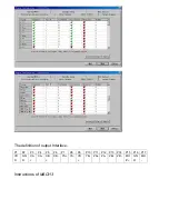
  4 channel inputs interface- Can be used for XYZ limit and emergency stop !   

  Professional design - Two stage signal processing with super anti-jamming !   

  Bipolar constant current chopper drive with non-resonant region - Controls motors smoothly through range 

without creep effect !   

  Four control inputs (divided into pairs of knives) - Allows setting of limit and emergency stop !   

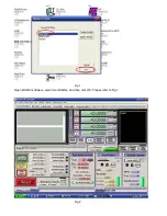
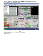
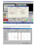
  Universal architecture - Supports most parallel software MACH3,KCAM4 etc!   
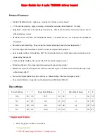
Dip settings: 

Current Setting 

1 

2 

Decay Mode Settings 

3 

4 

MicroStep Settings 

5 

6 

100% 

ON ON 

FAST 

ON ON 

ON ON 

75% 

ON OFF 

25% 

ON OFF 

1/2 ON 

OFF 

50% OFF 

ON 

50% 

OFF 

ON 1/8 OFF 

ON 

25% OFF 

OFF 

SLOW 

OFF  OFF 

1/16 OFF  OFF 

* Important Notes: 

  Power supply DC 12-36V 

(not included)   

*Voltage Selection: 


12-16V DC power supply for Nema 17 stepper motors   

Summary of Contents for 3 axis TB6560

Page 1: ... Max 36V 7 5A for spindle motors or coolant pump only one device can be powered by this output 4 channel inputs interface Can be used for XYZ limit and emergency stop Professional design Two stage signal processing with super anti jamming Bipolar constant current chopper drive with non resonant region Controls motors smoothly through range without creep effect Four control inputs divided into pair...

Page 2: ... 3 3A Nema 23 stepper motors theoretically 24V 11A DC power supply is recommended but higher power such as 24V 15A also will be good If you are not sure about the selection of power supply please feel free to contact us for help The power output of 12V shall be applied to the radiator fan of 12V Driver output compatible with 2 or 4 phase 4 6 or 8 lead stepper motors 3A max Suitable for unipolar or...

Page 3: ... Manual Interface P1 P2 P3 P4 P5 P6 P7 P8 P9 P10 P11 P12 P13 P14 P15 Z C Empty C Step Z Step X Dir X Empty Y Empty Y Dir Z Dir C Dir Spindle motor Y Step X Step STOP GND 5V vdd The definition of DB9 4 channel inputs interface P1 P2 P3 P4 P5 P6 P7 P8 P9 X Limit Y Limit Z Limit STOP Empty GND GND GND GND P10 P11 P12 P13 Input 1 Input 2 Input 3 Input 4 5 Corresponding P10 Corresponding P11 Correspond...

Page 4: ...Limit setting FOR REFERENCE ONLY Note you can also have other settings for other applications ...

Page 5: ...The definition of output Interface P1 P2 P3 P4 P5 P6 P7 P8 P9 P10 P11 P12 P13 P14 P15 P16 P17 VD D GN D XA XA XB XB YA YA YB YB ZA ZA ZB ZB MO V GN D MO Instructions of MACH3 ...

Page 6: ...Fig 1 Open MACH3 software select mach3MILL and then click OK Please refer to Fig 1 Fig 2 ...

Page 7: ...MACH3 is displayed as Fig 2 The frequently used action buttons are listed on the interface We can configure MACH software at first Fig 3 Click PORT PIN sub menu of config menu Please refer to Fig 3 Please refer to Fig 4 ...

Page 8: ...basic frequency within the above Circle 1 This parameter will affect the rotational speed of the motor After the setup of basic frequency select Circle 2 where Configuration Scripting will be defined please refer to Fig 5 ...

Page 9: ...allel Interface which is detailed in the above circle Fig 6 Then select the output signals column as shown in Fig 6 and set up the corresponding items per the setup described in the circle Fig 7 After all have been set up open the G CODE that needs to run as shown in Fig 7 ...

Page 10: ...Fig 8 Fig 9 After G CODE has been opened you may see the red button RESET flashing Click RESET to stop ...

Page 11: ...software settings according to the Fig 5 and Fig 6 Please conform the parallel cable has been pluged tightly Please turn off the power supply before changing dip settings Please use stable high quality DC power supply for this driver Problems in Mach3 using Please refer to the Mach 3 User Manual If problem persist please feel free to contact us ...

Reviews: