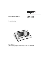
background image

INSTRUCTION MANUAL

System Controller

VSP-9000

About this manual

• Before installing and using this unit, please read this manual carefully. Be sure to keep it handy for 

later reference.

• This manual gives basic connections and operating instructions.

Summary of Contents for VSP-9000

Page 1: ...stem Controller VSP 9000 About this manual Before installing and using this unit please read this manual carefully Be sure to keep it handy for later reference This manual gives basic connections and operating instructions ...

Page 2: ...er and menu display setup BUZZER DISPLAY 53 b Joystick Setup JOYSTICK 54 b Touch screen adjustment TOUCH SCREEN SETTING 55 b Touch Screen Initialization and Reset 56 b Touch screen test TOUCH TEST 57 Software Configuration 59 b Operating Environment 59 Connection and Software Installation 60 b Install the Software 60 b Making Connections 60 System Setup Setup 61 A General General Settings 62 B Cam...

Page 3: ...uit different from that to which the receiver is connected Consult the dealer or an experienced radio TV technician for help For the customers in Canada SERVICE This unit is a precision instruments and if treated with care will provide years of satisfactory performance However in the event of a problem the owner is advised not to attempt to make repairs or open the cabinet Servicing should always ...

Page 4: ...contact the installer or location of purchase Continued use can cause fires electric shock and unit breakdowns b b b b Do not use during thunderstorms Do not use this during thunderstorms In particular never touch the AC adapter or connection cables This can cause electric shock b b b b Do not install in unstable location The unit may fall or topple causing injuries or unit breakdowns In the event...

Page 5: ...nd unit breakdowns In direct sunlight In extreme humidity or where humidity fluctuates wildly Where water could be splashed Near heating cooling equipment or humidifiers Where cold air from air conditioners contact the unit directly Where dust is extreme Near a spark source Near magnetic objects Near explosive materials Where subject to vibration Provided AC Adapter DANGER b b b b Only use with 10...

Page 6: ...r plug regularly and wipe off the dust and dirt adhering to the plug Never pull the power cord to unplug the power plug Always hold the power plug when unplugging Never leave the power plug plugged into the outlet while the DC plug is disconnected from the power source input terminal on this unit This can cause electric shock when touching with wet hands or when an infant places the power plug in ...

Page 7: ...used in a cold location the screen will initially appear darker than normal As the unit internal temperature rises the brightness will return to normal The display is a consumable part When the screen is darkened flickering or not displaying images the LED used in the interior illumination device has expired Replace with a new part Approximate service life About 50 000 hours with the display ON To...

Page 8: ...ent temperature changes suddenly such as when heating the room quickly Fogging does not occur while electrical current is present When fogging could occur Turn OFF the unit power and leave the unit in its installed position for one to two hours before use b b b b Caring for the Unit Unit 1 Unplug the power plug from the outlet 2 Gently wipe away any contamination using a soft cloth When heavily so...

Page 9: ...he controller Alarm reset password The password input screen is displayed when resetting after a warning appears on the menu display Setup password The password input screen is displayed when changing equipment settings Licensed Under U S Patent No 4974088 Accessories Check that all accessories are included AC adapter power cord x 3 North America 1 Europe 1 Great Britain 1 PC RS232 connection cabl...

Page 10: ...ns in the menu to display setup screens etc to access settings and operate the unit 2 Joystick This pans tilts and zooms the camera It is also used to initialize the touch screen and to exit graphics settings 3 Contrast adjustment volume This adjusts the brightness when the menu display is too dark to see 1 2 3 Front Back ...

Page 11: ...mera communication terminal TELEMETRY A B Connect a provided or separately purchased modular cable to this terminal Terminal A Connect a camera Terminal B Connect a camera 5 Video communication terminal VIDEO Connect video equipment multiplexer hard disk digital recorder etc When connecting this unit with video equipment always use the provided modular cable and communication conversion connector ...

Page 12: ... 4 5 6 7 8 0 9 D a t u m 0 0 0 0 0 0 0 0 0 0 0 0 0 0 0 A c c e p t v a l u e s M a x 0 0 1 0 0 0 0 1 0 0 M i n 0 0 0 0 1 0 0 0 0 1 esc del enter 1 2 3 4 5 6 7 8 0 9 D a t u m 0 0 0 0 0 0 0 0 0 0 0 0 0 0 0 A c c e p t v a l u e s M a x 0 0 1 0 0 0 0 1 0 0 M i n 0 0 0 0 1 0 0 0 0 1 SEARCH COPY MONITOR 2 MUX PLAY ENTER CLEAR STOP MENU TIMER EXIT OSD SEQUENCE REC STOP REC ALARM ALARM AUTOPAN AUTOFLIP ...

Page 13: ... SERVICE G E N E R A L I N F O R M A T I O N U N D E R S E L E C T I O N P r e s e n t c a m e r a 0 0 0 0 1 C a m e r a a d d r e s s 0 0 0 0 1 M o n i t o r U n i t 0 0 0 0 1 A B V l i n e V T E L E M E T R Y C o n n e c t o r A V i d e o P r o t o c o l A S A N Y O S S P B a u d r a t e A C o n n e c t o r B T e l e m e t r y P r o t o c o l B B a u d r a t e B V I D E O T y p e D V R M U X P r...

Page 14: ...RD CARD MENU RESET EJECT Modular cable Monitor RS485 A Terminal Coaxial cable Zoom camera Zoom camera Zoom camera Dome camera Conversion connector CARD CARD MENU RESET EJECT B VIDEO A B TELEMETRY Modular cable Monitor A B RS485 A Terminal Coaxial cable Zoom camera Zoom camera Zoom camera Dome camera Conversion connector CARD CARD MENU RESET EJECT VIDEO A B TELEMETRY Modular cable Monitor A B RS485...

Page 15: ...mmunication terminals TELEMETRY A B P27 CARD CARD MENU RESET EJECT B VIDEO A B TELEMETRY Modular cable Competitor camera Monitor A B RS485 A Terminal Coaxial cable Zoom camera Zoom camera Zoom camera Dome camera Conversion connector CARD CARD MENU RESET EJECT VIDEO A B TELEMETRY Modular cable Competitor camera Monitor A B RS485 A Terminal Coaxial cable Zoom camera Zoom camera Zoom camera Dome came...

Page 16: ...T MAIN A 1 IN 2 B VIDEO COM SW ON 1 2 3 4 A B TELEMETRY 12V 3 1 2 1 2 3 3 3 Dome camera sold separately Zoom camera sold separately Hard disk digital recorder with multiplexer function sold separately A B Provided communication conversion connector Monitor sold separately AC adapter provided WH B L S L O R B R B K Y L R D G R WH B L S L O R B R B K Y L R D G R Green Red A B Yellow White ...

Page 17: ...e To change the address of this unit Keyboard Add see P44 This unit has no power switch Turn power ON or OFF by plugging or unplugging the DC plug from the AC adapter When a startup password is set the password entry screen appears P51 SW ON 1 2 3 4 VSP 9000 ALARM PLAY R PLAY REC ALARM PLAY STOP PLAY SPEED REC STOP SEQ ON PAN ON TOUR ON SEQ PAN TOUR OFF ONE PUSH AF FOCUS FAR FOCUS NEAR IRIS CENTER...

Page 18: ...Displays Control Setup ACCEPTED VALUES screen For 1 CAMERAS setup see P47 7Press the button select 2 MONITOR LOCAL DVR MUX then press the button Set the connected DVR MUX 8This completes the setup Proceed to operating the hard disk digital recorder P32 or the camera P38 esc ent ent 1 V I D E O 2 T E L E M E T R Y 3 S E R I A L T E S T S C O M M U N I C A T I O N S C O M M U N I C A T I O N S ent e...

Page 19: ...ld separately Hard disk digital recorder with multiplexer function sold separately A B Provided communication conversion connectors Figure 1 Monitor sold separately AC adapter provided Provided communication conversion connectors Figure 2 WH B L S L O R B R B K Y L R D G R B A WH B L S L O R B R B K Y L R D G R WH B L S L O R B R B K Y L R D G R b Connecting communication conversion connectors Fig...

Page 20: ...1 Note To change the address of this unit Keyboard Add see P44 This unit has no power switch Turn power ON or OFF by plugging or unplugging the DC plug from the AC adapter When a startup password is set the password entry screen appears P51 SW ON 1 2 3 4 VSP 9000 ALARM PLAY R PLAY REC ALARM PLAY STOP PLAY SPEED REC STOP SEQ ON PAN ON TOUR ON SEQ PAN TOUR OFF ONE PUSH AF FOCUS FAR FOCUS NEAR IRIS C...

Page 21: ...plays Control Setup ACCEPTED VALUES screen For 1 CAMERAS setup see P47 7Press the button select 2 MONITOR LOCAL DVR MUX then press the button Set the connected DVR MUX 8This completes the setup Proceed to operating the hard disk digital recorder P32 or the camera P38 esc ent ent 1 V I D E O 2 T E L E M E T R Y 3 S E R I A L T E S T S C O M M U N I C A T I O N S C O M M U N I C A T I O N S ent esc ...

Page 22: ...R B R B K Y L R D G R WH B L S L O R B R B K Y L R D G R WH B L S L O R B R B K Y L R D G R B A Camera RS 485 MONITOR OUT MAIN A 1 IN 2 B VIDEO COM SW ON 1 2 3 4 A B TELEMETRY 12V 3 1 2 1 2 3 3 3 Dome camera sold separately Zoom camera sold separately Zoom camera sold separately Zoom camera sold separately Hard disk digital recorder with multiplexer function sold separately A B Provided communicat...

Page 23: ...e To change the address of this unit Keyboard Add see P44 This unit has no power switch Turn power ON or OFF by plugging or unplugging the DC plug from the AC adapter When a startup password is set the password entry screen appears P51 SW ON 1 2 3 4 VSP 9000 ALARM PLAY R PLAY REC ALARM PLAY STOP PLAY SPEED REC STOP SEQ ON PAN ON TOUR ON SEQ PAN TOUR OFF ONE PUSH AF FOCUS FAR FOCUS NEAR IRIS CENTER...

Page 24: ... screen For 1 CAMERAS setup see P47 7Press the button select 2 MONITOR LOCAL DVR MUX then press the button Set the connected DVR MUX 8This completes the setup Proceed to operating the hard disk digital recorder P32 or the camera P38 esc ent ent 1 V I D E O 2 T E L E M E T R Y 3 S E R I A L T E S T S C O M M U N I C A T I O N S C O M M U N I C A T I O N S ent esc 2 T E L E M E T R Y 2 T E L E M E T...

Page 25: ...ately Zoom camera sold separately Zoom camera sold separately Zoom camera sold separately Hard disk digital recorder with multiplexer function sold separately A B Provided communication conversion connectors Figure 1 Monitor sold separately Competitor camera AC adapter provided Provided communication conversion connectors Figure 2 RS 485 MONITOR OUT MAIN A 1 IN 2 B VIDEO COM SW ON 1 2 3 4 A B TELE...

Page 26: ...1 Note To change the address of this unit Keyboard Add see P44 This unit has no power switch Turn power ON or OFF by plugging or unplugging the DC plug from the AC adapter When a startup password is set the password entry screen appears P51 SW ON 1 2 3 4 VSP 9000 ALARM PLAY R PLAY REC ALARM PLAY STOP PLAY SPEED REC STOP SEQ ON PAN ON TOUR ON SEQ PAN TOUR OFF ONE PUSH AF FOCUS FAR FOCUS NEAR IRIS C...

Page 27: ... the button Displays Control Setup ACCEPTED VALUES screen For 1 CAMERAS setup see P47 7Press the button select 2 MONITOR LOCAL DVR MUX then press the button Set the connected DVR MUX 8This completes the setup Proceed to operating the hard disk digital recorder P32 or the camera P38 esc ent ent 1 V I D E O 2 T E L E M E T R Y 3 S E R I A L T E S T S C O M M U N I C A T I O N S C O M M U N I C A T I...

Page 28: ...K Y L R D G R WH B L S L O R B R B K Y L R D G R WH B L S L O R B R B K Y L R D G R B A RS 485 MONITOR OUT MAIN A 1 IN 2 B VIDEO COM SW ON 1 2 3 4 A B TELEMETRY 12V 3 1 2 1 2 3 3 3 Dome camera sold separately Zoom camera sold separately Zoom camera sold separately Zoom camera sold separately Hard disk digital recorder with multiplexer function sold separately A B Provided communication conversion ...

Page 29: ... To change the address of this unit Keyboard Add see P44 This unit has no power switch Turn power ON or OFF by plugging or unplugging the DC plug from the AC adapter When a startup password is set the password entry screen appears P51 SW ON 1 2 3 4 VSP 9000 ALARM PLAY R PLAY REC ALARM PLAY STOP PLAY SPEED REC STOP SEQ ON PAN ON TOUR ON SEQ PAN TOUR OFF ONE PUSH AF FOCUS FAR FOCUS NEAR IRIS CENTER ...

Page 30: ...Displays Control Setup ACCEPTED VALUES screen For 1 CAMERAS setup see P47 7Press the button select 2 MONITOR LOCAL DVR MUX then press the button Set the connected DVR MUX 8This completes the setup Proceed to operating the hard disk digital recorder P32 or the camera P38 esc ent ent 1 V I D E O 2 T E L E M E T R Y 3 S E R I A L T E S T S C O M M U N I C A T I O N S C O M M U N I C A T I O N S esc 2...

Page 31: ...ion line See Communications Setup 3 SERIAL TESTS in System Setup P46 b b b b Terminate settings This unit is equipped with camera A B communication terminals and a video communication terminal When performing communication operations connecting multiple models to the same loop from each communication terminal will cause the data to reflect at both ends affecting other data and preventing proper da...

Page 32: ...S L O R B R B K Y L R D G R WH B L S L O R B R B K Y L R D G R WH B L S L O R B R B K Y L R D G R WH B L S L O R B R B K Y L R D G R WH B L S L O R B R B K Y L R D G R WH B L S L O R B R B K Y L R D G R WH B L S L O R B R B K Y L R D G R WH B L S L O R B R B K Y L R D G R WH B L S L O R B R B K Y L R D G R WH B L S L O R B R B K Y L R D G R WH B L S L O R B R B K Y L R D G R WH B L S L O R B R B K...

Page 33: ...S NEAR IRIS CENTER GO TO PRESET TO SUB SCREEN SYSTEM SETUP MAP ENTER PLAY SPEED IRIS IRIS ADDRESS DVR MUX ADDRESS STILL TIMER ON OFF CLOCK ADJUST C A M 1 D V R 1 C A M 1 D V R 1 MENU SEQUENCE AUDIO MENU RESET TO 10 KEY MAIN MONITOR MON2 LOCK UNLOCK TO MAIN SCREEN ADDRESS SEARCH FR FI COPY EXIT OSD ADDRESS DVR ZOOM CHANNEL MENU CODE AWB SET AUX ON BLC ON ELS ON L L PHASE L L PHASE ELS OFF BLC OFF A...

Page 34: ...ess to record Four screen display button The main monitor displays a four pane screen Reverse playback button Playback speed down button Press this during playback This begins frame advance reverse still images Press repeatedly to decrease the frame speed Playback speed up button Press this during playback This begins frame advance forward still images Press repeatedly to increase the frame speed ...

Page 35: ...a is displayed larger The display panes differ based on the number of camera input terminals Press again to cancel b b b b Sub Screen Operation Main monitor button Press to operate the main monitor Monitor 2 button Press to operate monitor 2 Search button Press in any search operation menu whether during recording or while stopped Cursor buttons Use in place of the jog shuttle when making menu sel...

Page 36: ...RITY LOCKED is displayed on the monitor and a password is requested Enter the password Audio button This switches the audio output channel Copy button Image recorded in the normal recording area and the alarm recording area can be copied to a backup area or onto a CompactFlash card Play back the recording area to copy and pause it To return to the Main Menu press the button Screen display button P...

Page 37: ...B SET AUX ON BLC ON ELS ON L L PHASE L L PHASE ELS OFF BLC OFF AUX OFF AWB RESET PRESET MEMORY ZOOM PRESET ON ZOOM PRESET OFF NEXT BACK LOCK UNLOCK ADDRESS MUX CLOCK ADJUST C A M 1 M U X 1 C A M 1 M U X 1 CODE SEQ ON PAN ON TOUR ON SEQ PAN TOUR OFF ONE PUSH AF FOCUS FAR FOCUS NEAR IRIS CENTER GO TO PRESET TO SUB SCREEN SYSTEM SETUP MAP ENTER IRIS IRIS ADDRESS MUX DVR ADDRESS SPOT MON 1 SPOT MON 2 ...

Page 38: ...this while monitoring a single screen A 2x zoom screen appears Press again to cancel Camera sequence button This automatically switches the monitored live image Press again to cancel Video playback button Press to enter video playback mode Video playback is displayed on the monitor b b b b Sub Screen Operation Menu selection button The multiplexer menu is displayed on the monitor Next setting butt...

Page 39: ... 3 4 5 6 7 8 0 9 1 D a t u m 0 0 0 0 0 0 0 0 0 0 0 0 0 0 0 A c c e p t v a l u e s M a x 0 0 1 0 0 0 0 1 0 0 M i n 0 0 0 0 1 0 0 0 0 1 D i g i t C a m e r a n r C A M 1 D V R 1 C A M 1 D V R 1 C A M 1 D V R 1 C A M 1 D V R 1 ALARM PLAY R PLAY REC ALARM PLAY STOP PLAY SPEED REC STOP SEQ ON PAN ON TOUR ON SEQ PAN TOUR OFF ONE PUSH AF FOCUS FAR FOCUS NEAR IRIS CENTER GO TO PRESET TO SUB SCREEN SYSTEM...

Page 40: ...creen is displayed on the menu display Select the preset number and press the button To return to the previous screen press the button Turns ON other functions The ten key pad screen is displayed on the menu display Select the function number and press the button To return to the previous screen press the button SEQ ON PAN ON TOUR ON SEQ PAN TOUR OFF ONE PUSH AF FOCUS FAR FOCUS NEAR IRIS CENTER IR...

Page 41: ...etup buttons are displayed on the menu display Perform setup operations Note Using the or button during dome camera VCC 9000 operation will cancel cursor control Use the jog dial for cursor operation on this menu screen AUX OFF enter esc esc del enter 1 2 3 4 5 6 7 8 0 9 D a t u m 0 0 0 0 0 0 0 0 0 0 0 0 0 0 0 A c c e p t v a l u e s M a x 0 0 0 1 6 0 0 0 1 6 M i n 0 0 0 0 1 0 0 0 0 1 A U X D i g ...

Page 42: ... Y 3 S E R I A L T E S T S C O M M U N I C A T I O N S ALARM PLAY R PLAY REC ALARM PLAY STOP PLAY SPEED REC STOP SEQ ON PAN ON TOUR ON SEQ PAN TOUR OFF ONE PUSH AF FOCUS FAR FOCUS NEAR IRIS CENTER GO TO PRESET TO SUB SCREEN SYSTEM SETUP MAP ENTER PLAY SPEED IRIS IRIS ADDRESS DVR MUX ADDRESS STILL TIMER ON OFF CLOCK ADJUST SEARCH COPY MONITOR 2 MUX PLAY ENTER CLEAR STOP MENU TIMER EXIT OSD SEQUENCE...

Page 43: ... button The Main Menu appears 2Press the button The System screen language selection screen is displayed 3Press the button or button select a language then press the button The language on the system screen changes to the selected language 4Press the button Returns to the Sub screen SEQUENCE REC STOP REC SEARCH COPY MONITOR 2 MUX PLAY ENTER CLEAR STOP MENU TIMER EXIT OSD ALARM ALARM AUTOPAN AUTOFL...

Page 44: ...ettings do not need to be changed For communication setup for competitor video equipment see the Communications Chart P86 Type This displays the equipment DVR MUX connected to the video communication terminal Changing the type will require changing the Protocol and Baudrate as well Protocol This shows the communication protocol SANYO DVR MU used on this unit Baudrate Select the data transmissions ...

Page 45: ...he input range Returns to Communication Setup screen Restores the input number to 0 ent esc 1 V I D E O 1 V I D E O T y p e D V R M U X P r o t o c o l S A N Y O D V R M U B a u d r a t e 1 9 2 0 0 K e y b o a r d A d d 0 0 0 0 1 C O M M U N I C A T I O N S C O M M U N I C A T I O N S enter esc ent esc del enter 1 2 3 4 5 6 7 8 0 9 D a t u m 0 0 0 0 0 0 0 0 0 0 0 0 0 0 1 A c c e p t v a l u e s M ...

Page 46: ...d for A Connector the Video data transmission speed is fixed and A Baudrate cannot be set b b b b Communication setup when using competitor cameras B Connector Telemetry Operating a camera by connecting this unit to camera using modular cable B Protocol This is the communication protocol used on this unit Every time the communication protocol is changed B Baudrate is restored to the default value ...

Page 47: ...a problem is indicated repeat the test with TELEMETRY A connected to VIDEO and with TELEMETRY B connected to VIDEO The test results are displayed as follows B A The line is not functioning No transmission or reception B A Transmission is possible but no reception B A Reception is possible but no transmission B A The line has normal transmission and reception When connecting V and A or V and B this...

Page 48: ... Dvr Mux Clear button Disconnects all cameras A B line switch button Press the or button to change the button name Pressing this button switches the connection terminal for all cameras Single row switch button Press the or button to change the button name Pressing this button switches the connection terminal for each row ent 1 C A M E R A S 2 M O N I T O R L O C A L D V R M U X 3 F U N C T I O N S...

Page 49: ...ideo equipment Single row switch button Sets a row to be valid Single row invalidate button Sets a row to be invalid Individual setup button The ten video equipment units on the cursor line can be set a m individually ent esc T E L T E L 1 C A M E R A S 1 C A M E R A S 1 A A A A A A A A A A A A A A A A A A A A 1 1 2 1 A A A A A A A A A A A A A A A A A A A A 3 1 A A A A A A A A A A A A A A A A A A ...

Page 50: ...s Enables changing zoom focus and iris values for connected cameras Aux Enables Aux operation of connected cameras Wiper Washer Enables wipers and washers special functions of connected cameras MAPS environment Displays a user created map when power is turned ON Spot Skip When the MON2 video output for the hard disk digital recorder is set to camera sequence mode images from the camera being opera...

Page 51: ...ARMS RESET 3 PARAM MODIFICATION 4 GRAPH ENVIR LEVEL 1 5 GRAPH ENVIR LEVEL 2 6 GRAPH ENVIR LEVEL 3 Password required upon alarm reset Password required upon power ON Password required upon accessing setup menu Password required to enter Graphics Environment Setup Level 1 Password required to enter Graphics Environment Setup Level 2 Password required to enter Graphics Environment Setup Level 3 Write...

Page 52: ...e password again for confirmation 12345 then press the button When Password enabled is displayed the process is complete The PASSWORD screen is displayed again ent ent 1 A T S W I T C H I N G O N 2 A L A R M S R E S E T 3 P A R A M M O D I F I C A T I O N 4 G R A P H E N V I R L E V E L 1 5 G R A P H E N V I R L E V E L 2 6 G R A P H E N V I R L E V E L 3 P A S S W O R D P A S S W O R D esc ent es...

Page 53: ... 1 R e l e a s e d 2 A l l a t r i g h t 3 A l l a t l e f t 4 A l l u p 5 A l l d o w n 6 R o t a t e z o o m a t l e f t 7 R o t a t e z o o m a t r i g h t M a x C e n t M i n D D X 0 0 6 2 0 0 0 5 0 0 0 0 4 0 0 0 0 7 0 0 7 Y 0 0 6 2 0 0 0 5 0 0 0 0 4 0 0 0 0 7 0 0 7 Z 0 0 6 2 0 0 0 5 0 0 0 0 4 0 0 0 0 7 0 0 7 X 0 0 7 Y Y 0 0 7 Z Z 0 0 7 C O N F I G U R A T I O N 0 0 4 2 6 0 3 5 5 7 1 R E S T O...

Page 54: ... button on the screen is pressed Selections MAX loud MIN soft 2 Joystick Joystick Operation This setting sounds a buzzer when the joystick is moved Selections YES NO 3 Serial error Serial error detection This setting sounds a buzzer upon a serial communication error Selections YES NO ent ent esc 1 R E S T O R E B A S I S V A L U E S 1 R E S T O R E B A S I S V A L U E S C o n f i r m E N T E R C O...

Page 55: ... the far right 3 All at left Setting far left position Press the button with the joystick tipped to the far left 4 All up Setting topmost position Press the button with the joystick tipped to the topmost position 5 All down Setting bottommost position Press the button with the joystick tipped to the bottommost position 6 Rotate zoom at left Setting left zoom position Press the button with the joys...

Page 56: ...nate range 3400 3600 3Press the button The coordinates at the upper left are placed in memory and change to 4Press the button The button at the upper left moves to the lower right 5Press the center of the button to display the pressed coordinates The changes to coordinates numerical value The coordinates are fixed Setting value guideline Top line coordinate range 3400 3600 Bottom line coordinate r...

Page 57: ...e for this unit The DOWNLOAD MODE screen is displayed 4Operate the joystick as shown in the figure A reset touch message is displayed and the touch screen is initialized When the coordinates are memorized at dramatically offset positions this unit will not function Proceed to the settings in Touch Screen Initialization enter SAVE ESC ESC SAVE SAVE 0 3 5 7 2 0 0 7 3 7 SW ON 1 2 3 4 D O W N L O A D ...

Page 58: ...e the DOWNLOAD MODE screen is displayed Turn the dipswitch SW1 OFF b b b b Touch screen test TOUCH TEST 1Press the button or button to select TOUCH TEST then press the button The testing screen appears 2Press the boxes on the test screen is displayed in the pressed boxes Press all the boxes to check them 3Hold down the upper right box to return to the CONFIGURATION screen 1 2 Enter Enter ESC ESC 0...

Page 59: ...tware CONTENTS 2 2 2 2 Software Configuration 59 2 2 2 2 Connection and Software Installation 60 2 2 2 2 System Setup Setup 61 2 2 2 2 Language Setup Language 68 2 2 2 2 Graphics Environment Setup Maps 71 ...

Page 60: ...ndividual words as desired By creating the screen graphics environment as desired including the opening screen and the operation screen button placement the operation screen can be simplified or operation can be restricted depending on the usage environment b b b b Operating Environment PC equipped with a serial port OS Windows 9x 2000 XP System Setup Setup P61 Language Setup Language P68 Graphics...

Page 61: ...g Connections 3Connect the PC connection terminal COM on the rear panel of the unit to the PC serial port using the computer connection cable provided Before connecting make sure all equipment is turned off and disconnect camera communication and video communication cables 4Turn dipswitch SW1 ON 5Connect the power source to the unit and turn ON the PC DOWNLOAD MODE appears on the unit menu display...

Page 62: ... Create new system settings Open existing settings Save settings Download unit settings to this software Upload software settings to the unit Display a print preview of the settings list Print a settings list Exit the software 3 Tabs Click the tabs to switch between four operation screens General P62 These allow language selection communication setup buzzer setup and password setup Cameras P64 Set...

Page 63: ...ab 3Make the various settings P63 1 Language Select Language 2 Commnunications Communication Setup 3 Buzzer Display Buzzer and Menu Display Setup 4 Password Password Setup 4Make the various selections To make other settings switch using the tabs and continue operation To save settings in the PC on the File menu select Save When selecting Send to keyboard on the File menu the system setup content i...

Page 64: ... transmissions speed for the camera connected to camera communication terminal A Note When Video is selected for Connector the Video data transmission speed is fixed and Baudrate cannot be set b b b b Communication setup when using competitor cameras Telemetry B Connector Telemetry Operating a camera by connecting this unit to camera using modular cable Protocol This is the communication protocol ...

Page 65: ...s switch to A A B line switch button When pressed all camera connection terminals switch to B Single row switch button When pressed a row of connection terminals switch to B 3Select a camera for communication settings double click it and click the button to display a menu Select the desired status Blank Stop A Output from line A B Output from line B The setting information is displayed in the Came...

Page 66: ...number To change the address of a camera connected to another hard disk digital recorder or multiplexer Dvr Mux use the spin button to change the Dvr Mux address 4Make the various selections To make other settings switch using the tabs and continue operation To save settings in the PC on the File menu select Save When selecting Send to keyboard on the File menu the system setup content is uploaded...

Page 67: ...ngle row invalidate button Sets a row to be invalid All valid button Validates all video equipment Single row switch button Sets a row to be valid 3For video equipment not connected turn the checkbox OFF blank 4Make the various selections To make other settings switch using the tabs and continue operation To save settings in the PC on the File menu select Save When selecting Send to keyboard on th...

Page 68: ...nge Enables changing the camera address for a hard disk digital recorder channel When ON a camera icon is displayed in the upper left of the camera address screen Mon Dvr Mux change Enables changing DVR MUX address Zoom Focus Iris Enables changing zoom focus and iris values for connected cameras Aux Enables Aux operation of connected cameras Wiper Washer Enables wipers and washers special function...

Page 69: ...number 1 to 9 Language Select the menu display language for this software Exit Exit the software Info Display the software version 2 Toolbar Click these icons as a shortcut to performing each operation Download unit settings to this software Upload software settings to the unit Opens language settings file Saves current language settings to a file Displays an input screen for special characters Co...

Page 70: ...t The receive status is displayed on the screen and the language is displayed when receiving is complete Example Creating Two Different English Language Setups 3Select Tab 2 English in Window A and Tab 7 in Window B 4Select SCAN digit in Window A and click SCAN digit is copied to Window B 5Click SCAN digit and delete digit 6Enter S after SCAN and press Enter The word now reads SCANS Window A Windo...

Page 71: ... will display the special character input screen Enter the language name in the top row 8From the Text management menu select Send to keyboard This uploads these software language settings to the unit To save settings in the PC on the Text management menu select Save on file To select the created language check its number in the Setup software under General Language P62 ...

Page 72: ...und of selected screen Language Select the menu display language for this software Exit Exit the software Info Display the software version 2 Toolbar Click these icons as a shortcut to performing each operation Create new system settings Open existing settings Saves current settings Downloads the current settings from the unit Upload software settings to the unit Reads an image file Emphasizes the...

Page 73: ...e Opening screen appears 2Click the Service tab click and select the image file to read 3From the Project menu select Send to keyboard A dialog box is displayed for selecting the upload screen Check the Service checkbox and click the OK button The pasted image is uploaded Saving settings on PC From the Project menu select Save Double click ...

Page 74: ...etup Maps Continued b b b b Map Screen Explanation 1From the Project menu select New The Opening screen appears 2Click the Maps tab The left window displays Map 1 and the right window displays the General icon Double click 1 7 3 6 G 8 9 5 4 F 2 ...

Page 75: ... the icon To paste a blank grey button click any position on the map display Right click the pasted icon to display a pop up menu To add an icon to the icon palette right click the mouse on the icon palette to display a pop up menu The following operations are available Cancel key Deletes a key Copy key Copies a key Glue key Pastes the copied key Image Pastes another prepared image onto a pasted k...

Page 76: ...t Autopan Patrol P79 80 3 Focus Iris Allocates camera focus and iris functions 4 Jump page Allocates Map switching functions Password levels can be set to perform this function 5 Aux Allocates other camera functions 6 Wiper Washer Allocates wiper and washer functions 7 Save and exit Click when allocation is complete This saves the settings and exits the allocation setup screen To exit the allocati...

Page 77: ...cation A To allocate Play to the hard disk digital recorder DVR at address 1 1Check Mixed System 2Check Local Dvr 3Check Select Dvr and enter 1 in the text box input field 4Check Dvr Functions and select Play from the pull down menu 5Press Save and exit to exit the screen 1 2 4 5 3 ...

Page 78: ...rder DVR on address 2 and allocate Autopan 1Check Mixed System 2Check Local Dvr 3Check Select Dvr and enter 2 in the text box input field 4Check Select camera and enter 16 in the text box 5Under Movements under Autopan click the radio button by Start and enter 0 in the text box 6Press Save and exit to exit the screen 1 2 5 6 3 4 ...

Page 79: ...ware 78 Graphics Environment Setup Maps C To switch the map display screen to Map 15 1At the lower right of the screen by Jump page check No and enter 15 in the text box 2Press Save and exit to exit the screen 2 1 ...

Page 80: ...T AUTOPAN 0 STOP AUTOPAN ENEO 0 START AUTOPAN 0 STOP AUTOPAN ERNITEC 0 START AUTOPAN FASTRAX 1 8 START AUTOPAN 1 8 JVC 0 START AUTOPAN 0 STOP AUTOPAN MACRO 0 START AUTOPAN 0 STOP AUTOPAN 0 TOGGLE AUTOPAN PANASONIC 0 START AUTOPAN 0 STOP AUTOPAN PELCO SAMSUNG 0 START AUTOPAN 0 STOP AUTOPAN SANYO SSP 0 START AUTOPAN 0 SANYO HSSP 0 START AUTOPAN 0 SANTEC 1 8 START AUTOPAN 1 8 SENSORMATIC 0 START AUTO...

Page 81: ...A 1 0 1 TOGGLE PATROL STANDAR 0 TOGGLE PATROL S A 1 PANASONIC START PATROL 0 STOP PATROL PELCO 0 START PATTERN SAMSUNG 0 3 0 START PATROL 1 START PATTERN 1 2 START PATTERN 2 3 START PATTERN 3 0 3 0 STOP PATROL 1 STOP PATTERN 1 2 STOP PATTERN 2 3 STOP PATTERN 3 SANYO SSP 0 1 0 START TOUR 1 START SEQUENCE SANYO HSSP 0 1 0 START TOUR 1 START SEQUENCE SANTEC 1 8 9 12 START TOUR 1 8 START PATTERN 1 4 9...

Page 82: ...he Opening screen appears 2Click the icon and select the image file to read 3Pastes the selected SANYO logo onto the opening screen 4From the Project menu select Send to keyboard A dialog box is displayed for selecting the upload screen Check the Opening checkbox and click the OK button The pasted image is uploaded Double click Opening Screen ...

Page 83: ... a map using the graphics tool and display on opening screen 1From the Project menu select New The Opening screen appears 2From the Images menu select Change image A paint screen FPaint is displayed Create a map or other graphic using the graphics tool Opening Screen ...

Page 84: ...e drawing Cancel the previous operation UNDO Delete the item selected with the cursor Display a grid or crosses for estimating the position Check the pattern of your choice Close up Grid displayed on top of item Crosses Display crosses Snap Grid displayed underneath item Zoom Selects the display magnification Saves the image and exits FPaint Exits FPaint without saving the image 2 Color Background...

Page 85: ...aracters font size and embellishments Bold Italic Underline Characters are positioned in the area specified using the cursor b b b b Basic Graphics 1 1 1 1Select the color to use To draw white lines click To draw black lines click 2 2 2 2Draw lines To draw lines freehand click To draw straight lines click 3 3 3 3Draw shapes Click or other buttons 4 4 4 4Fill shapes with patterns Click or then or o...

Page 86: ...l mode PC mode 1 bit dipswitch Terminate 3 bit dipswitch Video Telemetry A B Communication speed 2400 4800 9600 19200 bps Maximum number of connected equipment Total 256 units Controller 5 units Multiplexer hard disk digital recorder 100 units total Dome camera CCD camera TELEMETRY A 127 units TELEMETRY B 127 units Dome camera 64 units Usage conditions Temperature 5 C to 40 C Humidity 80 or less S...

Page 87: ... NO P 1200 9600 19200 38400 1200 9600 19200 38400 8 4 VIDEOTEC MACRO MACRO NO P 1200 9600 19200 38400 1200 9600 19200 38400 16 4 VIDEOTEC MACRO VIDEO TEC MACRO NO P 1200 9600 19200 38400 300 1200 2400 9600 1200 9600 19200 38400 32 8 VIDEOTEC MACRO VIDEOTEC MACRO NO P 1200 9600 19200 38400 9600 1200 9600 19200 38400 128 16 VIDE MACRO MACRO NO P 1200 9600 19200 38400 1200 9600 19200 38400 Type DVR M...

Page 88: ...800 9600 19200 19200 19200 19200 2400 4800 9600 19200 4800 9600 1200 9600 1200 2400 4800 9600 19200 38400 1200 9600 19200 38400 9600 2400 4800 9600 19200 Connector Protocol Baudrate Telemetry Telemetry Telemetry Telemetry ERNITEC MACRO MARK PELCO PELCO PELCO PELCO SANYO SSP SANYO HSSP SENSORMAT VCL VIDEOTEC 1200 2400 4800 9600 19200 38400 1200 9600 19200 38400 9600 2400 4800 9600 19200 19200 19200...

Page 89: ...ERROR DOME Sent Move Right VIDEO Function not enabled FOCUS Function not enabled VIDEO Sent camera increase FOCUS Select function VIDEO Sent camera decrease FOCUS Sent Focus Near VIDEO Function not available FOCUS Sent Focus Far VIDEO Sent matrix sequence start FOCUS Sent AutoFocus VIDEO Monitor not enabled FOCUS Sent disabled AutoFocus VIDEO Recall monitor nr IRIS Function not enabled VIDEO Sent ...

Page 90: ...g time in seconds upon reaching specified position Example 1000 Deletes previously defined order 1001 Writes preset position 1 into order 1005 Writes preset position 5 into order 1006 Writes preset position 6 into order 2005 Deletes preset position 5 OTHER FUNCTIONS 4XXY Dome cameras can be set to automatically move to the return position after a set stopping time passes XX 01 99 Return position C...

Page 91: ... the camera integration level increases shutter speed 45 Zero lux ON infrared filter OFF 46 Zero lux OFF infrared filter ON Switch level 47 Brighter 48 Initial setting value 49 Darker PRIVACY ZONE 51 All zones ON 52 All zones OFF 53 Switches zone specific cursor ON OFF 54 Switches masking ON OFF depending on cursor status Cursor ON This code enables placing a small masking on the cursor When the c...

Page 92: ...00 Automatic stop OFF XX 00 TOGGLE AUTO PATROL ON OFF 1XXY Dome cameras can be set to automatically start the specified patrol order after a set stopping time passes XX 01 99 Waiting time minutes before automatic patrolling Y 0 5 Patrol number when waiting time XX 00 the function is invalid Example 1153 After stopping for 15 minutes XX 15 automatically patrols in No 3 Y 3 patrol order 1003 Automat...

Page 93: ...01 The 7 speed value is allocated to Speed No 1 X 1 Writes speed value into speed No 2 3 4 5 6 etc 8138 138 X 138 speed value 9007 Allocates speed value 138 to speed No 7 X 7 To test speed No 7 next 9107 Dome camera moves at uniform speed of 138 X 7 16 Hereafter whenever the joystick is moved the dome camera moves at the speed allocated to the sixth speed curve X 16 The Pelco D protocol accepts a ...

Page 94: ...ues 70 Backlight compensation ON 71 Backlight compensation OFF 80 White balance ON 81 White balance OFF 90 Makes unit phase delay mode valid 3X X 1 8 Zoom speed 13X X 1 8 Focus speed 1000 Shutter speed 1001 Line lock level 1002 White balance R B adjustment 1003 White balance M G adjustment 1004 Gain 1005 Auto iris level 1006 Auto iris vertex After writing the code a numerical value between 0 and 4...

Page 95: ...es only relays 1 3 and 4 valid Relay 2 is invalid PATTERN 51 Begins collection pattern 1 52 Begins collection pattern 2 53 Begins collection pattern 3 55 Checks new pattern and replaces the previous definition 56 Ends pattern collection 61 Begins pattern 1 62 Begins pattern 2 63 Begins pattern 3 71 Deletes pattern 1 72 Deletes pattern 2 73 Deletes pattern 3 Example Definition of Pattern 2 72 Delet...

Page 96: ...1AC6P1P2951 L8CSC WA 0805KP a VTECH SANYO Electric Co Ltd ...

Reviews: