background image


Users Manual For Nokia 

FCC ID: 

NPD-R240-V01


The device incorporates a host control device manufactured by Nokia into which a 
Symbol PCMCI radio LAN card is installed.  
 
 
The following Users Manuals are included: 
 

1)  Manual from Nokia for End User 
2)  Manual from Nokia for Professional Installation 
3)  Manual from Nokia for User Installation 


Summary of Contents for RoofTop R240

Page 1: ...es a host control device manufactured by Nokia into which a Symbol PCMCI radio LAN card is installed The following Users Manuals are included 1 Manual from Nokia for End User 2 Manual from Nokia for Professional Installation 3 Manual from Nokia for User Installation ...

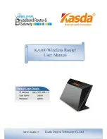
Page 2: ...Wireless Router User Guide ...

Page 3: ...ides you with fast always on internet access but is also an integral part of the network infrastructure Some routers may rely on others to reach the internet For this reason it is very important that you always keep your router powered ON even if you are not using it Your router may be forwarding and routing traffic for other routers in the network Components of your Nokia RoofTop Wireless Router ...

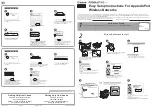
Page 4: ...4 Ethernet cable 5 Network Power Unit 2 1 3 4 5 6 ...

Page 5: ...s It complies with the FCC rules Part 15 Part 68 and with 21 CFR 1040 10 and 1040 11 Some routers may rely on others to reach the internet It is very important that your wireless router is always powered ON even when you are not using it as it may be forwarding and routing traffic for other routers in the network For this reason do not unplug your Network Power Unit ...

Page 6: ...pe of moisture including rain Do not use or install near water related environments such as sinks bathtubs laundry areas spas swimming pools or in wet basements Take care not to spill any liquids on the unit RF Exposure Disconnect power from the wireless router when working within 7 inches 16 cm of the antenna Grounding Be sure the wireless router and antenna system is grounded to provide protecti...

Page 7: ...et Place the cables so that they are not likely to be walked on or pinched by items placed on or against them Pay particular attention to the point where cords and plugs exit the unit Interference The wireless router can cause interference to and interfere with other devices operating in the 2 4 to 2 4835 GHz radio spectrum Service Only by Qualified Service Personnel Do not open the unit or reconf...

Page 8: ...ce personnel may ask you to refer to the LEDs on the Network Power Unit When you call make sure you can see the LEDs to be able to give the information to the service personnel 1 PWR LAN shows the local area network activity and that the unit power is ON 2 Anchor shows the status in the network and gives wireless link information if this light is off you may not have a connecti on to the internet ...

Page 9: ... BaseT Ethernet jack RJ 45 3 Router outdoor unit connection This connector connects directly to your outdoor wireless router Connecting the Wireless Router to Your PC LAN or Home PNA Your wireless router is capable of providing internet access for a single PC via a direct connection or to multiple PCs via Local Area Network LAN or via Home PNA 1 2 3 ...

Page 10: ...Network Power Unit s home PNA connection and the RJ11 phone jack You can also connect the cable directly to your PC s home PNA adapter The router automatically activates the Ethernet or home PNA depending upon which connector is used If a cable is connected to both connectors the Ethernet port is activated Technical Support Nokia provides technical support only for network operators and authorized...

Page 11: ...S OF USE OF THE PRODUCT OR ANY ASSOCIATED EQUIPMENT COST OF CAPITAL COST OF ANY SUBSTITUTE EQUIPMENT OR FACILITIES DOWNTIME THE CLAIMS OF ANY THIRD PARTIES INCLUDING CUSTOMERS AND INJURY TO PROPERTY RESULTING FROM THE PURCHASE OR USE OF THE PRODUCT OR ARISING FROM BREACH OF THE WARRANTY BREACH OF CONTRACT NEGLIGENCE STRICT TORT OR ANY OTHER LEGAL OR EQUITABLE THEORY EVEN IF NOKIA KNEW OF THE LIKEL...

Page 12: ...to telephone network FCC Part 68 This equipment complies with Part 68 of the FCC Rules The FCC Part 68 Label is located on the rear panel of the Network Power Unit This label contains among other information the FCC Registration Number and Ringer Equivalency Number REN for this equipment You must upon request provide this information to your telephone company The REN is useful to determine the qua...

Page 13: ...appropriate Terminal Equipment Technical document s The department does not guarantee the equipment will operate to the user s satisfaction Before installing this equipment users should ensure that it is permissible to be connected to the facilities of the local telecom munications company The equipment must also be installed using an acceptable method of connection The customer should be aware th...

Page 14: ...Wireless Router User Guide ...

Page 15: ...ith fast always on internet access but is also an integral part of the network infrastructure Some routers may rely on others to reach the internet For this reason it is very important that you always keep your router powered ON even if you are not using it Your router may be forwarding and routing traffic for other routers in the network Components of your Nokia RoofTop Wireless Router system You...

Page 16: ...4 Ethernet cable 5 Network interface and power supply unit 2 1 3 4 5 6 ...

Page 17: ...and 1040 11 This wireless router and its associated components are class B devices that must be installed and or moved by a professional Some routers may rely on others to reach the internet It is very important that your wireless router is always powered ON even when you are not using it as it may be forwarding and routing traffic for other routers in the network For this reason do not unplug you...

Page 18: ...upply unit to any type of moisture including rai n Do not use or install near water related environments such as sinks bathtubs laundry areas spas swimming pools or in wet basements Take care not to spill any liquids on the unit RF Exposure Disconnect power from the wireless router when working within 7 inches 16 cm of the antenna Grounding Be sure the wireless router and antenna system is grounde...

Page 19: ...ly unit to a grounded AC outlet Place the cables so that they are not likely to be walked on or pinched by items placed on or against them Pay particular attention to the point where cords and plugs exit the unit Interference The wireless router can cause interference to and interfere with other devices operating in the 2 4 to 2 4835 GHz radio spectrum Service Only by Qualified Service Personnel D...

Page 20: ...sk The service personnel may ask you to refer to the LEDs on the network interface and power supply unit When you call make sure you can see the LEDs to be able to give the information to the service personnel 1 PWR LAN shows the local area network activity and that the unit power is ON 2 Anchor shows the status in the network and gives wireless link information if this light is off you may not ha...

Page 21: ... BaseT Ethernet jack RJ 45 3 Router outdoor unit connection This connector connects directly to your outdoor wireless router Connecting the Wireless Router to Your PC LAN or Home PNA Your wireless router is capable of providing internet access for a single PC via a direct connection or to multiple PCs via Local Area Network LAN or via Home PNA 1 2 3 ...

Page 22: ... the network interface and power supply unit s home PNA connection and the RJ11 p hone jack You can also connect the cable directly to your PC s home PNA adapter The router automatically activates the Ethernet or home PNA depending upon which connector is used If a cable is connected to both connectors the Ethernet port is activated Technical Support Nokia provides technical support only for netwo...

Page 23: ...ES LOSS OF USE OF THE PRODUCT OR ANY ASSOCIATED EQUIPMENT COST OF CAPITAL COST OF ANY SUBSTITUTE EQUIPMENT OR FACILITIES DOW NTIME THE CLAIMS OF ANY THIRD PARTIES INCLUDING CUSTOMERS AND INJURY TO PROPERTY RESULTING FROM THE PURCHASE OR USE OF THE PRODUCT OR ARISING FROM BREACH OF THE WARRANTY BREACH OF CONTRACT NEGLIGENCE STRICT TORT OR ANY OTHER LEGAL OR EQUITABLE THEORY EVEN IF NOKIA KNEW OF TH...

Page 24: ...on to telephone network FCC Part 68 This equipment complies with Part 68 of the FCC Rules The FCC Part 68 Label is located on the rear panel of the NIPSU unit This label contains among other information the FCC Registration Number and Ringer Equivalency Number REN for this equipment You must upon request provide this information to your telephone company The REN is useful to determine the quantity...

Page 25: ...Technical document s The department does not guarantee the equipment will operate to the user s satisfaction Before installing this equipment users should ensure that it is permissible to be connected to the facilitiesof the local telecom munications company The equipment must also be installed using an acceptable method of connection The customer should be aware that compliance with the above con...

Page 26: ...Manual Professional Installation ...

Page 27: ...DN00290079 2nd Draft December 2000 Nokia RoofTop Wireless Router R240 R240A Hardware Installation Guide ...

Page 28: ...equipment has been tested and found to comply with the limits for a Class B digital device pursuant to Part 15 of the FCC rules These limits are designed to provide reasonable protection against harmful interference in a residential installation This equipment generates uses and can radiate radio frequency energy and if not installed and used in accordance with the instruc tions may cause harmful ...

Page 29: ... not be used on coin service provided by the telephone company Connection to party lines is subject to tariffs If trouble is experienced with this unit for repair or warranty information please contact customer service at the address and phone listed below If the equipment is causing harm to the network the telephone company may request that you disconnect the equipment until the problem is resolv...

Page 30: ...t the user to disconnect the equipment Notice The Ringer Equivalent Number REN assigned to each terminal device provides an indication of the maximum number of terminals allowed to be connected to a telephone interface The termination on an interface may consist of any combination of devices subject only to the requirement that the sum of the Ringer Equivalence Numbers of all the devices does not ...

Page 31: ...CTIONS AND STATEMENTS CONTAINED IN THE GUIDE OR ITS CONTENT ARE TRUE ACCURATE OR COMPLETE LIMITATION OF LIABILITY TO THE MAXIMUM EXTENT PERMITTED BY APPLICABLE LAW IN NO EVENT SHALL NOKIA ITS EMPLOYEES OR AFFILIATES BE LIABLE FOR ANY LOST PROFITS REVENUE SALES DATA OR COSTS OF PRO CUREMENT OF SUBSTITUTE GOODS OR SERVICES PROPERTY DAMAGE PERSONAL INJURY INTERRUPTION OF BUSINESS LOSS OF BUSINESS INF...

Page 32: ......

Page 33: ... steps 19 3 1 1 Line of sight analysis 21 3 1 2 Antenna selection 22 CHAPTER 4 Planning the installation 25 4 1 Main installation steps 25 4 1 1 To find a location for the router 26 4 1 2 To plan the Network Power Unit location 27 4 1 3 To plan the cable routing 27 4 1 4 To plan the grounding 27 CHAPTER 5 Outdoor installation 29 5 1 Introduction 29 5 1 1 Components to be installed 29 5 2 To instal...

Page 34: ...twork Power Unit 47 7 3 1 Connection options 50 7 3 2 Network 50 7 3 3 Direct personal computer connection 51 7 3 4 Home PNA connection 52 CHAPTER 8 Configuring the end user PC 53 8 1 Introduction 53 8 1 1 To configure the customer s personal computer 54 8 1 2 To configure the customer s Macintosh 54 CHAPTER 9 Post installation testing 55 9 1 Introduction 55 9 1 1 Functional testing 55 APPENDIX A ...

Page 35: ...Nokia RoofTop Wireless Router Installation Guide 9 Contents APPENDIX D Tool requirements 65 ...

Page 36: ...10 Nokia RoofTop Wireless Router Installation Guide Contents ...

Page 37: ...actual instructions for installation commence in Chapter 5 0 1 1 1 Task flowchart Shown below is a flowchart outlining the tasks required for the installation It is also intended to assist in quickly locating the principal topics within this document You can find detailed descriptions under their corresponding topics NOTE The Nokia RoofTop Wireless Router has to be pre configured by the Internet S...

Page 38: ...12 Nokia RoofTop Wireless Router Installation Guide ...

Page 39: ...Nokia RoofTop Wireless Router Installation Guide 13 Introduction ...

Page 40: ...14 Nokia RoofTop Wireless Router Installation Guide ...

Page 41: ...on It is important when installing the Nokia Wireless Router that the unit is not installed where it could be either damaged by its environment or pose a hazard for the user In this respect when installing the unit be aware of the following Hazard Warnings and Regulatory Safety Requirements ...

Page 42: ...install near water related environments such as sinks bathtubs laundry areas spas swimming pools or in wet basements Take care not to spill any liquids on the unit Use extreme caution when installing antennas in areas with overhead power lines Outdoor antennas and their supporting masts guy wires and cables are electrical conductors Contact with high voltage electrical wires can cause serious inju...

Page 43: ... in Appendix C The antenna detailed regulatory and safety requirements for antennas is available in Appendix C Co location In order to avoid degradation of performance it is recommended that the antennas be placed at least one meter 3 feet apart The Nokia RoofTop Wireless Router and its associated components must be installed and configured by a trained professional NOTE Awaiting table from Nokia ...

Page 44: ...18 Nokia RoofTop Wireless Router Installation Guide ...

Page 45: ... Determine the feasibility of RF links to other sites If the site has good links to other sites it can be used as a forwarding system for other wireless routers in the network If the router can link to one other router it will be able to access the internet but it will be unable to forward signals to other wireless routers Determine the RF path between the antenna at the site and the antennas at o...

Page 46: ...l antenna This ensures maximum connectivity and allows the system to forward packets of information for existing and future needs If the router requires a single link to another router use a directional antenna See also Section 3 1 1 Line of sight below 3 Select the antenna type to be used The wireless router is supplied with an omnidirectional antenna but on rare occasions a directional antenna m...

Page 47: ...uters It is recommended that each router has a line of sight to at least 2 other routers to enable several options to route internet traffic to the airhead Line of Sight and Fresnel Zone Illustration Visual line of sight Visual line of sight exists when an imaginary straight line can be drawn between two antennas without passing through any physical obstructions Verifying visual line of sight is t...

Page 48: ... distances wooden structures and non metallic objects have little effect on the RF signal For long distance paths there should be no obstacles close to the RF path 3 1 1 2 To determine line of sight 1 Access the rooftop using a safe ladder either tied or held by another surveyor 2 Scan the other rooftops in the location Ensure line of sight ensuring that other routers can be seen from the selected...

Page 49: ...sed at all forwarding sites Omnidirectional antennas are the preferred solution to most installations Omnidirectional Antenna RF Radiation Pattern 3 1 2 3 Directional antennas Directional Antennas focus the RF beam in narrow patterns in one direction and provide communication over greater distances than omnidirectional antennas but they are limited in the areas they cover NOTE Directional antennas...

Page 50: ... 2 4 Notes on antenna polarization Polarization refers to the direction of antenna element alignment For antennas to properly communicate with each other all antenna must be aligned polarized in the same direction Omnidirectional antenna This vertically polarized antenna can only be mounted vertically Directional antenna Polarization is identified by an arrow on the rear panel Radiates from the fr...

Page 51: ...tallation consists of five basic steps 1 The Nokia roofTop Wireless Router 2 The Multiwire connection between the router and the Network Power Unit 3 The Network Power Unit 4 The grounding where required 5 The indoor connections between the Network Power Unit and the computer s in the property NOTE Digital picture of components to be inserted here ...

Page 52: ...router the highest point on the roof should be used to ensure a clear line of site Existing structures like chimneys pipes tv antenna poles etc should be used for mounting the router Only if there is no suitable mounting point should a mounting pole be used Height of the antenna is often limited to physical limitations of the site For example an antenna mast can be placed on a rooftop or installed...

Page 53: ...e route of the multiwire cabling The proximity of a telephone connection point where applicable for HomePNA 4 1 3 To plan the cable routing Take into account the customers wishes for cable routing Avoid pipes downspouts and possible areas which may abrade the cabling For further details see Chapter 6 Routing the cable into the property 4 1 4 To plan the grounding Test the existing grounding system...

Page 54: ...28 Nokia RoofTop Wireless Router Installation Guide ...

Page 55: ...quired Router mounting hardware Antenna if non integral and mounting hardware A shielded multiwire cable containing 7 twisted pairs of wires This is used to connect the wireless router with the NPU Nokia provides several different lengths of cable with D Connectors already installed to the end of the cable The multiwire cable must be Cat 5 cable size AWG 22 or 24 Flexible RF cable in the case of n...

Page 56: ... into house Check with Petri 5 1 1 1 RF cable for non integral antenna Nokia provides a flexible jumper cable for the connection between a router and a directional antenna NOTE When using an RF cable instead of the integral antenna a special RF adapter must be used Nokia Code WR 468993A ...

Page 57: ...ess router bracket to the mounting point ensuring that the bracket is fixed securely Where the installation is for a directional antenna mount the router bracket approximately 18 inches below the top of the mast NOTE For directional antenna information see Section 5 2 1 Directional antenna Router bracket fixed to mast ...

Page 58: ...irectional antenna by screwing it into the top of the wireless router Carefully guide the antenna down onto the RF pin to prevent the pin being bent out of shape Ensure secure connection but do not overtighten Definition of overtighten Attach the omni directional antenna ...

Page 59: ...nd wire NOTE Take care when tightening the D Connector to the router It is easy to damage the router casing if the screws are overtightened 4 Using cable ties and or adhesive tape secure the multiwire connection and ground wire where used to the mast Take care to avoid placing strain on the connectors when securing the cables to the mast Use ties tape about every two feet down the length of the ma...

Page 60: ...uide 5 Attach mounting bracket to back of router Ensure that the bolt fits correctly and is not cross threaded There is no need to tighten the bolt play is required to attach the router to the mast mounting bracket Attach mounting bracket to router ...

Page 61: ...Nokia RoofTop Wireless Router Installation Guide 35 To install the router 6 Attach the front panel of the wireless router Attach front panel of wireless router ...

Page 62: ...at the router is mounted perfectly vertical on the mount using a level as necessary and tighten the bolt in the back of the router Be careful not to overtighten the bolt Overtightening of the bolt will strip the thread in the back of the aluminum casting of the wireless router Slide the router mount onto the mast bracket ...

Page 63: ...top part of the mast using the mounting clamp Tighten the nuts to fasten the antenna securely 2 Using the Jumper Cable pigtail connect the wireless router to the directional antenna ensuring that the connections are properly tight but do not overtighten Connect the wireless router to the directional antenna with the jumper cable ...

Page 64: ...enters the cable or connector it will significantly reduce the signal levels and can ruin the cable and connectors 4 Cut an 8 strip of weatherproofing tape and remove the plastic backing from the tape Remove plastic backing from the tape 5 Stretch and apply the tape in the direction of the connector thread to ensure that the connector does not come loose during the weatherproofing process Stretchi...

Page 65: ...tenna and the top of the connector without gaps and with a layer of overlapping This is an area where water can enter the connector and cable NOTE Make sure you apply the tape in the direction of the threads Covering the directional antenna connection with weatherproof tape NOTE Squeeze the tape against the antenna and connector to remove any air gaps and apply the tape so that it overlaps half of...

Page 66: ...out gaps and with a layer of overlapping This is an area where water can enter the connector and cable Covering the Router connection with weatherproof tape NOTE Care should be taken when weatherproofing RF connectors Do not stress or bend the cable during the weatherproofing process 8 Attach the mast where applicable to the property securely and as appropriate to the requirements of the site Ensu...

Page 67: ...ground to the router provides a path for the lightning 1 Connect the grounding box connector marked Surge towards the antenna and the connector marked Protected to the Network Power Unit NPU end of the cabling 2 Protect the connections as previously described using weatherproofing tape 3 Locate the lightning arrestor close to the point of entry to the home 4 Provide a good very low resistance wire...

Page 68: ...42 Nokia RoofTop Wireless Router Installation Guide Grounding of router and NPU ...

Page 69: ...s water and gas pipes Try to use existing entries into the home to avoid having to drill holes Try to make the cable entry to the computer connections as close to the customers PC as possible using the shortest cable possible Where wires have to be routed outside of the building make sure that they are supported with cable clips at 18 to 24 inch intervals and are not unsightly Make sure that there...

Page 70: ...44 Nokia RoofTop Wireless Router Installation Guide ...

Page 71: ... Installation Guide 45 CHAPTER 7 Indoor installation 7 1 Introduction 7 1 1 Components to be installed The Indoor portion of the Nokia Wireless Router System consists of Network Power Unit NPU Ethernet or home PNA connection cable ...

Page 72: ...it NPU 1 HomePNA 2 0 interface a standard phone jack RJ 11 2 Ethernet interface a standard 10 100 BaseT Ethernet jack RJ 45 3 Router outdoor unit connection A multiwire cable from Router unit is connected to this The connector is a punch down connector inside the unit 1 3 2 ...

Page 73: ...er wires in the cable 2 Remove the Network Power Unit from its packaging and loosen the strain relief the unit is already disassembled 3 Place the cable through the strain relief and slot the appropriate wire into the appropriate slot in the connection Using the punch down tool fix the wire into the Network Power Unit NOTE Place illustration of connectors here 4 When all wires are connected secure...

Page 74: ...d to the router 7 Connect the ethernet cable from the Network Power Unit to the PC or home PNA adapter or network hub NOTE Shielded ethernet cables must be used on all installations The LEDs indicate the following information LED Description Power LAN Solid On Power on but no ethernet packets seen Slow Flash Waiting for the router to complete boot cycle Intermittent Flash Off during packet transmi...

Page 75: ...o 3 hops Fast Flash More than 3 hops to the AirHead or The unit has neighbors but there is no path to the AirHead Off The router has no neighbors Network Solid On More than or equal to 2 independent neighbors with at least one 2Mbps path to the AirHead and the path to the AirHead is less than or equal to3 hops Slow Flash Greater than or equal to 2 independent neighbors with a 1 Mbps path to the Ai...

Page 76: ... 10 100bT ethernet crossover cable Home PNA Connection The Router automatically activates the ethernet or Home PNA depending upon which connector is used If the cable is connected to both connectors the ethernet port is activated All these options are described in more detail below 7 3 2 Network Use a standard Ethernet Cable with an RJ45 connector at the Wireless Router and the appropriate connect...

Page 77: ...ork Power Unit and the appropriate connector for the Personal Computer Ethernet connection See appendix for wiring diagram for crossover cable Connect the Network Power Unit computer and LAN as shown in the following diagram Use one crossover cable whenever a network hub is not being used and always use it at the PC Direct PC connection NOTE Changing the Ethernet configuration from a LAN connectio...

Page 78: ...nstallation Guide 7 3 4 Home PNA connection Connect the phone cable between a Network Power Unit HomePNA connection and RJ11 phone jack or directly to the PC HomePNA adapter Connect PC to adapter according to manufacturers instructions ...

Page 79: ... customers PC needs to be configured for use with the Nokia Wireless Router system The customer may carry out the configuration themselves or the installer may be required to carry out the configuration for the customer This depends upon the agreement with the Internet Service Provider The ISP provide all the information required prior to installation ...

Page 80: ...e a NIC either install it or help the customer to install it depending on what has been agreed with the ISP 2 Define the TCP IP Properties In the IP Address field either select the Obtain IP Address Automatically or enter the IP Address and Subnet Mask in accordance with information provided by the ISP 3 In the Default Gateway field enter the IP address of the default gateway provided by the ISP 8...

Page 81: ... the test follow the procedure shown below 9 1 1 Functional testing Ensure that the router functions correctly by carrying out the following 1 Ensure that the NPU is inserted properly into the AC outlet The LEDs flash three times to indicate that the router is functioning correctly 2 Turn on the customer s PC Wait for 3 5 minutes to allow the router to anchor to the network 3 Check the LEDs to ind...

Page 82: ...for the AOL browser to perform correctly The router supports only Netscape and Internet Explorer browsers 5 Check the data speed by placing a throughput test to www 2wire com Generally speeds of 200kb are acceptable but are not reflective of the performance of the router 6 Where there are problems with download or speed of connection check the installation first If this does not solve the problem ...

Page 83: ...Nokia RoofTop Wireless Router Installation Guide 57 Introduction ...

Page 84: ...58 Nokia RoofTop Wireless Router Installation Guide ...

Page 85: ...r Installation Guide 59 APPENDIX A Cables Ethernet crossover cable The wiring for an Ethernet Crossover cable for 10Base T is as follows RJ45 Plug Pin 1 Tx to Pin 3 Rx Pin 2 Tx to Pin 6 Rx Pin 3 Rx to Pin 1 Tx Pin 6 Rx to Pin 2 Tx ...

Page 86: ...60 Nokia RoofTop Wireless Router Installation Guide ...

Page 87: ... Unit Data Capacity per Cell 12 Mbps 6x2 Mbps per channel AirHeads per Cell Routers per Cell Routers per AirHead Up to 6 Up to 240 Up to 40 Antenna Type typical 8 dBi Omnidirectional integrated Link Range typical 1 Mbps Data Rate 2 Mbps Data Rate 1 75 Miles 0 50 Miles Radio Modem Specifications Frequency Band GHz Radio Type Modulation 2 4000 2 4835 Frequency Hopping Spread Spectrum 2 and 4 level G...

Page 88: ...r Environment Operational Temperature Relative Humidity 40o C to 55o C 40o to 131o F 100 Weight Router Dimensions 3 3 lbs inluding antenna and mount Router 4 W x 23 8 D x 81 4 H NPU 13 4 W x 23 4 D x 51 2 H Antenna 8dBi 211 2 H x 3 4 Diameter Power Consumption 16 Watts 120 VAC External Power Supply NA Management Nokia Wireless Router Manager SNMP MIB II Telnet Internet Protocols IP TCP UDP ICMP RI...

Page 89: ... from persons If wireless rouers are installed closer than 1 meter 3 feet apart horizontally the exposure distance must be read from the table below NOTE It is not recommended that wireless routers be installed closer than 1 meter apart horizontally unless more than 1 meter vertical separation is used Antennas 1 2 3 4 5 6 MPE Cm 16 cm 22 cm 27 cm 31 cm 35 cm 38 cm Distance Inches 7 inches 9 inches...

Page 90: ...64 Nokia RoofTop Wireless Routing Installation Guide ...

Page 91: ...Nokia RoofTop Wireless Routing Installation Guide 65 APPENDIX D Tool requirements ...

Page 92: ...66 Nokia RoofTop Wireless Routing Installation Guide ...

Page 93: ...Manual User Installation ...

Page 94: ...Nokia RoofTop Wireless Router R240 R240A Hardware Installation Guide self install ...

Page 95: ...equipment has been tested and found to comply with the limits for a Class B digital device pursuant to Part 15 of the FCC rules These limits are designed to provide reasonable protection against harmful interference in a residential installation This equipment generates uses and can radiate radio frequency energy and if not installed and used in accordance with the instruc tions may cause harmful ...

Page 96: ...ot be used on coin service provided by the telephone company Connection to party lines is subject to tariffs If trouble is experienced with this unit for repair or warranty information please contact customer service at the address and phone listed below If the equipment is causing harm to the network the telephone company may request that you disconnect the equipment until the problem is resolved...

Page 97: ...t the user to disconnect the equipment Notice The Ringer Equivalent Number REN assigned to each terminal device provides an indication of the maximum number of terminals allowed to be connected to a telephone interface The termination on an interface may consist of any combination of devices subject only to the requirement that the sum of the Ringer Equivalence Numbers of all the devices does not ...

Page 98: ...CTIONS AND STATEMENTS CONTAINED IN THE GUIDE OR ITS CONTENT ARE TRUE ACCURATE OR COMPLETE LIMITATION OF LIABILITY TO THE MAXIMUM EXTENT PERMITTED BY APPLICABLE LAW IN NO EVENT SHALL NOKIA ITS EMPLOYEES OR AFFILIATES BE LIABLE FOR ANY LOST PROFITS REVENUE SALES DATA OR COSTS OF PRO CUREMENT OF SUBSTITUTE GOODS OR SERVICES PROPERTY DAMAGE PERSONAL INJURY INTERRUPTION OF BUSINESS LOSS OF BUSINESS INF...

Page 99: ......

Page 100: ... find a location for the router 18 3 1 2 To plan the Network Power Unit location 19 3 1 3 To plan the cable routing 19 3 1 4 To plan the grounding 19 CHAPTER 4 Outdoor installation 21 4 1 Introduction 21 4 1 1 Components to be installed 21 4 2 To install the router 22 4 2 1 To prepare and install grounding 28 CHAPTER 5 Routing the cable into the property 31 5 1 General guidelines on cable routing ...

Page 101: ...twork 38 6 3 3 Direct personal computer connection 39 6 3 4 Home PNA connection 40 CHAPTER 7 Configuring the end user PC 41 7 1 Introduction 41 7 1 1 To configure the your personal computer 42 CHAPTER 8 Post installation testing 43 8 1 Introduction 43 8 1 1 Functional testing 43 APPENDIX A Cables 45 APPENDIX B Technical Specifications 47 ...

Page 102: ...Nokia RoofTop Wireless Router Installation Guide 9 CHAPTER 1 About this document 1 1 Introduction This document explains the procedures necessary to install the Nokia Rooftop Wireless Router ...

Page 103: ...10 Nokia RoofTop Wireless Router Installation Guide ...

Page 104: ...on It is important when installing the Nokia Wireless Router that the unit is not installed where it could be either damaged by its environment or pose a hazard for the user In this respect when installing the unit be aware of the following Hazard Warnings and Regulatory Safety Requirements ...

Page 105: ...aution when installing antennas in areas with overhead power lines Outdoor antennas and their supporting masts guy wires and cables are electrical conductors Contact with high voltage electrical wires can cause serious injury or death Because antennas and wireless routers are elevated metal objects with connections to ground they attract lightning Attach a grounding wire to the antenna and router ...

Page 106: ...eless Router Installation Guide 15 Regulatory safety requirements 2 3 Regulatory safety requirements RF exposure When the Network Power Unit is plugged in do not go closer than 7 inches 17 cm of the antenna on the roof ...

Page 107: ...16 Nokia RoofTop Wireless Router Installation Guide ...

Page 108: ...complete wireless router installation consists of five basic steps 1 The Nokia roofTop Wireless Router 2 The Multiwire connection between the router and the Network Power Unit 3 The Network Power Unit 4 The grounding where required 5 The indoor connections between the Network Power Unit and the computer s in the property ...

Page 109: ...should be used to ensure a clear line of sight Existing structures like chimneys pipes tv antenna poles etc should be used for mounting the router Only if there is no suitable mounting point should a mounting pole be used Height of the antenna is often limited to physical limitations of the site For example an antenna mast can be placed on a rooftop or installed on an existing structure or tower A...

Page 110: ...imity of a telephone connection point where applicable for HomePNA or routing of the Ethernet cable 3 1 3 To plan the cable routing Avoid pipes downspouts and possible areas which may abrade the cabling For further details see Chapter 6 Routing the cable into the property 3 1 4 To plan the grounding Test the existing grounding system at the property Where the existing grounding is not acceptable c...

Page 111: ...20 Nokia RoofTop Wireless Router Installation Guide ...

Page 112: ...ter system comprises Wireless router with integral antenna Grounding kit for router if required Router mounting hardware A shielded multiwire cable containing 7 twisted pairs of wires This is used to connect the wireless router with the NPU Nokia provides several different lengths of cable with D Connectors already installed on the end of the cable RF Cable adaptor Nokia Code WR 46899A ...

Page 113: ...Nokia RoofTop Wireless Router Installation Guide 4 2 To install the router 1 Mount the wireless router bracket to the mounting point ensuring that the bracket is fixed securely Router bracket fixed to mast ...

Page 114: ...ll the router 2 Attach the antenna by screwing it into the top of the wireless router Carefully guide the antenna down onto the RF pin to prevent the pin being bent out of shape Ensure secure connection but do not overtighten Attach the omni directional antenna ...

Page 115: ...crews are overtightened 4 Using cable ties and or adhesive tape secure the multiwire connection and ground wire where used to the mast Take care to avoid placing strain on the connectors when securing the cables to the mast Use ties tape about every two feet down the length of the mast Always cover the cable ties with electrical tape to prevent excess pressure on the D connector should the cable t...

Page 116: ...Nokia RoofTop Wireless Router Installation Guide 25 To install the router Attach mounting bracket to router ...

Page 117: ...26 Nokia RoofTop Wireless Router Installation Guide 6 Attach the front panel of the wireless router Attach front panel of wireless router ...

Page 118: ...ake sure that the router is mounted perfectly vertical on the mount using a level as necessary and tighten the bolt in the back of the router Be careful not to overtighten the bolt Overtightening of the bolt will strip the thread in the back of the aluminum casting of the wireless router Slide the router mount onto the mast bracket ...

Page 119: ...he router provides a path for the lightning 1 Connect the grounding box connector marked Surge towards the antenna and the connector marked Protected to the Network Power Unit NPU end of the cabling 2 Protect the connections as previously described using weatherproofing tape 3 Locate the lightning arrestor close to the point of entry to the home 4 Provide a good very low resistance wire connection...

Page 120: ...Nokia RoofTop Wireless Router Installation Guide 29 To install the router Grounding of router and NPU ...

Page 121: ...30 Nokia RoofTop Wireless Router Installation Guide ...

Page 122: ...isting entries into your home to avoid having to drill holes Try to make the cable entry to the computer connections as close to the your PC as possible using the shortest cable possible Where wires have to be routed outside of the building make sure that they are supported with cable clips at 18 to 24 inch intervals and are not unsightly Make sure that there is a drip loop at the point of entry t...

Page 123: ...32 Nokia RoofTop Wireless Router Installation Guide ...

Page 124: ... Installation Guide 33 CHAPTER 6 Indoor installation 6 1 Introduction 6 1 1 Components to be installed The Indoor portion of the Nokia Wireless Router System consists of Network Power Unit NPU Ethernet or home PNA connection cable ...

Page 125: ...it NPU 1 HomePNA 2 0 interface a standard phone jack RJ 11 2 Ethernet interface a standard 10 100 BaseT Ethernet jack RJ 45 3 Router outdoor unit connection A multiwire cable from Router unit is connected to this The connector is a punch down connector inside the unit 1 3 2 ...

Page 126: ...hrough the strain relief and slot the appropriate wire into the appropriate slot in the connection Using the punch down tool fix the wire into the Network Power Unit 4 When all wires are connected securely reconnect the cable strain relief in the unit to prevent the multiwire cable from being pulled out of the unit 5 Replace the Network Power Unit cover and replace the screws Do not overtighten th...

Page 127: ...Shielded ethernet cables must be used on all installations The LEDs indicate the following information LED Description Power LAN Solid On Power on but no ethernet packets seen Slow Flash Waiting for the router to complete boot cycle Intermittent Flash Off during packet transmit or receive Otherwise ON Off No power or the router is not functioning IROS is off ...

Page 128: ...o 3 hops Fast Flash More than 3 hops to the AirHead or The unit has neighbors but there is no path to the AirHead Off The router has no neighbors Network Solid On More than or equal to 2 independent neighbors with at least one 2Mbps path to the AirHead and the path to the AirHead is less than or equal to3 hops Slow Flash Greater than or equal to 2 independent neighbors with a 1 Mbps path to the Ai...

Page 129: ... 10 100bT ethernet crossover cable Home PNA Connection The Router automatically activates the ethernet or Home PNA depending upon which connector is used If the cable is connected to both connectors the ethernet port is activated All these options are described in more detail below 6 3 2 Network Use a standard Ethernet Cable with an RJ45 connector at the Wireless Router and the appropriate connect...

Page 130: ...ork Power Unit and the appropriate connector for the Personal Computer Ethernet connection See appendix for wiring diagram for crossover cable Connect the Network Power Unit computer and LAN as shown in the following diagram Use one crossover cable whenever a network hub is not being used and always use it at the PC Direct PC connection NOTE Changing the Ethernet configuration from a LAN connectio...

Page 131: ...nstallation Guide 6 3 4 Home PNA connection Connect the phone cable between a Network Power Unit HomePNA connection and RJ11 phone jack or directly to the PC HomePNA adapter Connect PC to adapter according to manufacturers instructions ...

Page 132: ...ide 41 CHAPTER 7 Configuring the end userPC 7 1 Introduction After the router installation is complete your PC needs to be configured for use with the Nokia Wireless Router system The ISP provides all the information required prior to installation ...

Page 133: ... the PC has a network interface card NIC If the PC does not have a NIC install it 2 Define the TCP IP Properties In the IP Address field either select the Obtain IP Address Automatically or enter the IP Address and Subnet Mask in accordance with information provided by the ISP 3 In the Default Gateway field enter the IP address of the default gateway provided by the ISP ...

Page 134: ...out the test follow the procedure shown below 8 1 1 Functional testing Ensure that the router functions correctly by carrying out the following 1 Ensure that the NPU is inserted properly into the AC outlet The LEDs flash three times to indicate that the router is functioning correctly 2 Turn on your PC Wait for 3 5 minutes to allow the router to anchor to the network 3 Check that the LEDs indicate...

Page 135: ...e dial up connections for the AOL browser to perform correctly The router supports only Netscape and Internet Explorer browsers 5 Check the data speed by placing a throughput test to www 2wire com Generally speeds of 200kb are acceptable 6 Where there are problems with download or speed of connection check the installation first If this does not solve the problem then contact the ISP ...

Page 136: ...r Installation Guide 47 APPENDIX A Cables Ethernet crossover cable The wiring for an Ethernet Crossover cable for 10Base T is as follows RJ45 Plug Pin 1 Tx to Pin 3 Rx Pin 2 Tx to Pin 6 Rx Pin 3 Rx to Pin 1 Tx Pin 6 Rx to Pin 2 Tx ...

Page 137: ...48 Nokia RoofTop Wireless Router Installation Guide ...

Page 138: ...nted Unit Data Capacity per Cell 12 Mbps 6x2 Mbps per channel AirHeads per Cell Routers per Cell Routers per AirHead Up to 6 Up to 240 Up to 40 Antenna Type 8 dBi Omnidirectional integrated Link Range typical 1 Mbps Data Rate 2 Mbps Data Rate 1 75 Miles 0 50 Miles Radio Modem Specifications Frequency Band GHz Radio Type Modulation 2 4000 2 4835 Frequency Hopping Spread Spectrum 2 and 4 level GF SK...

Page 139: ...ter Environment Operational Temperature Relative Humidity 40o C to 55o C 40o to 131o F 100 Weight Router Dimensions 3 3 lbs inluding antenna and mount Router 4 W x 23 8 D x 81 4 H NPU 13 4 W x 23 4 D x 51 2 H Antenna 8dBi 211 2 H x 3 4 Diameter Power Consumption 16 Watts 120 VAC Management Nokia Wireless Router Manager SNMP MIB II Telnet Internet Protocols IP TCP UDP ICMP RIPv1 RIPv2 SNMP TFTP IGM...

Reviews: