Nokia G-2426G-B, Product Manual
The Nokia G-2426G-B Product Manual is essential for setting up and optimizing your device. This comprehensive manual can be effortlessly downloaded for free at manualshive.com, providing step-by-step instructions and insightful tips to enhance your user experience. Don't miss the chance to explore the full potential of your Nokia G-2426G-B!
Share
Download

Reviews:
No comments
Related manuals for G-2426G-B
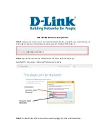
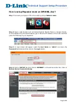
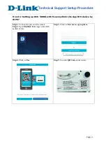
DSL-2750U
Brand: D-Link Pages: 3
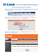
DSL-2750U
Brand: D-Link Pages: 3
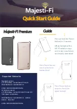
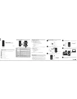
Premium
Brand: Majesti-Fi Pages: 2
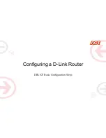
AC1200
Brand: D-Link Pages: 2
DIR-868L
Brand: D-Link Pages: 3

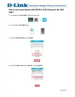
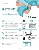
COVR-C1200
Brand: D-Link Pages: 24

DIR-868L
Brand: D-Link Pages: 59
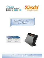
KA300
Brand: Kasda Pages: 42
MP980 series
Brand: Canon Pages: 4
DCS-5000L
Brand: D-Link Pages: 3
N300
Brand: D-Link Pages: 2
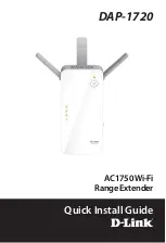
DAP-1720
Brand: D-Link Pages: 24
COVR-C1203
Brand: D-Link Pages: 6
DIR-850L
Brand: D-Link Pages: 13
COVR-2202
Brand: D-Link Pages: 2
SharePort DIR-825
Brand: D-Link Pages: 20
AirPlus DI-714P+
Brand: D-Link Pages: 5
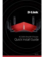
AC5300
Brand: D-Link Pages: 12


