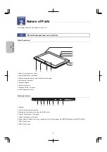
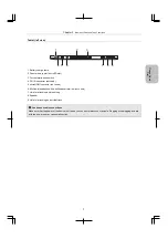
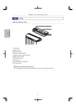
background image


Other

Information


Cha

nging 

Settings 

Scale, Ann

ota

tion,

and Me

asur

ement


F

unctions


Photog

rap
hing

 and


Replayi

ng Ima

ges
 

Photographi

ng


Bas

ics

 of DS

-L4 

Please Rea

d

First


DS-L4 


Microscope Camera Control Unit 

Instructions 

Camera Operation 


M668 E


16.9.Nx.1 (1/2)

Summary of Contents for DS-L4

Page 1: ...ng Settings Scale Annotation and Measurement Functions Photographing and Replaying Images Photographing Basics of DS L4 Please Read First DS L4 Microscope Camera Control Unit Instructions Camera Operation M668 E 16 9 Nx 1 1 2 ...

Page 2: ......

Page 3: ...ogether with this icon This icon marks precautions or information that should be observed to avoid malfunction and failure of this product This icon marks notes or information that should be read before use It also marks tips or additional information that may be helpful when using this product Trademarks in this manual Windows is a registered trademark of Microsoft Corporation in the United State...

Page 4: ...a and folder in which you want to save images Output to an external display Images can be output to any commercially available WUXGA external display via the analog RGB or DisplayPort interface Consecutive capture with an interval timer Multiple images can be automatically captured at intervals by specifying the number of images and the interval length This function allows you to observe how a sub...

Page 5: ... 3 Connecting an external display 12 3 2 4 Connecting USB Peripheral Devices 13 3 3 Connecting the AC Adapter 14 Preparing for Use 15 4 1 Starting Closing DS L4 15 4 1 1 Starting the DS L4 15 4 1 2 Switching Off 17 4 2 Setting the Display Language 18 4 2 1 Setting the Display Language 18 4 3 Preparing Recording Media 19 4 3 1 Handling Recording Media 19 4 3 2 Using a MicroSD Card 21 4 3 3 Connecti...

Page 6: ...vation 50 Part3 Photographing and Replaying Images Capturing Images with Advanced Setting Menu 52 8 1 Basic Operations of Photographing 52 8 1 1 Using a scene mode or custom setting 52 8 1 2 Adjusting the Exposure 55 8 1 3 Capturing Displayed Images 58 8 2 Setting Detailed Photographing Conditions 61 8 2 1 Setting items of the CAMERA MENU CAMERA screen 61 8 2 2 Setting Items of the CAMERA MENU IMA...

Page 7: ...126 12 2 3 Measuring an Angle 127 12 2 4 Measuring the Diameter of a Circle 128 12 2 5 Measuring the Area of a Polygon 129 12 2 6 Measuring the Length Between the Centers of Two Circles 130 12 2 7 Measuring a Pitch 131 12 3 Operations That Can Be Performed for Measurement Results 132 12 3 1 Erasing All Measurement Results 132 12 3 2 Exporting Measurement Results to a CSV File 132 Part 5 Changing S...

Page 8: ... point 169 15 6 Specifying the file sharing settings on the external information terminal side 170 Troubleshooting 172 16 1 Power Supply 172 16 2 Image Output 172 16 3 View of Images 173 16 4 Saved Image Quality 175 16 5 Image Saving 175 16 6 System Operation 176 16 7 Network 176 16 8 Warning Messages 177 16 9 For Inquiries 179 Performing Captures from an External Device 180 Using the Diagnostic P...

Page 9: ...the first time please read this part Also refer to this part whenever you want to confirm basic operations during installation and connection of the DS L4 or during actual operation of the DS L4 This part consists of the following chapters Chapter 1 Before Use Chapter 2 Names of Parts Chapter 3 Installation and Connection Chapter 4 Preparing for Use Chapter 5 Using Menus ...

Page 10: ...tained in the packing box Please make sure that you have everything If any items are missing contact your nearest Nikon representative immediately No Item No Item 1 DS L4 Microscope Camera Control Unit Tablet main body 4 AC adapter for the cradle supplied with the cradle 2 Cradle supplied separately from the tablet main body 5 Power cord for the cradle supplied with the cradle 3 Instruction manual...

Page 11: ... The characteristics of the microscope camera differ depending on the model Before using a camera confirm that it is a supported model Supported Microscope Cameras Model Image Pickup Device Mount Cooling Body Color DS Fi3 1 1 8 inch color 5 9 M pixels C mount Black Note For the specifications of each individual microscope camera refer to the respective manual ...

Page 12: ...s equivalent to those of the touch panel For operation of menus on an external display a mouse is required Use mouse operation for adding lines and comments to images Annotation function and measuring lengths and angles on the screen Measurement function Please use a model whose operation is verified by Nikon Not every USB mouse is compatible with the DS L4 5 USB keyboard A connected USB keyboard ...

Page 13: ...or higher With the DS L4 connected to the network you can save image files in a PC through the network and control the DS L4 from a PC Network cables Use a shielded cable that satisfies EMC standards When connecting the DS L4 to a LAN use a straight cable When connecting the DS L4 to a PC use a crossover cable Tightly connect the network cable If the network cable is removed while the DS L4 is bei...

Page 14: ...tus of the Web camera not used 4 Web camera not used 5 Wireless antenna 6 Docking connector 7 Windows button not used 8 LCD display touch panel Tablet right view 1 2 3 4 5 6 7 8 1 Speaker 2 Hole for attaching a stylus string 3 Shortcut button used only to open the BIOS menu 4 Volume Down button not used 5 Volume Up button not used 6 Power button Used only to turn on the power To turn off the power...

Page 15: ...DC IN connector not used 5 microHDMI connector not used 6 Mic line in headphone line out headset terminal not used 7 Hole for attaching a stylus string 8 Speaker 9 Hole for attaching an anti theft lock Cautions on cable connections Make sure that the power of the device is off when you connect or disconnect a cable Plugging or unplugging a cable with the power on may cause malfunction ...

Page 16: ... connector 3 USB 2 0 connector 4 Mic line in terminal not used 5 Headphone line out terminal not used 6 Analog display connector 7 DisplayPort connector 8 LAN connector 9 Hole for attaching an anti theft lock 10 DC IN connector About the external display connectors The analog display connector and the DisplayPort connector cannot be used concurrently ...

Page 17: ...blet squarely on the cradle aligning the two projections of the cradle with their corresponding holes 2 Incline the tablet towards the cradle slightly 3 Holding the tablet s top corners push the tablet forward until you hear a click Make sure that the tablet and cradle are connected securely the tablet is inclined at the angle of the cradle front panel Place the cradle on a stable horizontal surfa...

Page 18: ...s turned off before plugging or unplugging cables Connecting a cable when the power is on may cause electric shock or malfunction or failure of the device 3 2 1 Connection Overview Bluetooth USB 2 0 microSD DisplayPort D sub15 pin USB 2 0 USB 2 0 USB 3 0 Wi Fi LAN Network Connection overview USB memory drive Viewer terminal tablet or PC Network drive External display Camera Microscope Wi Fi access...

Page 19: ... while the DS L4 is active may cause malfunction 1 Make sure that the DS L4 power is turned off 2 Use a commercially available USB 3 0 cable to connect the USB 3 0 connector of the tablet and the USB type D connector of the microscope camera Use a USB 3 0 interface to connect the camera The camera must be connected to the USB 3 0 connector on the upper right side of the DS L4 main body Connecting ...

Page 20: ...20 x 1200 pixels use the DisplayPort interface or analog display connector of the cradle 1 Make sure that power to the DS L4 and the external display to be connected is turned off 2 Use a commercially available cable to connect the DisplayPort or analog display connector of the cradle with the video input terminal of the external display Connecting an external display to the DS L4 About the extern...

Page 21: ...nnected to cascaded USB hubs are not recognized If the USB keyboard you use has a USB hub use the hub of the keyboard For Nikon microscopes that can be connected to the DS L4 refer to 20 1 DS L4 Microscope Camera Control Unit Mouse speed The mouse pointer speed of the connected USB mouse can be specified in the DS SETUP menu For details refer to 13 2 5 2 Setting the mouse pointer speed Using a key...

Page 22: ...ther power cord may cause malfunction or fire For details on the power cord that can be used refer to Chapter 20 Main Specifications This device is designated under electric shock protection class I and therefore must only be connected to an AC outlet that has a protective ground terminal If the power cord is lost or damaged contact the place of purchase 1 Make sure that the DS L4 power is turned ...

Page 23: ...icroscope before switching on the DS L4 For details on how to switch on the microscope refer to the manual of the microscope 1 Press the power button to turn on the DS L4 power Hold down the power button for about two seconds until the button vibrates Before the login screen or a live image with a menu is displayed a black screen may appear or the screen may freeze temporarily However this phenome...

Page 24: ...visors can change the settings in the DS SETUP and MIC SETUP menus If no user account is registered no one can connect to the DS L4 and retrieve images from a viewer terminal Changing the password In the login screen enter your ID and password and then tap PASSWORD CHANGE You can then set a new password If you enter an incorrect password five times If you enter an incorrect password five times you...

Page 25: ... or VIEW menu tap SETTINGS 2 Tap SHUT DOWN The power is turned off If a blue or black screen appears Infrequently a blue or black screen may appear for one minute or a longer time before the power is turned off In such a case there is no problem with the system and please wait a while 1 2 ...

Page 26: ... to Chapter 13 Changing Settings 4 2 1 Setting the Display Language 1 Tap SETTINGS 2 Tap DS SETUP The MAIN screen appears 3 Tap LANGUAGE 4 Select the desired language The selected language will be indicated on the LANGUAGE button 5 Tap SAVE to save the setting The display language is changed 6 To close the DS SETUP screen tap x in the top right of the screen Setting the display language 3 5 6 1 2 ...

Page 27: ... a microSD card or USB memory drive Carefully read the instructions for the recording media to be used Insert the recording media in the correct orientation Do not remove the recording media or turn off the power while data is being written Doing so may cause loss of data or malfunction of the media Some types of recording media might not operate properly Use media whose operation has been verifie...

Page 28: ...ng media devices and to switch the storage folder and playback folder Before you start capturing images you must specify the recording media and folder as the storage location for the captured images For details about setting the image storage location refer to 8 2 3 7 Specifying the destination media and save folder Errors with media Make sure that recording media is inserted to the DS L4 before ...

Page 29: ...he message 4 Close the slot cover Inserting a microSD card Be careful about the direction when inserting the microSD card Do not insert a microSD card inserted in the reverse direction Note that doing so forcefully might damage the microSD card or DS L4 2 Removing an microSD card 1 Switch off the DS L4 2 Open the cover of the direct memory slot with your fingertip 3 Push the microSD memory card on...

Page 30: ...ive to the USB 2 0 connector on the right side of the DS L4 or to a USB 2 0 connector on the right side or back of the cradle When you remove a USB memory drive make sure access to the memory for saving or playing back an image is complete the access lamp of the USB memory drive is off Alternatively switch off the DS L4 Remove the USB memory drive in a straight direction Inserting removing a USB m...

Page 31: ... use them 5 1 1 Menu Configuration and Method of Displaying Menus The configuration of the DS L4 operation menus is illustrated below The LIVE menu or VIEW menu is displayed on the left side of the screen Each button displayed in these menus displays the respective menu screen 1 Live image 7 INFO window HISTOGRAM CAMERA MICROSCOPE displayed if a microscope is connected Using Menus Chapter 5 3 Play...

Page 32: ...Chapter 5 Using Menus 24 Please Read First 5 MAIN menu CAMERA SHOT REC MEAS DRAW SCALE IMAGE 8 MIC EASY menu microscope easy operation screen 9 MIC CNTRL microscope control menu ...

Page 33: ...n again Tapping SETTINGS MENU POS changes the display position of the menu from left to right or vice versa 3 Playback image When you tap PLAYBACK in the LIVE menu you can display a captured image playback image To change the captured image to the previous or next one swipe the screen to the left or right 4 VIEW menu This menu is displayed while the DS L4 is in playback mode Tapping the button hid...

Page 34: ... only when a Nikon microscope is connected to a USB connector You can use this screen for electric control from the DS L4 of motorized accessories on the microscope while you are observing the image 9 MIC CNTRL microscope control menu This menu is displayed only when a Nikon microscope is connected to a USB connector You can use this screen for electric control from the DS L4 of motorized accessor...

Page 35: ... that was displayed when the button was tapped To stop displaying the still image tap the button again Exposure mode P program AE M manual or F focus priority AE is displayed as the exposure mode Exposure time If capturing requires two seconds or longer the DS L4 performs a countdown in seconds INFO button Displays the INFO window PLAYBACK button Places the DS L4 in playback mode for displaying re...

Page 36: ...ton to copy or move the selected image SOURCE button Use this button to specify or change the playback folder THUMBNAIL button Displays the thumbnails of the recorded images button Displays the previous image If the magnification of electronic zoom is 1x you can also display the previous image by swipe the screen to the right button Displays the next image If the magnification of electronic zoom i...

Page 37: ...u by tapping its tab 1 In the LIVE menu or VIEW menu tap MENU 2 Tap the tab of the desired menu submenu If the tabs are not displayed tap the button to display them Some tabs might not be selected or displayed depending on the connection or operating status The icons of tabs that cannot be selected or displayed are grayed out Switching the menu 1 2 Shows or hides the tabs Tab menu ...

Page 38: ... still image While a still image captured from the live image is displayed the button is framed in yellow When the button is tapped again the yellow frame disappears and then the live image is displayed again Buttons immediately executing functions Buttons displaying a submenu for selecting an option These buttons display a submenu that allows you to select a setting or operation option by tapping...

Page 39: ... is useful when you want to make small adjustments to a value Tap the OK button to apply the value The submenu closes and the value you have just set is displayed on the button Setting a value from a submenu Buttons displaying a submenu for performing operations These buttons display submenus allowing you to perform a variety of operations Example LINE With the submenu displayed by tapping the LIN...

Page 40: ...ed text may be corrupted Symbols or pictographs are not supported If you enter more characters than the maximum the excess characters are discarded If you inadvertently close the software keyboard by tapping the X button you can redisplay the software keyboard by tapping the entry area When you tap X in the entry area the entered value is discarded and the previous value is restored If a hardware ...

Page 41: ... Basics of DS L4 Part 2 Photographing Basics of the DS L4 This part explains basic operations of the DS L4 for photographing capturing images This part consists of the following chapters Chapter 6 Capturing Images with Simple Operations Chapter 7 Tips on Photographing ...

Page 42: ...edia device as a still image With the DS L4 you can capture the live image viewed through a microscope camera or the recorded image displayed in playback mode You can also add annotations or measurements to the live image or playback image that you capture 6 1 Operation of Capturing Images Images are captured in the following steps 1 Set the white balance only for a color camera 6 2 2 Check the st...

Page 43: ...ce 1 Prepare an evenly white object such as a sheet of paper and adjust the camera head position so that the object covers the entire view of the DS camera Configure the illumination for observation or capturing 2 In the LIVE menu tap WHITE BL A confirmation message appears 3 Tap OK The new white balance is obtained and a message appears to notify that the white balance setting is completed White ...

Page 44: ...select the desired scene mode or custom setting by tapping the corresponding button Note The name of the selected scene mode or the number of the selected custom setting is reflected to the SCENE CSM button in the LIVE menu The name of the selected scene mode or the number of the selected custom setting and any comment about it is also displayed in the information area of the CAMERA MENU CAMERA sc...

Page 45: ...lue based on the detected contrast of the image The FOCUS indicator lights according to the contrast of the image it may not reflect the actual focus condition When you actually focus the camera on the subject do it by looking at the screen The maximum value shown in the FOCUS indicator depends on the image mode and other conditions Generally the higher the contrast the greater the value FOCUS ind...

Page 46: ...e Note that image quality decreases with larger magnification Electronic zoom can only magnify images It cannot reduce the display size You can also capture an image enlarged by electronic zoom SCREEN CAP MODE in CAMERA MENU SHOT REC Enlargement by electronic zoom is automatically canceled when you switch between LIVE mode and VIEW mode or switch the playback image ...

Page 47: ...n use exposure compensation to tune the exposure of the subject as desired 1 In the LIVE menu tap EXP CMP 2 Use the EXP CMP submenu to perform exposure compensation When you perform exposure compensation view the live image to check the exposure of the subject The range of exposure compensation is as follows The exposure value can be adjusted in 1 6 EV steps Contrast Setting Valid Range WIDE D 1 E...

Page 48: ...n the green zone center four in the red zone right and four in the blue zone left The elements to be lit change according to the exposure level Four elements are always lit When the exposure level is correct the four elements in the green zone center are lit The position of the lit elements moves to the right as exposure increases and to the left as exposure decreases To change the exposure compen...

Page 49: ...refer to Chapter 8 Capturing Images with Advanced Setting Menu File names to be assigned to images A file name is automatically assigned each time image data is saved You can select the file naming format To do so in the CAMERA MENU SHOT REC screen tap FILENAME and then select DATE TIME or CONT No For details refer to 8 2 3 10 Selecting the image file naming format In the file name display area of...

Page 50: ...settings for the image mode which affects resolution of the live image and for the size of image file to be saved When the FAST image mode and the largest image size is selected The size of the live image data being smaller than the size of a file to be saved change the image mode to FULL to start exposure and capture an image and then save the image data after exposure is completed Time required ...

Page 51: ...o display a still image and then capture and save it as an image file 1 Check the live image 2 In the LIVE menu tap FREEZE The FREEZE button is framed in yellow and the OFF icon disappears When you tap FREEZE again the DS L4 stops displaying a still image and redisplays the live image 3 To save the still image that is displayed tap CAPTURE Freezing an image 2 3 ...

Page 52: ...tes brightness dark left to bright right The vertical axis indicates RGB color intensity To the right of the histogram average RGB values are shown Dark Brightness Bright INFO HISTOGRAM window Reading and compensating for exposure When the distribution reaches the right end of the histogram bright regions of the image are saturated white out When the distribution reaches the left end of the histog...

Page 53: ...y charge remaining Metering mode AVERAGE or PEAK metering area L LARGE M MEDIUM S SMALL or C CUSTOM Number of shots for still images Number of shots finished Total number of shots during consecutive capture or ITVL OFF in SINGLE shot mode Shot interval for still images during consecutive capture time before next shot When the AE lock is on AE_L is displayed Storage location and file name INT inter...

Page 54: ...ICROSCOPE The INFO MICROSCOPE window displays the microscope information with which you can check the current status of the microscope For the information displayed in the INFO MICROSCOPE window refer to the separate volume of this manual Microscope Operation INFO MICROSCOPE screen Information displayed in the INFO MICROSCOPE window The information displayed in the INFO MICROSCOPE window varies de...

Page 55: ...lor images Insert an NCB filter in the optical path For monochrome images Insert a filter suitable for the photographing purpose in the optical path Generally a GIF Green Interference filter provides good contrast Using a filter of a complementary color to the specimen enhances contrast Using a filter The way to insert and remove filters is different depending on the microscope Refer to the manual...

Page 56: ...mination Generally the aperture diaphragm should be adjusted to approximately 70 to 80 of the size of the pupil of the objective Check pupil size by removing the eyepiece and looking into the eyepiece tube Adjustment of the aperture diaphragm For details on aperture diaphragm adjustment refer to the manual of your microscope For photographed images that have greater depth of focus reduce the apert...

Page 57: ...tion for microphotography is used or a camera lens instead of a microscope is attached to the camera adjust the white balance using a white object For fluorescent photographing we recommend that white balance be adjusted under normal light conditions before photographing If the screen is excessively dark or bright adjust the iris diaphragm or brightness of the light source or use an ND filter to o...

Page 58: ...e display panel Optical magnification objective lens magnification x relay lens magnification x height of display 1 Height of effective area for image pickup device 1 The dot pitch of the LCD panel of the DS L4 is 0 1128 mm pixel In normal cases if no external display is connected the number of vertical pixels is 1 180 Therefore the height of the display area is 0 1128 x 1 180 133 1 mm If an exter...

Page 59: ...Images This part explains how to configure various settings to observe and capture images with desired conditions how to replay the captured images on the display panel and how to delete them This part consists of the following chapters Chapter 8 Capturing Images with Advanced Setting Menu Chapter 9 Playing Back and Deleting Images ...

Page 60: ...st or hue in accordance with the photographed subject or may want to photograph with desired settings The DS L4 provides some scene modes each of which is a set of photographing conditions suited for a typical subject By selecting the scene mode you can perform photographing with the settings appropriate for the subject 1 In the LIVE menu tap SCENE CSM 2 Select the desired scene mode by tapping th...

Page 61: ...on WAFER IC Suitable for a wafer or IC chip METAL Suitable for capturing a metal specimen Bright parts of a metal specimen are expressed as white and dark parts are expressed as transparent This mode is also suitable for ceramic and plastic specimens CIR BOARD Suitable for capturing a circuit board etc This mode can reduce white out in bright parts of an object such as component leads and solder j...

Page 62: ...same manner as you would switch a scene mode 1 In the LIVE menu tap SCENE CSM 2 Tap one of the CUSTOM1 to CUSTOM7 buttons to select the custom setting you want to use Note The scene modes displayed on the submenu change according to the type of scenes you select SETTINGS DS SETUP MAIN SCENE SELECT For how to change the scene mode refer to 13 2 1 3 Changing the preset type of scene modes Using a cu...

Page 63: ...to observe is much brighter or darker than other regions 1 In the LIVE menu make sure that the exposure mode is P program AE or F focus priority AE Note The AE lock function is unavailable in M manual exposure mode 2 Position the metering area at the target position and then tap AE LOCK The current exposure is locked The AE LOCK button is framed in yellow and OFF disappears To release the AE lock ...

Page 64: ...iffers depending on the camera Set the desired value viewing the live image 4 Tap OK Setting the exposure time M mode Range of values that can be set The following shows the range of values that can be set as the exposure time If the DS Fi3 connected 100 s 200 s 300 s 400 s 600 s 800 s 1 ms 1 5 ms 2 ms 3 ms 4 ms 6 ms 8 ms 10 ms 15 ms 20 ms 30 ms 40 ms 60 ms 80 ms 100 ms 150 ms 200 ms 300 ms 400 ms...

Page 65: ...f exposure time and camera gain 1 In the LIVE menu make sure that the exposure mode is M manual 2 Tap CAM GAIN 3 Adjust the value of the camera gain The following shows the range of values that can be set as the camera gain Range of values that can be set 100 120 140 170 200 240 280 340 400 480 560 680 800 960 1130 1360 1600 1920 2250 2700 3200 3840 4600 5520 and 6400 25 steps Set the desired valu...

Page 66: ...ping the CAPTURE button again Starting and stopping consecutive capture Changing the photographing conditions during consecutive capture You can change the photographing conditions by using the operation menu on the screen even when consecutive capture is in progress For example if you change the exposure or focus while capturing sequential images you will be able to record the change of the objec...

Page 67: ... in the LIVE menu Replaying captured images For details on how to replay a captured image refer to 9 1 Playing Back an Image 1 In the LIVE menu tap PLAYBACK and then display the desired image While an image is replayed the VIEW menu is displayed Note Operations on CAMERA MENU are restricted while an image is replayed Disabled buttons are grayed out 2 In the VIEW menu tap CAPTURE The replayed image...

Page 68: ...tion and Measurement Functions 2 Display the desired image on the display panel 3 Add annotations or measure lengths and angles You can add annotations and perform measurement by using the TOOL MENU MEAS DRAW screen 4 Tap CAPTURE Among the scales annotations and measurement results that are displayed those selected in step 1 will be embedded without change when the image is saved to an image file ...

Page 69: ...ttons on the CAMERA MENU CAMERA screen These buttons can be used to set photographing conditions CAMERA MENU CAMERA screen IMG MODE button Use this button to set the operation mode of the camera The photographing modes that can be used vary depending on the connected camera MTR MODE button Use this button to select the metering mode from the average and the peak modes FUNC1 to FUNC3 buttons You ca...

Page 70: ...ll pixels of the image pickup device High definition images are obtained with the maximum resolution of the connected camera Recording displaying high definition images FAST This mode is effective for moving objects because of high display speed Recording displaying images When the image mode is changed automatically The image mode may be changed automatically in the following cases When SCENE CSM...

Page 71: ...the exposure time and camera gain manually Suitable when capture is repeated under a specific exposure setting or for a specific purpose such as fluorescence microscopy and observation under a stereoscopic or metallurgical microscope F AE Focus priority AE mode The camera gain automatically increases to keep the exposure time short so that a dark subject can be focused more easily Bright spots or ...

Page 72: ...re level in the metering area is used as the measurement value This mode is used typically in bright field microscopy and is suitable for a subject with even brightness over the entire surface when viewed on the monitor Normally select the average metering mode Initial setting Peak Peak hold metering mode The highest peak exposure level in the metering area is used as the measurement value This mo...

Page 73: ...of the image field is used to measure the exposure CUSTOM In this mode the user can set a metering area of any size at any position For how to set the custom metering area refer to Customizing the metering area Settings at the power on time The size and position settings of the metering area are saved when the power is turned off and restored the next time the power is turned on Note that if a cus...

Page 74: ...ap FRAME To hide the frame tap the button again Showing hiding the metering area Note on the frame of the metering area The frame of the metering area disappears when one of the following operations is performed Turning off the power The frame display status shown hidden is not saved The frame of the metering area is hidden initially when the power is turned on Displaying a playback image If you p...

Page 75: ...de the screen Resizing the metering area To resize the metering area turn off NEW AREA and then drag the frame of the metering area Centering the metering area Tapping CENTERING moves the metering area to the center of the screen without changing its size 4 When you have completed the metering area settings tap OK The custom metering area you created by tapping NEW AREA immediately takes effect No...

Page 76: ...he function buttons There are three function buttons FUNC1 to FUNC3 in the center of the CAMERA MENU screen You can assign favorite functions to these buttons Function buttons How to assign functions For how to assign functions to the function buttons refer to 13 2 4 Setting the Function Buttons FUNC1 to FUNC3 ...

Page 77: ... you to select the color effect to be applied to the image from the three preset effects SHARPNESS button Adjusts the highlighting effect on the edge of the image HUE button Adjusts the hue of the image CONTRAST button Allows you to select the contrast bright dark contrast of the image from seven preset options CLR SET button Returns the settings of photographing and others to the initial values C...

Page 78: ...tomatically in the following cases When SCENE CSM is selected The settings change to those that are specified in the selected scene mode or custom setting When CLR SET is executed The settings are reset to their initial values when CLR SET is executed from the CAMERA MENU IMAGE screen Setting items of the CAMERA MENU IMAGE screen Button Description Initial Value Setting Range RB ADJ Adjusts the hu...

Page 79: ...e and other ordinary subjects STD Standard contrast Use this option for ordinary photographing Recommended for cells tissue and other ordinary subjects STRONG Strong contrast Use this option to obtain strong contrast in the image Recommended for cells tissue and other ordinary subjects LINEAR Use this option to obtain an output that is straight linear relative to the input Use this option to study...

Page 80: ...tom setting 7 Tap SAVE The current photographing conditions are saved as a custom setting 8 Tap X to close the CSM SET menu The photographing conditions you registered or updated immediately take effect If you change the custom setting number CUSTOM1 to CUSTOM7 to register new settings before completing input of both parameter and comment data being set or input is discarded and the previously reg...

Page 81: ...ings Image mode FULL or FAST Exposure mode program AE manual or focus priority AE Exposure time setting value Camera gain setting value Exposure compensation value White balance Metering mode and metering area size and coordinates for custom setting Image adjustment settings RB adjustment chroma hue color effect black level contrast and sharpness ...

Page 82: ... the current white balance setting Set white balance again as needed Initializing the photographing conditions Items that can be initialized by CLR SET Screen Function Description CAMERA MENU CAMERA Scene mode custom setting NEUTRAL Exposure compensation 0 Camera gain Canceled because exposure mode is reset to PROG Image mode FAST Exposure mode PROG Metering mode Average Metering area size Large F...

Page 83: ... media and folder to which images are saved Shot mode buttons Use these buttons to specify whether to capture only one image or to capture sequential images at regular intervals by using the interval timer File name display area Line 1 Save location drive and folder Line 2 File name STILL IMAGE SETTING button MOTION IMAGE SETTING button LOG SET button You can set whether to save log comments to th...

Page 84: ...If ITVL REC is selected images are captured for a specified time at a specified interval RECORDING TIME Displays the time for which recording can be performed This is displayed if the save location is internal memory or external recording media REC TIME Set the photographing time if AUTO STOP or ITVL REC is set INTERVAL Set the interval at which images are to be captured SET No Set the number of s...

Page 85: ...in For details refer to 8 1 3 1 Performing consecutive capture with the interval timer Information displayed during consecutive capture During consecutive capture the information about the number of shots is displayed in CAMERA MENU and the information window For example if the number of shots is 10 and the fifth shot is taken 5 10 is displayed The number of additional shots that can be taken is d...

Page 86: ...yed image in a size of 1770 x 1180 pixels The IMG MODE and IMAGE SIZE settings are not applied 1 Display the CAMERA MENU SHOT REC screen 2 Tap STILL IMAGE SETTING 3 Tap SCREEN CAP MODE and then select whether to enable the screen capture mode 4 To redisplay the CAMERA MENU SHOT REC screen tap OK If you tap X the STILL IMAGE SETTING submenu closes without saving the settings Screen capture mode 1 2...

Page 87: ...ize Size of re captured images When a live image is re captured in the screen capture mode the re captured image is saved in the same size as the original image You cannot change the image size by using the STILL IMAGE SETTING screen 4 Selecting the file type of the image to be saved still image You can specify the file type of the image to be saved 1 Display the CAMERA MENU SHOT REC screen 2 Tap ...

Page 88: ...et the recording time by tapping its entry area If you select ITVL REC set the recording time recording interval and number of sets recordings by tapping their respective entry areas 5 Tap OK Selecting the motion image recording mode Motion image recording mode options Option Description MANUAL When you tap REC recording starts When you tap STOP REC recording stops AUTO STOP When you tap REC recor...

Page 89: ... Menu 81 Photographing and Replaying Images 6 Selecting the frame size motion image Select the motion image frame size 1 Display the CAMERA MENU SHOT REC screen 2 Tap MOTION IMAGE SETTING 3 Select the frame size 4 Tap OK Selecting the image size 2 3 4 1 ...

Page 90: ...ng the save folder Finishing the setting If you have changed the save destination settings be sure to tap OK when you close the REC DRIVE FOLDER submenu If you tap X to close the submenu the new settings are not applied If the connected recording media devices change If you change the connected recording media devices be sure to review the save destination settings If you attempt to capture an ima...

Page 91: ...T REC screen 2 Tap LOG SET 3 Tap anywhere in the text entry area and then enter a comment 32 or fewer characters 4 Tap OK Saving and entering a log comment Temporarily changing a log comment To change a log comment temporarily tap the log comment display area in the CAMERA MENU CAMERA screen The temporarily changed comment is applied to the next shot only During consecutive capture the temporarily...

Page 92: ... 1 Display the CAMERA MENU CAMERA or CAMERA MENU SHOT REC screen Alternatively display the INFO CAMERA window 2 Check the file name in the file name display area The file name display area displays the file name to be assigned the next time an image is captured and saved Checking image file name Displayed and actually assigned file names The file naming format can be selected by tapping FILENAME i...

Page 93: ...e captured the next time When an image is captured the next time the image is saved with the specified file name and the file name display area displays an image file name according to the selected file naming convention If you want to assign any file names to multiple image files you must perform file name specification each time you capture an image To reset a temporarily specified file name to ...

Page 94: ...E The file name is composed of the date and time that the image is captured month day minute and seconds two digits and milliseconds three digits For example if an image is captured at 15 00 47 010 on March 1 the file name to be assigned is 0301150047010 JPG CONT No The file name is composed of a user specified prefix any string of 12 or fewer characters and a four digit sequence number The assign...

Page 95: ...ou tap it the playback speed changes Motion image playback menu Re capturing a playback image While a still image is replayed you can re capture it When you re capture a playback image if annotations or measurement results have been added the image is re captured including the annotations or measurement results A re captured image is saved in the same size as the original file Annotations and meas...

Page 96: ... Displays the previous or next page Buttons in the thumbnail screen Operating multiple images collectively Tap MULTI to enter multi image selection mode In this mode you can select two or more images to be deleted or copied After selecting the target images tap DELETE or COPY to delete or copy them all at one time When multi image selection mode starts the current selection is canceled However whe...

Page 97: ...ectronic zoom function 1 In the VIEW menu tap E ZOOM 2 Use the E ZOOM submenu to enlarge the playback image on the screen The electronic zoom magnification is displayed on the E ZOOM button in the VIEW menu You can use pinch in and pinch out operations to change the magnification or use drag operations to move the position to be enlarged Centering To move the center of the image to the center of t...

Page 98: ... images a warning message appears If you have saved the measurement result CSV file for an image file that you want to set as read only also set the CSV file as read only When motion image or DICOM image data is saved multiple JPEG files for preview are saved under the same name If a JPEG file for preview is deleted on the PC via the explorer etc the image will no longer be able to be viewed on th...

Page 99: ... an image contained on locked recording media A warning message appears in such cases 3 Deleting a folder including all images contained in the folder You can delete all images contained in a folder including the folder To do this 1 In the VIEW menu tap SOURCE 2 Select the drive recording media that contains the target folder and then select the target folder Confirm the name of the selected folde...

Page 100: ...Chapter 9 Replaying and Deleting Images 92 Photographing and Replaying Images ...

Page 101: ...tions when using the scale function annotation function and measurement function of the DS L4 This part consists of the following chapters Chapter 10 Preparation for Using the Scale Annotation and Measurement Functions Chapter 11 Adding scales and annotations to images Chapter 12 On Screen Measurement This chapter provides notes on and describes the settings required for using the annotation and m...

Page 102: ...tion setting The DS L4 provides two calibration modes OPTICAL and MANUAL Select one of these calibration modes Normally select OPTICAL In this case the measurement scale calculated from the magnification of the optical device is applied Select MANUAL only when you want to perform measurement based on a specific measurement scale Switching of the calibration setting Switching of the calibration set...

Page 103: ... being replayed You cannot perform these operations even when you freeze the motion image Note While you are viewing an image saved in TIFF or JPEG format if you display a scale or perform measurement the unit and calibration settings that were specified when the image was saved are applied Saving the results To obtain an image with scales annotations and measurement results embedded re capture th...

Page 104: ...e scale annotation and measurement functions PASTE TO IMAGE area This area contains the options for selecting the types of items to be embedded in captured images There are the following six options MEAS DRAW XY MEAS X SCALE SCALE BAR X HAIRS and GRID The settings in this area are also applied when a live image is captured from a viewer terminal over a network TOOL SET MAIN screen About pasting an...

Page 105: ...the measurement results are automatically saved to a CSV file when an image is saved The file will have the same name as the image and an extension of csv Annotations are not saved to the CSV file When SCREEN CAP MODE is turned on for the still image setting image data is not saved to a CSV file Additionally a CSV file is not saved when a motion image is saved Format of the CSV file The following ...

Page 106: ...ENU MEAS DRAW screen Annotations and measurement results for a playback image While you are viewing an image saved in TIFF or JPEG format if you display a scale or perform measurement the unit and calibration settings that were specified when the image was saved are applied 1 Switching the unit setting You can select one of the following units of length nm m mm cm mil or inch 1 In the TOOL MENU ME...

Page 107: ...ols for registration using the MANUAL setting Object of known length Registration in MANUAL mode To perform calibration by displaying an object of known length and specifying its length 1 In the TOOL SET screen tap CALIB SET 2 Select one of the local calibration setting numbers M1 to M14 as the container of local calibration data and then tap MANUAL 3 Display an object of known length on the scree...

Page 108: ...SET screen tap CALIB SET 2 Select the calibration data container M1 to M14 and then tap OPTICAL 3 Enter the magnification of the objective and then tap OK Range of values that can be entered 0 1 to 999 9 To use the software keyboard tap 123 and show number keys Do not tap X on the software keyboard If you do so the software keyboard disappears with the entry field displayed To redisplay the softwa...

Page 109: ...ing and overlay information Switching of the calibration setting affects the scale annotation and measurement functions as follows The scales scale bar cross hairs crossed scales and bars for XY measurement are redrawn in accordance with the new calibration setting The annotations do not change The measurement results are updated in accordance with the new calibration setting Switching the calibra...

Page 110: ...e desired measurement or drawing button 2 Tap CALIB 3 Tap OBJ LIST REPLACE 4 Select the address of the objective whose calibration setting you want to replace and the number of the local calibration setting registered in the DS L4 Then tap REPLACE The calibration data is replaced To reset the calibration data to the microscope s objective data select the address of the relevant objective and then ...

Page 111: ...ator If the SMZ1270i or SMZ18 microscope is connected depending on the position of the zoom knob the DS L4 may not be able to detect the zoom magnification correctly As a result the displayed measurement value may vary constantly In such a case rotate the zoom knob until variation stops 4 Setting the magnification of the relay lens You can set the magnification of the relay lens attached to the TV...

Page 112: ...CAL calibration mode when the microscope is connected to the DS L4 without using a USB cable 1 In the TOOL MENU MEAS DRAW menu tap the desired measurement or drawing button to display the corresponding submenu 2 Tap INT MAG 3 Tap SELECT and then select the magnification of the intermediate magnification lens being used 4 Tap X to close the TOOL SET screen To edit the list of intermediate magnifica...

Page 113: ...red on the overlay You can hide them temporarily or redisplay them by hiding or showing the overlay The overlay allows you to add annotations and perform measurement without modifying an original image You can save the items drawn on the overlay to an image by re capturing the image Overlay and scales scale bar crossed scales cross hairs grid and bars for XY measurement The results of the function...

Page 114: ...e drawn on the overlay they can be shown or hidden by showing or hiding the overlay Showing hiding the overlay Erase the overlay content You can erase the overlay content in one operation To do this 1 Display the TOOL MENU MEAS DRAW screen 2 Tap ERASE ALL A confirmation message appears 3 If you are sure you want to erase all overlay content tap Yes If you are not tap No Information rendered in the...

Page 115: ...splayed in TOOL MENU MEAS DRAW Adding scales and annotations to images Chapter 11 Button to show or hide the tab menu Measurement buttons Annotation buttons Select button Tap this button to select a displayed measurement result or annotation you want to edit e g changing the color moving or erasing ERASE ALL button Erases all displayed measurement results and annotations CALIB button Tap this butt...

Page 116: ...f scales scale bar crossed scales cross hairs grid and bars for XY measurement Select button Tap this button to select a displayed measurement result or annotation you want to edit e g changing the color moving or erasing X HAIRS SET button Tap this button to specify the cross hairs settings CALIB button Tap this button to switch the calibration setting OVERLAY button Shows or hides the annotation...

Page 117: ...ent Functions You can specify the settings of the scale and measurement functions by tapping TOOL SET in the TOOL MENU MEAS DRAW or TOOL MENU SCALE screen 1 Display the TOOL MENU MEAS DRAW or TOOL MENU SCALE screen 2 Tap TOOL SET The TOOL SET submenu appears For details about the settings that can be specified in each menu refer to the following pages ...

Page 118: ... or JPEG format the calibration setting specified when the image was saved is applied You cannot display scales on a motion image Displayed measurement values You can change the thickness of measurement lines and the font size of dimension values by using the TOOL SET screen To change the scale color tap the desired scale color setting button in the TOOL MENU SCALE screen You can also change the s...

Page 119: ...bars and the Y direction length between horizontal bars are displayed beside a bar intersection point 3 Move the measurement bars to the desired positions 1 Tap SELECT 2 Tap and select a bar 3 Drag the bar to the desired position You can move two crossed bars by dragging their intersection 4 Tap CLOSE to commit the operation Operations for XY measurement Displayed measurement values The unit and c...

Page 120: ...ndent and can be precisely positioned on an object To do this 1 Display the TOOL MENU SCALE screen 2 Select X SCALE A scale in the X direction and a scale in the Y direction are displayed 3 Move each scale to a desired position 1 Tap SELECT 2 Tap and select a scale 3 Drag the scale to the desired position You can move two scales by dragging their intersection 4 Tap CLOSE to apply the measurement r...

Page 121: ...ed 1 Tap SELECT 2 Tap and select the scale bar 3 Use the mouse to drag an end point of the scale bar to change the length of the scale bar 4 Use the mouse to drag the scale bar to the desired position 4 Tap CLOSE to commit the operation SCALE Menu Scale bar operations Display of the scale bar The length of the scale bar is adjusted to provide one significant figure The minimum length is 1 8 of the...

Page 122: ...ALE screen 2 Select X HAIRS The X HAIRS menu appears and cross hairs with concentric circles are displayed on the screen based on the settings specified in the X HAIRS SET screen 3 To change the cross hairs settings open the X HAIRS SET screen For details refer to 11 4 5 Specifying the Cross Hairs Settings Displaying cross hairs with concentric circles 4 To move the cross hairs perform the followi...

Page 123: ... larger half the height or width of the image display area If NORMAL is selected By tapping a button you can select whether to display the corresponding concentric circle After completing the settings tap OK The TOOL MENU SCALE screen appears again CENTERING button Repositions the cross hairs and circles to the center DASHED checkbox The cross hairs can be displayed with solid or dashed lines To d...

Page 124: ... grid lines can be changed as desired for example to place an object in the correct position and orientation 1 Display the TOOL MENU SCALE screen 2 Select the GRID checkbox A grid is displayed on the screen based on the settings specified in the GRID SET menu 3 To change the spacing of grid lines use the GRID SET menu For details refer to 11 4 7 Specifying the Grid Line Settings Displaying a grid ...

Page 125: ...n appears only in DIRECT CLICK mode WIDTH field Enter a numerical value in pixels as the spacing of vertical grid lines When you tap this field a software keyboard appears This field appears only in INPUT VALUE mode HEIGHT field Enter a numerical value in pixels as the spacing of horizontal grid lines When you tap this field a software keyboard appears This field appears only in INPUT VALUE mode T...

Page 126: ... the unit and calibration settings The line thickness and font size settings can be changed by using the TOOL SET screen Note that these settings are applied to all annotations displayed by the annotation and measurement functions To select the color of annotations to be added select the desired annotation tool and then tap COLOR To change the color of annotations that have already been drawn sele...

Page 127: ... 3 and 4 5 Tap CLOSE to close the TEXT menu Adding a text annotation To move or rotate an existing text annotation To move or rotate an existing text annotation use the TEXT menu to perform the following procedure 1 Tap SELECT 2 Tap and select the text annotation you want to edit 3 Move or rotate the text annotation You cannot change the text itself You can move the text annotation by mouse draggi...

Page 128: ... If an image has been enlarged by electronic zoom you cannot draw a line beyond the image display area To draw another straight line or arrow repeat the above steps 4 Tap CLOSE to close the LINE or ARROW menu Drawing a straight line To edit an existing straight line or arrow You can change the length or rotation angle of an existing straight line or arrow To do this 1 Tap SELECT 2 Tap and select t...

Page 129: ...on to move an image tap DRAW MODE to enter MOVE mode To draw another line repeat the above steps If an image has been enlarged by electronic zoom you cannot draw a line beyond the image display area 4 Tap CLOSE to close the PEN menu Drawing a free hand line To move an existing free hand line You can move an existing free hand line To do this 1 Tap SELECT 2 Tap and select the line that you want to ...

Page 130: ...lor of markers to be added A marker counter is provided for each color 4 Sequentially specify points on the screen Sequentially numbered markers are displayed at the specified points 5 To change the marker color on the MARKER menu tap the COLOR button and then select the desired color The counter of each color starts with 1 The counter value of each color is retained and is not reset when the colo...

Page 131: ...to a playback image if you change the image the annotations and measurement results displayed on the playback image are cleared Also after you have added annotations and measurement results to a playback image if you switch to LIVE mode and capture a live image the annotations and measurement results displayed on the playback image are cleared Flipping a live image If you use the MAIN screen of th...

Page 132: ...m measurement the calibration setting that was specified when the image was saved is applied Displayed measurement values The unit and calibration settings are dynamically applied to the displayed measurement values If you change the settings the measurement results are updated but the positions of scales do not change Note that the measurement values and units embedded in images are not updated W...

Page 133: ...peat the above steps 4 To terminate measurement tap CLOSE to redisplay the TOOL MENU MEAS DRAW screen Measuring the length between two points Adjusting measurement results You can adjust a measurement result that you have added to an image To do this 1 Tap SELECT 2 Select a desired measurement result 3 Adjust the measurement result You can move the displayed value of a measurement result by mouse ...

Page 134: ...ne 6 To perform measurement by using a new base line tap COMPLETE or click the right mouse button to terminate measurement using the current base line Then repeat the procedure from step 3 If the Capture function is assigned to the right mouse button tap COMPLETE instead of clicking the right mouse button 7 To terminate measurement tap CLOSE to redisplay the TOOL MENU MEAS DRAW screen Measuring a ...

Page 135: ...e angle between two lines is displayed In cases such as if the two lines are completely overlapped or parallel the angle cannot be measured and NG is displayed To continue measurement repeat steps 3 and 4 5 To terminate measurement tap CLOSE to redisplay the TOOL MENU MEAS DRAW screen Measuring an angle Adjusting measurement results After measuring an angle you can adjust the measurement result To...

Page 136: ...played To continue measurement repeat the above steps 4 To terminate measurement tap CLOSE to redisplay the TOOL MENU MEAS DRAW screen Measuring the diameter of a circle Adjusting measurement results After measuring the diameter of a circle you can adjust the measurement result To do this 1 Tap SELECT 2 Select a desired measurement result 3 Adjust the measurement result You can move the displayed ...

Page 137: ...tarting point A in the figure are connected a polygon is produced and the area of the polygon is displayed Note Do not draw a figure where sides cross each other For such a figure the area cannot be measured correctly and NG is displayed To continue measurement repeat steps 3 and 4 5 To terminate measurement tap CLOSE to redisplay the TOOL MENU MEAS DRAW screen Measuring the area of a polygon Adju...

Page 138: ...ints is drawn Then a straight line is drawn between the centers of two circles and the length of the straight line is displayed To continue measurement repeat steps 3 and 4 5 To terminate measurement tap CLOSE to redisplay the TOOL MENU MEAS DRAW screen Measuring the length between the centers of two circles Adjusting measurement results After measuring the length between the centers of two circle...

Page 139: ... perpendicular line is displayed For the points except the first one the point pitch length from the previous point on the base line is also displayed 5 To continue measurement using the same base line repeat step 4 6 To perform measurement using a new base line tap COMPLETE or click the right mouse button Then restart the procedure from step 3 If the Capture function is assigned to the right mous...

Page 140: ...cific measurement or drawing menu only the relevant measurement or drawing result is erased 12 3 2 Exporting Measurement Results to a CSV File You can export measurement results to a CSV file a text file with an extension of csv by tapping SAVE CSV in the TOOL MENU MEAS DRAW screen The save destination of CSV files is the same as that of images For details about the items that are output to a CSV ...

Page 141: ...ettings 133 Changing Settings Part 5 Changing Settings This part describes how to change the initial settings of the DS L4 by using the DS SETUP menu This part consists of the following chapters Chapter 13 Changing Settings ...

Page 142: ... settings capture settings and other settings You can also start Windows when you want to specify the system settings 13 2 LAN NETWORK This screen displays the network settings when the DS L4 is connected to a network The displayed information includes the SoftAP software access point wired LAN and wireless LAN settings The information displayed on this screen cannot be changed To specify the sett...

Page 143: ...s are lost Save the settings on each screen If you change the settings on a screen of the DS SETUP screen save the settings before you change the screen If you change or close the screen without saving the settings the changes to the settings are lost and the previous settings are restored Saving the settings Initializing the settings To initialize the settings of the MAIN screen tap DEFAULT A con...

Page 144: ...tion to the center or right mouse button FUNCTION SETTING area Select the functions to be assigned to the function buttons FUNC1 to FUNC3 in the bottom of the following menu screens CAMERA MENU SHOT REC MENU MEAS DRAW MENU SCALE MENU IMAGE MENU and MIC EASY MENU OTHERS area You can set the speed of the mouse pointer and volume of capture sound Start the Windows area You can terminate the DS L4 app...

Page 145: ...ay the MAIN screen 2 in the MENU SETTING area tap CUSTOM No 3 Select the number of the custom setting to be called at startup 4 Tap SAVE Custom setting to be called at startup Custom setting options Option Description OFF No custom setting is used at startup The photographing conditions existing when the DS L4 was previously turned off are restored Initial setting CUSTOM1 to CUSTOM7 When the DS L4...

Page 146: ...options Option Description ENGLISH Switches the display language to English Initial setting 日本語 Switches the display language to Japanese USB or Bluetooth keyboard layout If a USB or Bluetooth keyboard is connected selection of the display language affects the keyboard layout If English is selected the DS L4 recognizes that a US keyboard is connected If Japanese is selected the DS L4 recognizes th...

Page 147: ... MENU SETTING area tap SCENE SELECT 3 Select the type of scenes 4 Tap SAVE Selecting the type of scenes Types of scenes Type Description IND Scene modes suitable for industrial microscopes are available BIO Scene modes suitable for biological microscopes are available Initial setting OTHERS Scene modes suitable for observation of asbestos are available Selecting a scene mode To select a desired sc...

Page 148: ...roscope Initial setting LED Select this when LED illumination is used for the light source of the microscope Light source setting and scene mode If LED BIO MIC is selected as the light source HE and ELISA are not displayed as scene modes of the BIO type If you want to stain an object by the HE or ELISA method during observation using the LED light source select BF as the scene mode Before selectin...

Page 149: ...cifying the display backlight setting You can set the brightness of the display backlight To do this 1 Display the MAIN screen 2 In the DISPLAY SETTING area tap BACKLIGHT 3 Adjust the brightness of the backlight of the built in display 4 Tap SAVE Backlight setting Backlight options Option Description 0 to 10 Set the appropriate value for brightness in accordance with the operating environment Init...

Page 150: ... screen 2 In the DISPLAY SETTING area tap MIRROR 3 Tap one of the displayed option buttons to select the mode in which you want to display the live image 4 Tap SAVE Settings for flipping or inverting the image Image flip options Option Description OFF The image is not flipped or inverted Initial setting H The image is flipped horizontally V The image is flipped vertically 180 The image is rotated ...

Page 151: ...n Capture function assignment options Option Description OFF The Capture function is not assigned to a mouse button This is the initial setting CENTER Captures and saves a still image when the center mouse button is clicked RIGHT Captures and saves a still image when the right mouse button is clicked Notes on assigning the Capture function to a mouse button Only a single image is captured even if ...

Page 152: ...SCALE XY MEAS show hide X SCALE show hide SCALE BAR show hide X HAIRS show hide GRID show hide VERTICAL scale bar display direction CSM SET RB ADJ CHROMA CONTRAST SHARPNESS HUE EFFECT BK LEVEL CLR SET LOAD mode reloading SAVE mode saving NOSEPIECE FL TURRET FL 2nd 2nd FL turret INTSL CONDEN EX WHEEL BA WHEEL SHUTTER PATH XYZ ZOOM A STOP F STOP ND WHEEL LAMP for diascopic illumination The CAMERA ME...

Page 153: ...t 0 Initial setting 0 2 Setting the mouse pointer speed You can set the mouse pointer speed when a mouse is connected to the DS L4 To do this 1 Display the MAIN screen 2 In the OTHERS area tap POINTER and then adjust the speed at which the mouse pointer moves 3 Tap OK to commit the operation 4 Tap SAVE Setting the mouse pointer speed Mouse pointer speed options Option Description 1 to 10 Set an ap...

Page 154: ... displayed the information in the screen cannot be refreshed To refresh the information move to another screen by tapping MAIN SERVER or ACCOUNT and then move back to the LAN NETWORK screen SOFTAP area Status of SoftAP mode ON OFF IP address SSID Security key The information displayed in this area is used when DS L4 Viewer connects to the DS L4 by using the SoftAP function NETWORK Wired area Statu...

Page 155: ... 63 characters Path of a shared folder to be used as the network drive 1 to 127 characters User ID 1 to 20 characters You cannot connect to a network drive that can be accessed without a user ID Password 1 to 127 characters You cannot connect to a network drive for which no password is set Items displayed in the SERVER NETWORK DRIVE LIST screen Adds a network drive To add a network drive tap this ...

Page 156: ...a viewer terminal after the formal password has been registered The user who is registered first is always registered as Supervisor User Cannot display the DS SETUP and MIC SETUP menus Can capture a live image from a viewer terminal after the formal password has been registered Terminal User Cannot directly use the DS L4 Can capture a live image from a viewer terminal Information about registered ...

Page 157: ...When a supervisor or user logs in to the DS L4 for the first time the DS L4 asks you to change the temporary password to the formal password For registration of a Terminal User A password must consist of 8 to 16 characters that include lowercase alphabetic uppercase alphabetic and numeric characters 5 Select the access level The access level of the user registered first must be set to Supervisor T...

Page 158: ...in the following subsections replace any click operations with tap operations and right click operations with tap and hold operations 1 Starting DS L4 Administration Tool 1 If you have changed settings in the DS SETUP menu tap SAVE to save the changes If you close the screen or move to another screen without saving the changes the changes will be lost 2 Display the MAIN screen 3 In the start the W...

Page 159: ...ing Settings 151 Changing Settings 5 On the desktop double click the DS L4 Administration Tool icon The DS L4 Administration Tool main window appears DS L4 Administration Tool icon DS L4 Administration Tool main window ...

Page 160: ...to restart the DS L4 After restarting the DS L4 it may take about a minute for the login screen or the live image with a menu to appear However this is not due to a failure Wait for a while If using SoftAP mode To use the SoftAP function log out and then re execute the DS L4 application 1 Click the Windows button in the bottom left of the task bar to display the Start screen 2 Click the user name ...

Page 161: ...ight click the Ethernet icon To set an IP address in a Wi Fi network wireless LAN right click the WiFi icon Then select Properties Network connection 3 Select and double click Internet Protocol Version 4 TCP IPv4 Network properties 4 Set the IP address acquisition method and then click OK To acquire an IP address automatically select Obtain an IP address automatically and Obtain DNS server address...

Page 162: ...pe from the right end to the center of the screen to display the charms bar as shown in the figure on the right Then click Settings Settings 2 Click the wireless LAN antenna icon Wireless LAN icon 3 Make sure that Flight mode is disabled and Wi Fi is enabled Then select the access point to be used ...

Page 163: ...ey For details refer to the manual of the device to be used as an access point Connecting to an access point If you see a message that asks you whether to perform connection by detecting network devices we recommend that you select No Check the wireless LAN antenna icon on the task bar to see if a connection has been established successfully If a connection has been established an icon such as sho...

Page 164: ...o be used when the DS L4 operates as an access point The string you set can have a maximum of 32 characters and can use lowercase letters a z uppercase letters A Z numbers 0 9 hyphens and underscores _ Security Key Set a security key that is used for connection from a viewer terminal to the DS L4 operating as an access point The string you set can have a maximum of 16 characters and can use lowerc...

Page 165: ...s on how to specify the wireless LAN access point settings on a viewer terminal refer to the documentation such as the manual or help of the terminal After the above procedure is completed you can use DS L4 Viewer on a viewer terminal to capture live images from the DS L4 Note on using SoftAP mode In SoftAP mode you cannot save images from the DS L4 to network drives ...

Page 166: ...of the mouse or keyboard 2 In DS L4 Administration Tool click Bluetooth HID Only 3 Select the device that you want to pair with the DS L4 and then click Pair Subsequent operations differ depending on the Bluetooth device Refer to the manual of the device Pairing 4 Redisplay the desktop Swipe from the right end to the center of the screen to display the charms bar see the figure on the right and th...

Page 167: ...vailable 1 Start Windows and log in as an administrator For details on how to start and log in to Windows refer to 13 2 6 Logging in to Windows Again 2 Swipe from the right end to the center of the screen to display the charms bar as shown in the figure on the right Then click Settings Settings 3 Click the wireless LAN antenna icon Wireless LAN icon 4 Turn on Flight mode All wireless communication...

Page 168: ...Chapter 13 Changing Settings 160 Changing Settings ...

Page 169: ... required to operate the DS L4 This part consists of the following chapters Chapter 14 About Microscope Digital Cameras Chapter 15 Connecting to a Network LAN Chapter 16 Troubleshooting Chapter 17 Performing Captures from an External Device Chapter 18 Using the Diagnostic Program Chapter 19 Daily Maintenance Chapter 20 Main Specifications ...

Page 170: ...the image pickup device According to the selected mode the image size live image display speed and the size of a captured image file change Image modes available for the DS Fi3 Image Mode Read Mode Frame Rate Recommended Number of Recording Pixels Setting Use FULL All pixels 15 fps max 2880 x 2048 Obtains image information from all pixels of the image pickup device High definition images can be ob...

Page 171: ...u freeze a live image and attempt to capture it in FAST image mode the image is saved in the size 1440 x 1024 even if 2880 x 2048 is selected 3 If you capture an image in the screen capture mode the image is saved in the size 1770 x 1180 irrespective of the selected image size File size of each file type Image Size JPEG Fine JPEG Normal JPEG Basic TIFF DICOM 2014a 2880 x 2048 3 75 MB 1 7 MB 1 15 M...

Page 172: ... are displayed as buttons Image size settings Image Mode Live Image Motion images cannot be recorded when the DS L4 freezes and during consecutive capture FULL 1440 x 1024 720 x 512 360 x 256 FAST Initial setting File size Image Size Data Size of 1 Frame 1440 x 1024 0 4 0 25 x recording time sec MB 720 x 512 0 2 0 08 x recording time sec MB 360 x 256 0 1 0 03 x recording time sec MB File size of a...

Page 173: ... refer to 15 3 Connecting to a LAN via a wireless access point refer to 15 4 Connecting to a viewer terminal with a wireless connection without using an access point refer to 15 5 Network settings You need to configure network related settings correctly in order to connect the DS L4 to the network Before doing so you must consult the network administrator of your organization for correct setup inf...

Page 174: ...is displayed in the LAN NETWORK screen Using a DHCP server If the DS L4 is set to use automatic address acquisition from a DHCP server the IP address of the DS L4 is dynamically changed The IP address of the DS L4 is displayed in the LAN NETWORK screen Network cable Use a 10Base T 100Base TX or 1000Base T cable Category 5e or higher for wired network connection Use a shielded network cable that sa...

Page 175: ...out using a LAN connection use a crossover network cable to connect the DS L4 to a PC Connecting to a viewer terminal directly without using a LAN connection IP address settings If you connect the DS L4 to a network drive or viewer terminal using a crossover cable use a static IP address for either Use DS L4 Administration Tool to specify the settings For details refer to 13 6 2 Specifying the Net...

Page 176: ... the DS L4 via wired LAN The following explains how to connect the DS L4 to your network LAN via an access point Connecting the DS L4 to a LAN via a wireless access point Use DS L4 Administration Tool to specify the settings For details refer to 13 6 2 Specifying the Network Settings and 13 6 3 Specifying Wireless LAN Settings Wireless LAN access point Use a commercially available wireless LAN acc...

Page 177: ... wireless LAN access points nearby the DS L4 itself can work as an access point and you can work with the DS L4 from DS L4 Viewer installed on the viewer terminal connected to the DS L4 SoftAP function Using the DS L4 as an access point Use DS L4 Administration Tool to specify the settings For details refer to 13 6 4 Specifying the SoftAP Settings Viewer terminal DS L4 ...

Page 178: ...nter sharing Select Turn on password protected sharing This item may not be displayed in some environments 3 Save the changes to the settings Adding a user Create a new user account 1 In Control Panel open Administrative Tools and then open Computer Management 2 In the tree view select Computer Management Local System Tools and then Local Users and Groups 3 Right click Users and then select New Us...

Page 179: ...ge storage folder to be shared 1 In Finder click the Action menu and then click New Folder to create a folder 2 In the System Preferences window click Sharing 3 Under the Shared Folders box click 4 In the window that appears select the folder to be shared and then click Add 5 Click Options and then specify the detailed settings Select the Share files and folders using SMB checkbox Select the check...

Page 180: ... into the AC outlet The power is off Press the power button to turn on the DS L4 power The DS L4 is hot when touched The DS L4 is used in a hot or confined space Use the DS L4 within the operating environment described in Chapter 20 Main Specifications If an unusual odor burning etc occurs turn off the power disconnect the power plug of the AC adapter and request repairs 16 2 Image Output Symptom ...

Page 181: ...n external display is connected adjust the sharpness setting for the display The DS L4 is used in a place subject to frequent vibration Use the system in a stable vibration free place The image blurs The exposure time is too long A moving subject will appear blurred if the exposure time is too long Change the exposure mode to shutter priority or manual and set the exposure time to a fast value If ...

Page 182: ...erture of the objective In the optical device microscope side filter selection is incorrect For a phase contrast microscope or interference microscope dual beam or multiple insert the specified filter For negative positive images generally inserting a green interference filter GIF improves contrast Inserting a complementary color filter of the color of the specimen increases contrast The contrast ...

Page 183: ... mode and set the image size and file type appropriately so that the image is refreshed at a higher frequency frame rate 16 5 Image Saving Symptom Possible Cause Action An image cannot be saved onto the recording media The recording media is not inserted correctly If you use a microSD card insert it in the direct memory slot of the tablet main body correctly If you use a USB memory drive connect i...

Page 184: ...access the network If a wired connection is used The network cable is not connected correctly Connect it correctly The network cable is not correct Make sure that the category of the network cable is correct for the network To connect the DS L4 via a hub use a straight cable To connect the DS L4 directly to the network port of the PC without using a hub use a crossover cable The network settings a...

Page 185: ...iled Check the setting of the destination to save images and select recording media having sufficient space When the recording media approaches the end of its life replace it with new recording media Cannot be deleted Because the protection switch of the recording media is on write inhibit the file or folder cannot be deleted or the media cannot be formatted Set the protection switch of the record...

Page 186: ...ning battery charge is low Connect the tablet to the cradle and connect the cradle s AC adapter to an AC outlet to charge the battery Set the recording interval the recording time 10 sec or longer The recording interval of motion images is too short Set the recording interval to a value that is equal to or larger than the recording time 10 seconds Password cannot be changed An attempt was made to ...

Page 187: ... Microscope Model Power supply Grounded Not grounded Information about the viewer terminal needed if a viewer terminal is connected Information terminal Manufacturer Model OS Network connection conditions DS L4 side Wired Wireless Viewer terminal side Wired Wireless Wired connection Connected via a hub Connected directly Wireless connection Access point used access point product name SoftAP functi...

Page 188: ...ra s EXT I O connector inputting a signal from the external device to the camera and sending a communication command from the camera to the DS L4 For details refer to the manual of the camera Clicking the center or right button of the mouse connected to the DS L4 The necessary settings must be specified beforehand SETTINGS DS SETUP MAIN Notes on performing captures from an external device Consecut...

Page 189: ...mory drives external hard disks and other peripheral devices that are recognized as hard disks or removable disks 1 Hold down the shortcut button and press the power button of the DS L4 Continue to press the shortcut button for about 10 seconds until the boot menu appears 2 When the boot menu appears release the shortcut button 3 Tap Tab to display the application menu 4 Tap and select Diagnostic ...

Page 190: ...el Some wipes or commercially available cleaners may chemically damage the coating of the surface Do not use Anything that contains an alkaline component Anything that contains a surface activating agent Anything that contains an alcohol component Anything that is highly volatile e g thinner or benzine Anything that contains abrasives 19 3 Cleaning a Microscope Camera When you clean the main body ...

Page 191: ...ntend to use the product for a long period of time unplug the power supply cord of the AC adapter Store the product in a location satisfying the storage environment conditions described in user guide of ARROWS Tab Q555 K64 Store this system in a location with low humidity where mold is unlikely to form When you store a microscope camera make sure that the mount is covered with a mount cap During s...

Page 192: ... Interval recording number of recordings 2 to 999 recording time 1 sec to 29 min 59 sec recording interval 11 sec to 6 hours Recording media Internal drive NTFS 64 GB user space about 28 GB MicroSD card SD 2 GB max SDHC 32 GB max or SDXC 64 GB max card formatted in in FAT16 FAT32 NTFS or exFAT USB memory drive formatted in FAT16 FAT32 NTFS or exFAT File format TIFF Uncompressed 24 bits JPEG FINE C...

Page 193: ...of values that can be set varies depending on the metering mode and contrast setting Average mode WIDE D 1 to 1 EV WEAK 1 to 1 EV STANDARD 1to 1 EV STRONG 1 to 2 3 EV LINEAR 1 to 1 2 EV METAL 1 to 2 3 EV ENHANCE 1 to 1 2 EV Peak mode 1 to 0 EV Exposure time Program AE mode If the DS Fi3 is connected 100 µs to 1s Manual mode 100 µs 200 µs 300 µs 400 µs 600 µs 800 µs 1 ms 1 5 ms 2 ms 3 ms 4 ms 6 ms ...

Page 194: ...0 to 50 minimum step 1 Saturation adjustment 50 to 50 minimum step 1 RB red and blue adjustment 50 to 150 minimum step 1 Black level 50 to 50 minimum step 1 Special effect color effect 3 types COLOR B W NEGA Settings that can be initialized and initial values SCENE CSM OFF EXP CMP 0 CAM GAIN Cleared because exposure mode is set to program AE IMG MODE FAST EXP MODE PROG MTR MODE AVERAGE MTR AREA LA...

Page 195: ...HDMI 1920 x 1080 Note The DisplayPort analog RGB and microHDMI connectors cannot be used concurrently Note If an external display is connected to the microHDMI connector the resolution of the built in LCD display is also set to 1920 x 1080 Screen freeze temporary stop Available Zoom display Electric zoom 1 to 16 times zoom position movable Playback display Full screen or thumbnail list display 20 ...

Page 196: ...USB mouse USB keyboard and Nikon microscope USB 3 0 connector main body Camera Wired LAN cradle and wireless LAN interfaces Storing images to network drives and performing capture operations from viewer terminals IPv4 supported Bluetooth Bluetooth mouse and keyboard Audio Not used Power Refer to the specifications in the user guide of ARROWS Tab Q555 K64 Other specifications Refer to the specifica...

Reviews: