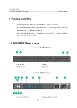
background image


GVT-052856-001-00 1.1 


QX-S6600 Series Ethernet Switches 

Installation Guide 


Summary of Contents for QX-S6632QP

Page 1: ...GVT 052856 001 00 1 1 QX S6600 Series Ethernet Switches Installation Guide ...

Page 2: ...Revision History Revision Date Reason for Change 1 1 2018 03 First Revision ...

Page 3: ...other trademarks that may be mentioned in this manual are the property of their respective owners Notice The information in this document is subject to change without notice Every effort has been made in the preparation of this document to ensure accuracy of the contents but all statements information and recommendations in this document do not constitute the warranty of any kind express or implie...

Page 4: ... This installation guide includes the following 11 sections Product overview The Product overview describes commands for QX S6600 Series panel views Preparing for installation The Preparing for installation describes commands for Safety recommendations Examining the installation site Temperature humidity etc Installing the switch The Installing the switch describes commands for Installing Mounting...

Page 5: ...m describes commands for QX S6600 Series cooling system Conventions This section describes the conventions used in this documentation set I Command conventions Convention Description Boldface Bold text represents commands and keywords that you enter literally as shown Italic Italic text represents arguments that you replace with actual values Square brackets enclose syntax choices keywords or argu...

Page 6: ...e A key at the same time KEY1 KEY2 Push in turn some KEYs of keyboard For example Alt A is push the Alt key then push the A key IV Mouse Operations Convention Description Click Push the button of the mouse one time quickly Usually push the left button Double Click Push the left button of the mouse two times quickly Drag Move the mouse while holding down the left button of the mouse V Symbols Conve...

Page 7: ...VI Configuration Example The configuration example of this document is an example Interface Number or the information of the display command etc may differ from your device ...

Page 8: ... 03 Installing the switch 04 Accessing the switch for the first time 05 Setting up an IRF fabric 06 Upgrading software 07 Maintenance and troubleshooting 08 Appendix A Technical specifications 09 Appendix B FRUs and compatibility matrixes 10 Appendix C Ports and LEDs 11 Appendix D Cooling system ...

Page 9: ...Installation Guide QX S6600 Series Ethernet Switches Contents i Contents 1 Product overview 1 1 QX S6648XP 6Q panel views 1 1 QX S6648XT 6Q panel views 1 3 QX S6632QP panel views 1 5 ...

Page 10: ... QX S6632QP switch the installing direction of QSFP module is same as the upper and lower ports About QX S6648XP 6Q switch the installing direction of QSFP module is different between the upper and lower ports QX S6648XP 6Q panel views QX S6648XP 6Q front panel 1 SFP port LED 2 SFP port 3 QSFP port LED 4 QSFP port QX S6648XP 6Q rear panel 1 System status LED Power 2 Management Ethernet RJ 45 port ...

Page 11: ...ories You can install one or two power modules for the switch as needed In Figure 1 2 two PSR450 12A N power modules are installed For more information about installing and removing the power module see Chapter 3 Installing removing a power module The QX S6648XP 6Q switch also comes with the fan tray slots empty You must install three fan trays for the QX S6648XP 6Q for adequate heat dissipation a...

Page 12: ... Fan tray slot 1 6 Fan tray slot 2 7 Fan tray slot 3 8 Fan tray slot 4 9 Fan tray slot 5 10 Power module slot 1 11 Power module slot 2 12 System status LED Power 13 LED for the management Ethernet RJ 45 port LINK ACT 14 Management Ethernet RJ 45 port 15 LED for the management Ethernet SFP port LINK ACT The QX S6648XT 6Q switch comes with the power module slots empty and the filler modules for the ...

Page 13: ...switch also comes with the fan tray slots empty You must install five fan trays for the QX S6648XT 6Q for adequate heat dissipation and their models must be the same In Figure 1 5 five LSPM5FANSB fan trays are installed For more information about installing and removing the fan tray see Chapter 3 Installing removing a fan tray QX S6648XT 6Q side panel 1 Primary grounding point 2 Auxiliary groundin...

Page 14: ...t ACT 10 Management Ethernet RJ 45 port 11 Grounding screw auxiliary grounding point 1 The QX S6632QP switch comes with the two power module slots empty and a filler pannel as an accessory You can install one or two power modules for the switch as needed In Figure 1 8 two LSVM3AC650 power modules are installed in the power module slots For more information about installing and removing the power m...

Page 15: ...itches 1 Product overview 1 6 installed in the fan tray slots For more information about installing and removing the fan tray see Chapter 3 Installing removing a fan tray QX S6632QP side panel 1 Primary grounding point 2 Auxiliary grounding point 1 ...

Page 16: ...Switches Contents i Contents 2 Preparing for installation 2 1 Safety recommendations 2 1 Connecting the RJ45 connector 2 2 Examining the installation site 2 2 Temperature humidity 2 3 Cleanness 2 3 EMI 2 4 Laser safety 2 4 Installation tools 2 5 ...

Page 17: ...efore moving the Switch unplug all power cords from the switch Do not place the switch near water or in a damp environment Prevent water or moisture from entering the switch chassis Do not place the switch on an unstable case or desk The switch might be severely damaged in case of a fall Ensure proper ventilation of the equipment room and keep the air inlet and outlet vents of the switch free of o...

Page 18: ... same care Connecting the RJ45 connector Examining the installation site The QX S6600 Series switches must be used indoors Mount your switch in a rack and make sure Adequate clearance is reserved at the air inlet and exhaust vents for ventilation The rack has a good ventilation system Identify the hot aisle and cold aisle at the installation site and make sure ambient air flows into the switch fro...

Page 19: ...emperature can accelerate the aging of insulation materials and significantly lower the reliability and lifespan of the switch For the temperature and humidity requirements of different switch models see Appendix A Technical specifications Cleanness Dust buildup on the chassis may result in electrostatic adsorption which causes poor contact of metal components and contact points especially when in...

Page 20: ...lease take the effective measures to reduce the intervention the power supply system exerts on the switch Keep the switch far away from high power radio launchers radars and equipment with high frequency or high current If AC power is used use a single phase three wire power receptacle with protection earth PE to filter interference from the power grid Keep the switch far away from radio transmitt...

Page 21: ... installation 2 5 WARNING Do not stare into any fiber port when the switch has power The laser light emitted from the optical fiber may hurt your eyes Installation tools Phillips screwdriver ESD preventive wrist strap NOTE All these installation tools are user supplied ...

Page 22: ... with a grounding strip 3 11 3 2 2 Grounding the switch by using the AC power cord 3 12 Installing removing a fan tray 3 14 3 3 1 Installing a fan tray 3 15 3 3 2 Removing a fan tray 3 16 Installing removing a power module 3 17 3 4 1 Installing a power module 3 18 3 4 2 Removing a power module 3 19 Connecting the power cord 3 21 3 5 1 Connecting the LSVM3AC650 PSR450 12A N power module 3 21 3 5 2 ...

Page 23: ...l switch shall not be guarantee applying If you tear off the tamper proof seal and open the chassis NEC shall not be liable for any consequence caused thereby Hardware installation flow Yes Connect the grounding cable Rack mount the switch Start Connect the power cords Verify the installation Power on the switch Operating properly Power off the switch Troubleshoot the switch No End Install fan tra...

Page 24: ... the QX S6648XT 6Q is a maximum of 657 5 mm so that the rack door can be closed easily The rack depth for the QX S6632QP is a maximum of 857 5 mm so that the rack door can be closed easily 3 1 2 Mounting bracket and rack mounting rail kits The QX S6600 Series Ethernet Switches come with a pair of mounting brackets see Figure 3 2 and a pair of chassis rails and a pair of slide rails see Figure 3 3 ...

Page 25: ... mounting brackets 3 1 4 Attaching the mounting brackets chassis rails and grounding cable to the chassis Each of the QX S6600 Series Ethernet Switches has one front mounting position near the network ports and one rear mounting position near the power modules The QX S6632QP provide three grounding points primary grounding point with a grounding sign auxiliary grounding point 1 and auxiliary groun...

Page 26: ...sition Mounting and grounding positions on the QX S6648XP 6Q 1 Power module side mounting position 2 Primary grounding point 3 Auxiliary grounding point 1 4 Port side mounting position Mounting and grounding positions on the QX S6648XT 6Q 1 Power module side mounting position 2 Primary grounding point 3 Auxiliary grounding point 1 4 Port side mounting position ...

Page 27: ...s with the rail mounting holes in the chassis If the mounting brackets are in the rear mounting position align the chassis rails with the screw holes at the front of the side panels see Figure 3 8 If the mounting brackets are in the front mounting position align the chassis rails with the screw holes at the rear of the side panels see Figure 3 9 4 Use M4 screws supplied with the switch to attach t...

Page 28: ...elf To connect the grounding cable to a chassis grounding point for example the primary grounding point 1 Choose a grounding point 2 Unpack the grounding cable and grounding screws You can use the cable and screws shipped with the switch only for connecting to the primary grounding point or auxiliary grounding point 1 3 Align the two hole grounding lug at one end of the cable with the grounding ho...

Page 29: ...uide QX S6600 Series Ethernet Switches 3 Installing the switch 3 7 Attaching the rear mounting brackets chassis rails grounding cable to the chassis Attaching the front mounting brackets chassis rails to the chassis ...

Page 30: ...e other slide rail to the rack post on the other side Keep the two slide rails at the same height so the slide rails can attach into the chassis rails Installing the slide rails 3 1 6 Mounting the switch in the rack This task requires two people To mount the switch in the rack 1 Wear an ESD preventive wrist strap and make sure it makes good skin contact and is well grounded 2 Verify that the mount...

Page 31: ... as shown in Figure Work with another person to slide the chassis rails along the slide rails until the mounting brackets are flush with the rack posts 6 Use screws user supplied to attach the mounting brackets to the rack as shown in Figure To secure the switch in the rack make sure the front ends of the slide rails reach out of the chassis rails Mounting the switch in the rack I ...

Page 32: ...wer input end of the switch has a noise filter whose central ground is directly connected to the chassis to form the chassis ground commonly known as PGND You must securely connect this chassis ground to the earth so the faradism and leakage electricity can be safely released to the earth to minimize EMI susceptibility of the switch You can ground a switch by using a grounding strip at the install...

Page 33: ...rod If a grounding strip is available at the installation site connect the grounding cable to the grounding strip To connect the grounding cable 1 Attach the two hole grounding lug at one end of the grounding cable to a grounding point on the switch chassis see Connecting the grounding cable to the chassis 2 Remove the hex nut of a grounding post on the grounding strip 3 Attach the ring terminal a...

Page 34: ... points To use auxiliary grounding point 2 on QX S6632QP prepare a grounding cable yourself The connection method is the same as connecting to the other two grounding points 3 2 2 Grounding the switch by using the AC power cord If the installation site has no grounding strips you can ground an AC powered switch through the protective earth PE wire of the power cord but must make sure The power cor...

Page 35: ...y other cable is used fire disasters or electric shock may be caused NOTE If the ground contact in the power outlet is not connected to the ground report the problem and reconstruct the grounding system Use the AC power cord which comply the standard of each country For the cables complying with our specifications see 9 1 Hot swappable power modules Table 3 1 and Table 3 2 ...

Page 36: ...effect use the grounding cable provided with the switch to connect to the grounding strip in the equipment room as long as possible Installing removing a fan tray CAUTION QX S6648XP 6Q requires three same direction air flow fan trays to function properly QX S6648XT 6Q requires five same direction air flow fan trays to function properly QX S6632QP requires two same direction air flow fan trays to f...

Page 37: ...the optional power modules and their specifications see Hot swappable fan trays CAUTION To prevent damage to the fan tray or the connectors on the backplane insert the fan tray gently If you encounter a hard resistance while inserting the fan tray pull out the fan tray and insert it again To install a fan tray 1 Wear an ESD preventive wrist strap and make sure it makes good skin contact and is wel...

Page 38: ...tray after the fans completely stop rotating To avoid an unbalanced fan causing loud noise do not touch the fans even if they are not rotating To remove a fan tray 1 Wear an ESD preventive wrist strap and make sure it makes good skin contact and is well grounded 2 Loosen the captive screw of the fan tray with a Philips screwdriver until it is fully disengaged from the switch chassis 3 Grasp the ha...

Page 39: ...lation and procedures in Figure 3 17 and Figure 3 18 to avoid any bodily injury or damage to the switch QX S6632QP come with the power module slots empty and filler panels for the power module slots as accessories QX S6648XP 6Q and QX S6648XT 6Q come with power module slot 1 empty and a filler panel installed in power module slot 2 For more information about the power modules available for the swi...

Page 40: ...e blank panel and the packaging box and packaging bag of the power module for future use The power module installation procedures are the same for the QX S6600 Series Ethernet Switches This section uses the QX S6632QP switch as an example To install a power module into the switch 1 Wear an ESD preventive wrist strap and make sure it makes good skin contact and is well grounded 2 Unpack the power m...

Page 41: ...operation of the switch If the switch has only one power module removing the power module powers off the switch The removal procedure is the same for the QX S6600 Series Ethernet Switches This section uses the QX S6632QP switch as an example To remove an LSVM3AC650 or LSVM3DC650 power module from the switch Firstly turn off the circuit breaker of the power cable 1 Wear an ESD preventive wrist stra...

Page 42: ...ule with one hand pivot the latch on the power module to the right with your thumb and pull the power module part way out of the slot as shown in Figure 3 22 4 Supporting the power module bottom with one hand slowly pull the power module out with the other hand 5 Put away the removed power module in an antistatic bag for future use Removing the DC power cord 1 Press the tabs on the power cord conn...

Page 43: ...ule slot to prevent dust from entering the chassis Connecting the power cord Warning When fixing power cable on equipment please can cut a power supply of equipment anytime in the state which reaches a plug of power cable and an outlet right now 3 5 1 Connecting the LSVM3AC650 PSR450 12A N power module 1 Insert the female connector of the AC power cord supplied with the power module into the power...

Page 44: ...s complying with our specifications see 9 1 Hot swappable power modules Table 3 1 and Table 3 2 Table 3 1 AC Input Power Specifications Input Voltage Current Max Phase Frequency Hz 100VAC 120VAC 220 230VAC 240VAC 10A 5A Single 50 60 Table 3 2 Power Cable Specifications Connector on the Device Side Cable Ratings Cable Length Plug Power Facility IEC 320 C13 125V 10A Comply the standard of each count...

Page 45: ...lug for connecting to the power module orient the plug with the power receptacle on the power module and insert the plug into the receptacle see Figure 3 24 The receptacle is foolproof If you cannot insert the plug into the receptacle re orient the plug rather than use excessive force to push it in 2 Use a cable tie to secure the power cord to the handle of the power module as shown in Figure 3 23...

Page 46: ...rt a SFP SFP QSFP module gently If you encounter a hard resistance while inserting a SFP SFP QSFP module pull out a SFP SFP QSFP module and insert it again WARNING Do not remove the dust proof cover before connecting a fiber optic cable Do not connect a fiber optic cable before inserting a SFP SFP QSFP module To install a SFP SFP QSFP module into the switch 1 Wear an ESD preventive wrist strap and...

Page 47: ...well grounded 2 Insert a UTP cable until you hear a click NOTE You must use Category5 cable or better including Cat5e and Cat6 The UTP cable is used for the connecting to 1 10G BASE T autosensing Ethernet port 10 100 1000Base T autosensing Ethernet port Management Ethernet port and 1000BASE T SFP 3 7 2 Connecting a fiber optic cable CAUTION Do not look in the port of each SFP SFP QSFP module Pleas...

Page 48: ...ing the installation After you complete the installation verify that There is enough space for heat dissipation around the switch and the rack is stable The grounding cable is securely connected The correct power source is used The power cords are properly connected All the interface cables are cabled indoors If any cable is routed outdoors verify that the socket strip with lightning protection an...

Page 49: ...ontents i Contents 4 Accessing the switch for the first time 4 1 Setting up the configuration environment 4 1 Connecting the console cable 4 1 4 2 1 Console cable 4 1 4 2 2 Connection procedure 4 2 Setting terminal parameters 4 2 Powering on the switch 4 5 ...

Page 50: ...use a console cable to connect a console terminal for example a PC to the console port on the switch Connecting the console port to a terminal Connecting the console cable 4 2 1 Console cable A console cable is an 8 core shielded cable with a crimped RJ 45 connector at one end for connecting to the console port of the switch and a DB 9 female connector at the other end for connecting to the serial...

Page 51: ...OTE Identify the mark on the console port and make sure you are connecting to the correct port The serial ports on PCs do not support hot swapping If the switch has been powered on connect the console cable to the PC before connecting to the switch and when you disconnect the cable first disconnect from the switch Setting terminal parameters To configure and manage the switch you must run a termin...

Page 52: ...unications HyperTerminal The Connection Description dialog box appears 2 Enter the name of the new connection in the Name field and click OK Connection description 3 Select the serial port to be used from the Connect using list and click OK Setting the serial port used by the HyperTerminal connection 4 Set Bits per second to 9600 Data bits to 8 Parity to None Stop bits to 1 and Flow control to Non...

Page 53: ...tallation Guide QX S6600 Series Ethernet Switches 4 Accessing the switch for the first time 4 4 Setting the serial port parameters 5 Select File Properties in the HyperTerminal window HyperTerminal window ...

Page 54: ...The input power voltage meets the requirement of the switch The console cable is properly connected The configuration terminal a PC for example has started and its serial port settings are consistent with the console port settings on the switch Power on the switch During the startup process you can access Boot ROM menus to perform tasks such as software upgrade and file management The Boot ROM int...

Page 55: ...ation commands and CLI see QX S6600 Series Ethernet Switches Configuration Guides and QX S6600 Series Ethernet Switches Command References NOTE If the device does not have a startup configuration the automatic configuration is started Please press Ctrl D to stop the automatic configuration because this device does not support the automatic configuration If the device version is Version 7 1 3 pleas...

Page 56: ...bric size and the installation site 5 2 5 2 2 Identifying the master switch and planning IRF member IDs 5 3 5 2 3 Planning IRF topology and connections 5 3 5 2 4 Identifying physical IRF ports on the member switches 5 5 5 2 5 Planning the cabling scheme 5 6 Configuring basic IRF settings 5 8 Connecting the physical IRF ports 5 8 Accessing the IRF fabric to verify the configuration 5 9 ...

Page 57: ...ttened network topology and high availability scalability and manageability To set up IRF links between two switches use SFP ports or QSFP ports IRF fabric setup flowchart IRF fabric setup flowchart Start Plan IRF fabric setup Install IRF member switches Power on the switches Configure basic IRF settings Connect the physical IRF ports End and power cords Connect the grounding cable IRF fabric is a...

Page 58: ...basic IRF settings See QX S6600 Series Ethernet Switches Configuration Guides 6 Connect the physical IRF ports Connect the physical IRF ports on switches Use SFP or QSFP transceiver modules and fibers for long distance connection Use SFP or QSFP cables for short distance connection All switches except the master switch automatically reboot and the IRF fabric is established Planning IRF fabric setu...

Page 59: ...ernet Switches Configuration Guides When an IRF fabric reboots its member devices might not all finish startup at the same time because of heterogeneity in device model If the member device that first finishes startup does not detect any member device within the IRF configuration detect time the member device becomes the master regardless of its priority Other member devices become the subordinate...

Page 60: ...provide 10 GE and 40 GE IRF connections through 1 10G Base T ports and QSFP ports respectively You can bind several 1 10G Base T or QSFP ports to an IRF port for increased bandwidth and availability The QX S6632QP can provide 40 GE IRF connections through QSFP ports You can bind several QSFP ports to an IRF port for increased bandwidth and availability NOTE Figure 5 3 shows the topologies of an IR...

Page 61: ...and connection scheme All the SFP and QSFP ports on the QX S6600 Series can be used for IRF connections Follow these guidelines when you identify SFP ports to be used for IRF connections On a QX S6648XP 6Q the SFP ports are grouped by port number in ascending order starting from one Every four SFP ports form one group On a QX S6648XT 6Q the 1 10 GE Ethernet ports are grouped by port number in asce...

Page 62: ...r QSFP transceiver modules and fibers to connect the IRF member switches For the QX S6632QP QSFP cables or QSFP transceiver modules and fibers to connect the IRF member switches If the IRF member switches are far away from one another choose the SFP QSFP transceiver modules with optical fibers If the IRF member switches are all in one equipment room choose twisted pair SFP QSFP cables For more inf...

Page 63: ... port1 IRF port1 1 2 3 4 IRF port1 IRF port2 II Connecting the IRF member switches in a ToR solution You can install IRF member switches in different racks side by side to deploy a top of rack ToR solution Figure 5 6 shows an example for connecting four top of rack IRF member switches by using QSFP cables and QSFP transceiver modules and optical fibers The topology is the same as Figure 5 5 ...

Page 64: ...rity than any other switch Bind physical ports to IRF port 1 on one switch and to IRF port 2 on the other switch You perform IRF port binding before or after connecting IRF physical ports depending on the software release Execute the display irf configuration command to verify the basic IRF settings For more information about configuring basic IRF settings see QX S6600 Series Ethernet Switches Con...

Page 65: ...s Ethernet Switches Configuration Guides 4 Check that you can manage all member switches as if they were one node 5 Display the running status of the IRF fabric by using the commands in Table 5 1 Table 5 1 Displaying and maintaining IRF configuration and running status Task Command Display information about the IRF fabric display irf Display all members IRF configurations that take effect at a reb...

Page 66: ...ages 6 9 Upgrading from the Boot menu 6 11 6 5 1 Prerequisites 6 12 6 5 2 Accessing the Boot menu 6 13 6 5 3 Using TFTP to upgrade software images through the management Ethernet port6 15 6 5 4 Using FTP to upgrade software through the management Ethernet port 6 18 6 5 5 Using XMODEM to upgrade software through the console port 6 21 Managing files from the Boot menu 6 28 6 6 1 Displaying all files...

Page 67: ...terface management configuration management and routing management The Comware software images that have been loaded are called current software images The Comware images specified to load at the next startup are called startup software images Boot image and system image are required for the system to work These images are released as a whole in one ipe package file Comware images If an ipe file i...

Page 68: ...m startup process Upgrade methods You can upgrade system software by using one of the following methods Upgrading method Software types Remarks Upgrading from the CLI Software images You must reboot the switch to complete the upgrade This method can interrupt ongoing network services ...

Page 69: ...hassis_software platform version_image type_release CAUTION Make sure that sufficient space is available for the upgrading software file If no sufficient space is available delete obsolete files The storage space needs the twice the size of ipe file because the ipe file is extracted to the boot image and system image Upgrading from the CLI This section uses a two member IRF fabric as an example to...

Page 70: ...nd in user view to identify the free storage space of each member switch 4 Identify the free Flash space of the master switch Switch dir Directory of flash 0 rw 41424 Jan 01 2011 02 23 44 startup mdb 1 rw 3792 Jan 01 2011 02 23 44 startup cfg 2 rw 23129088 Nov 25 2011 09 53 48 system bin 3 drw Jan 01 2011 00 00 07 seclog 4 drw Jan 01 2011 00 00 07 diagfile 5 drw Jan 02 2011 00 00 07 logfile 6 rw 8...

Page 71: ...deletes a file permanently and the action cannot be undone The delete file url command moves a file to the recycle bin and the file still occupies storage space To permanently delete the file from the recycle bin first perform the undelete command to restore the file and then perform the delete unreserved file url command 8 Delete obsolete files from the Flash memory of the master switch Switch de...

Page 72: ...ries does not come with these software programs II FTP download from a server You can use the switch as an FTP client to download files from an FTP server To download a file from an FTP server for example the server at 10 10 110 1 1 Run an FTP server program on the server configure an FTP username and password specify the working directory and copy the file for example newest ipe to the directory ...

Page 73: ...IRF fabric as an FTP server and upload files from a client to the IRF fabric To FTP upload a file from a client 1 On the IRF fabric 2 Enable FTP server Switch system view Switch ftp server enable 3 Add a local FTP user account set its password and access service type and assign it to the user role network admin for uploading file to the working directory of the server Switch local user abc Switch ...

Page 74: ...on the server specify the working directory and copy the file for example newest ipe to the directory 2 On the IRF fabric perform the tftp command in user view to download the file to the root directory in the Flash memory of the master switch Switch tftp 10 10 110 1 get newest ipe Total Received Xferd Average Speed Time Time Time Current Dload Upload Total Spent Left Speed 100 30 6M 0 30 6M 0 0 1...

Page 75: ...ware images at the next reboot on slot 1 2 Specify the upgrading image file used at next startup for the Standby switch and assign the M attribute to the boot and system images in the file As a result the Standby switch automatically copies the file to the root directory in its Flash memory CAUTION When a ipe file was designated as the image file used to start next time by the Standby switch devel...

Page 76: ... and automatically reboots with the new images to re join the IRF fabric In this upgrade process the function avoids the failure of assign all the Standby switches the same main software image file as the master switch causing an upgrade failure 4 Save the current configuration in any view to prevent data loss Switch save The current configuration will be written to the device Are you sure Y N y P...

Page 77: ...o make any choice in the required time the system upgrades the entire Boot ROM image Upgrading from the Boot menu You can upgrade the Boot ROM image and software images In this approach you must access the Boot menu of each member switch to upgrade their software one by one If you are upgrading software images for an IRF fabric using the CLI is a better choice The following sections describe the m...

Page 78: ...ts 1 Flow control None Emulation VT100 II TFTP FTP download To use TFTP or FTP Run a TFTP or FTP server program on the file server or the console terminal Copy the upgrade file to the file server Correctly set the working directory on the TFTP or FTP server Make sure that the file server and the switch can reach each other III Storage space Make sure that sufficient space is available for the upgr...

Page 79: ...Mac Address 94282EB7E6CF PEX mode is disabled Press Ctrl B to access EXTENDED BOOT MENU 0 Press Ctrl B at the prompt within one second to access the Boot menu If you fail to do that within the time limit the system starts decompressing files and you must restart the switch to access the Boot menu NOTE The system has two startup modes full startup and fast startup By default the system starts up in...

Page 80: ...covery 9 Set switch startup mode 0 Reboot Enter your choice 0 9 Table 6 1 Boot menu options Item Description 1 Download image to flash Download a software image file to the Flash memory 2 Select image to boot Select the main or backup startup software image to boot Select the main or backup configuration file to boot 3 Display all files in flash Display all files in the Flash memory 4 Delete file ...

Page 81: ...ter your Boot ROM password is lost and must contact your NEC agent for help 9 Set switch startup mode Set the startup mode of the switch to normal full mode or fast mode 0 Reboot Restart the switch Ctrl Z Access EXTENDED ASSISTANT MENU Access the EXTENDED ASSISTANT MENU Ctrl F Format file system Format file system Ctrl P Change authentication for console login Change authentication for console log...

Page 82: ...ample 192 168 0 2 Subnet Mask Subnet mask of the switch for example 255 255 255 0 Gateway IP Address IP address of the gateway in this example no gateway is required because the server and the switch are on the same subnet NOTE To use the default setting for a field press Enter without entering any value If the switch and the server are on different subnets you must specify a gateway address for t...

Page 83: ...ges are not available the switch tries to boot with the backup images An image with the none attribute is just stored in Flash memory for backup and you must change its attribute to make it usable at reboot If an image with the same attribute as the image you are loading is already in Flash memory the attribute of the old image changes to none after the new image becomes valid 6 Enter 0 in the Boo...

Page 84: ...col submenu 1 Set TFTP protocol parameters 2 Set FTP protocol parameters 3 Set XMODEM protocol parameters 0 Return to boot menu Enter your choice 0 3 2 Enter 2 to set the FTP parameters Load File name update ipe Server IP address 192 168 0 3 Local IP address 192 168 0 2 Subnet Mask 255 255 255 0 Gateway IP Address 0 0 0 0 FTP User Name switch FTP User Password 123 Table 6 3 FTP parameter descripti...

Page 85: ... without entering any value If the switch and the server are on different subnets you must specify a gateway address for the switch 3 Enter all required parameters and enter Y to confirm the settings The following prompt appears Are you sure to download file to flash Yes or No Y N Y 4 Enter Y to start downloading the image file To return to the Boot menu enter N Loading Done 5 Enter the M main B b...

Page 86: ...console login Ctrl R Download image to SDRAM and run Enter your choice 0 8 0 NOTE The switch always attempts to boot first with the main images and if the attempt fails for example because the main images not available the switch tries to boot with the backup images An image with the none attribute is just stored in Flash memory for backup and you must change its attribute to make it usable at reb...

Page 87: ...rn to boot menu Enter your choice 0 3 2 Enter 3 to set the XMODEM download baud rate Please select your download baudrate 1 9600 2 19200 3 38400 4 57600 5 115200 0 Return to boot menu Enter your choice 0 5 5 3 Select an appropriate download rate for example enter 5 to select 115200 bps Download baudrate is 115200 bps Please change the terminal s baudrate to 115200 bps and select XMODEM protocol Pr...

Page 88: ...Installation Guide QX S6600 Series Ethernet Switches 6 Upgrading software 6 22 Disconnecting the terminal from the switch 6 Select File Properties and in the Properties dialog box click Configure ...

Page 89: ...Installation Guide QX S6600 Series Ethernet Switches 6 Upgrading software 6 23 Properties dialog box 7 Select 115200 from the Bits per second list and click OK ...

Page 90: ...ll to reestablish the connection Reestablishing the connection 9 Press Enter The following prompt appears Are you sure to download file to flash Yes or No Y N Y 10 Enter Y to start downloading the file To return to the Boot menu enter N Now please start transfer file with XMODEM protocol If you want to exit Press Ctrl X ...

Page 91: ... CCCCCCCCCCCCCCCCCCCCCCCCC 11 Select Transfer Send File in the HyperTerminal window Transfer menu 12 In the dialog box that appears click Browse to select the source file and select Xmodem from the Protocol list File transmission dialog box 13 Click Send The following dialog box appears ...

Page 92: ...kup None m The boot bin image is self decompressing At the Load File name prompt enter a name for the Boot image to be saved to Flash memory Load File name default_file boot update bin Free space 470519808 bytes Writing flash Done The system update bin image is self decompressing At the Load File name prompt enter a name for the system image to be saved to Flash memory Load File name default_file ...

Page 93: ... image becomes valid 15 If the baud rate of the HyperTerminal is not 9600 bps restore it to 9600 bps If the baud rate is 9600 bps skip this step To access the switch through the console port after a reboot you must perform this step because the console port rate reverts to 9600 bps at a reboot 16 Press Enter to access the Boot menu EXTENDED BOOT MENU 1 Download image to flash 2 Select image to boo...

Page 94: ... space size EXTENDED BOOT MENU 1 Download image to flash 2 Select image to boot 3 Display all files in flash 4 Delete file from flash 5 Restore to factory default configuration 6 Enter BootRom upgrade menu 7 Skip current system configuration 8 Set switch startup mode 0 Reboot Ctrl Z Access EXTENDED ASSISTANT MENU Ctrl F Format file system Ctrl P Change authentication for console login Ctrl R Downl...

Page 95: ...kup attribute b with both main and backup attribute 6 6 2 Deleting files If storage space is insufficient delete obsolete files to free up storage space To delete files 1 Enter 4 in the Boot menu Deleting the file in flash File Number File Size bytes File Name 1 8177 flash testbackup cfg 2 23129088 flash system bin 3 8996864 flash boot bin 4 3678 flash startup cfg_backup 5 30033 flash default mdb ...

Page 96: ...age on the switch You can assign both the M and B attributes to one image If the M or B attribute you are assigning has been assigned to another image the assignment removes the attribute from that image If the removed attribute is the sole attribute of the image its attribute changes to N For example the system image system bin has the M attribute and the system image system update bin has the B ...

Page 97: ...on file enter 3 Enter 1 at the prompt to set the attribute of a software image in Version 7 1 3 To set the attribute of a configuration file enter 2 NOTE A setting method of the software image attribute was changed in Version 7 1 6 or later version When setting the Comware image attribute of the ipe file input 1 and specify Set image file When setting the Boot System image attribute of the ipe fil...

Page 98: ...te bin Please input the file number to change 3 5 Enter M or B to change its attribute to main or backup If you change its attribute to M the attribute of boot bin changes to none Please input the file attribute Main Backup None M This operation may take several minutes Please wait Next time boot update bin will become default boot file 6 At the prompt enter Y to reboot the switch with the new mai...

Page 99: ...g the console port for file transfer check the HyperTerminal settings including the baud rate and data bits for any wrong setting 5 Check the file transfer settings If XMODEM is used you must set the same baud rate for the terminal as for the console port If TFTP is used you must enter the same server IP addresses file name and working directory as set on the TFTP server If FTP is used you must en...

Page 100: ...ing 7 1 Password recovery 7 1 7 1 1 CLI login password loss 7 1 7 1 2 Super password loss 7 3 7 1 3 Way of load failure of the next startup configuration file 7 3 Power module failure 7 6 Fan failure 7 7 Configuration terminal problems 7 7 7 4 1 No terminal display 7 7 7 4 2 Garbled terminal display 7 8 ...

Page 101: ... 1 CLI login password loss When losing a CLI login password following procedure the device can be started without reading the current configuration file 1 Enter 7 at the prompt EXTENDED BOOT MENU 1 Download image to flash 2 Select image to boot 3 Display all files in flash 4 Delete file from flash 5 Restore to factory default configuration 6 Enter BootRom upgrade menu 7 Skip current system configu...

Page 102: ... console port without entering the password to check the configuration file for the user password EXTENDED BOOT MENU 1 Download image to flash 2 Select image to boot 3 Display all files in flash 4 Delete file from flash 5 Restore to factory default configuration 6 Enter BootRom upgrade menu 7 Skip current system configuration 8 Set switch startup mode 0 Reboot Ctrl Z Access EXTENDED ASSISTANT MENU...

Page 103: ...ord following procedure the device can be started without entering the password 1 Enter CTRL P at the Boot ROM menu Authentication is required for console login Are you sure you want to skip the authentication for console login Y N 2 Enter Y at the prompt Are you sure you want to skip the authentication for console login Y N Y Setting Done 3 Enter 0 at the prompt The switch reboots with empty conf...

Page 104: ...artup saved configuration file config2 cfg Next main startup saved configuration file config2 cfg Next backup startup saved configuration file NULL 3 To specify a next startup configuration file perform the following task in user view For example config1 cfg Switch startup saved configuration config1 cfg Please wait Done 4 When starting next time config1 cfg is read Uses the display startup comman...

Page 105: ... R Download image to SDRAM and run Enter your choice 0 8 3 Enter 7 at the prompt Enter your choice 0 8 7 4 When indicating The current setting is skipping configuration file when reboot please change the setting Enter your Y at the prompt The current setting is skipping configuration file when reboot Are you sure you want to run current configuration file when reboot Yes or No Y N Y Setting Done E...

Page 106: ...ou want to skip current configuration file when reboot Yes or No Y N N EXTENDED BOOT MENU 1 Download image to flash 2 Select image to boot 3 Display all files in flash 4 Delete file from flash 5 Restore to factory default configuration 6 Enter BootRom upgrade menu 7 Skip current system configuration 8 Set switch startup mode 0 Reboot Ctrl Z Access EXTENDED ASSISTANT MENU Ctrl F Format file system ...

Page 107: ... air flow fan trays to function properly Do not operate the system with one failed fan tray for more than 24 hours Do not remove the failed fan tray until you are ready for replacing it Do not operate the system without any fan tray for more than 2 minutes Do not operate the system outside of the temperature range 0 C to 45 C 32 F to 113 F degrees Failure to comply with these operating requirement...

Page 108: ...tch The console cable is properly connected The console cable has no problem and the terminal settings are correct 7 4 2 Garbled terminal display If terminal display is garbled verify that the following settings are configured for the terminal for example HyperTerminal Baud rate 9 600 Data bits 8 Parity none Stop bits 1 Flow control none Emulation VT100 ...

Page 109: ...Installation Guide QX S6600 Series Ethernet Switches Contents i Contents 8 Appendix A Technical specifications 8 1 Technical specifications 8 1 ...

Page 110: ...orts 1 SFP ports 48 N A N A QSFP ports 6 6 32 1 10GBase T autosensing Ethernet ports N A 48 N A Fan tray slots 3 5 2 Power module slots 2 AC input voltage Rated voltage 100 VAC to 240 VAC 50 or 60 Hz Max voltage 90 VAC to 264 VAC 47 to 63 Hz DC input voltage N A Rated voltage 60 VDC to 40 VDC Max voltage 72 VDC to 40 VDC Maximum power consumption AC 177W AC 280W AC 374 W DC 373 W Chassis leakage c...

Page 111: ...Ethernet Switches Contents i Contents 9 Appendix B FRUs and compatibility matrixes 9 1 Hot swappable power modules 9 1 9 1 1 Functions 9 1 9 1 2 Technical specifications 9 1 9 1 3 Appearance 9 3 9 1 4 LEDs 9 3 Hot swappable fan trays 9 4 ...

Page 112: ...d LSVM3DC650 can provide up to 650 W of output PSR450 12A N is a power module with AC input and DC output PSR450 12A N can provide up to 450 W of output LSVM3AC650 LSVM3DC650 and PSR450 12A N deliver the following features Feature Description Protection function Protection for over current input under voltage input over voltage output output short circuit and overheat Support for redundancy The po...

Page 113: ... 40 2 50 5 300 mm Operating temperature LSVM3AC650 5 C to 50 C LSVM3DC650 5 C to 45 C Relative humidity 5 to 95 Technical specifications of PSR450 12A N are showed in the following table Item Specifications Rated input voltage 100 VAC to 240 VAC 50 or 60 Hz Rated output voltage range 12 V 3 3V Maximum output current 37 5 A 12 V 2 A 3 3 V Maximum output power 450 W Power cable length 3 m Dimensions...

Page 114: ... Appearance LSVM3AC650 PSR450 12A N appearance 1 2 3 4 1 Latch 2 Status LED 3 AC input socket 4 Handle LSVM3DC650 appearance 1 2 3 4 1 Latch 2 Status LED 3 DC input socket 4 Handle 9 1 4 LEDs An LSVM3AC650 LSVM3DC650 has a status LED on its front panel The following table lists the LED status and description ...

Page 115: ... that has no power input blinks red Off The power modules have no power input PSR450 12A N has a status LED on its front panel The following table lists the LED status and description LED status Description Steady green The power module operates properly and is in the active state Blinking green The power module operates properly and is in the standby state Steady red The power module fails or ent...

Page 116: ... Front to back Fans draw air from the network port side to the power module side Input voltage 12 V Maximum power consumption 9 8 W LSWM3HFANSC for QX S6632QP Fans Two 40 40 56 mm fans Fan speed 21000 R P M Max airflow 70 CFM Airflow direction Back to front Fans blow air from the power module side to the network port side Input voltage 12 V Maximum power consumption 60 W LSWM3HFANSCB for QX S6632Q...

Page 117: ...0 1 10 1 3 USB port 10 3 10 1 4 SFP port 10 3 10 1 5 QSFP port 10 8 10 1 6 1 10G Base T autosensing Ethernet port 10 10 10 2 Twisted pair cable 10 11 10 3 LEDs 10 15 10 3 1 System status LED 10 15 10 3 2 SFP port LED 10 16 10 3 3 QSFP port LED 10 16 10 3 4 Management Ethernet port LEDs 10 16 10 3 5 1 10G Base T autosensing Ethernet port LEDs 10 17 10 3 6 Fan tray alarm LEDs 10 17 ...

Page 118: ... or remote through a pair of modems PC running terminal emulation program Provides connection to an ASCII terminal Provides connection to the serial port of a local PC running terminal emulation program 10 1 2 Management Ethernet port The QX S6648XP 6Q and QX S6648XT 6Q each have one management Ethernet RJ 45 port and one management Ethernet SFP port The QX S6632QP has one management Ethernet RJ 4...

Page 119: ...plex Transmission medium and max transmission distance See Table 10 4 Functions and services Software upgrade and network management Table 10 4 1000Mbps SFP Transceiver modules available for management Ethernet SFP ports Transceiver module Central wavelength Connector Fiber type and diameter 伝送距離 1000BASE SX SFP 850 nm LC 50 125 µm multi mode optical fiber 550 m 62 5 125 µm multi mode optical fibe...

Page 120: ...s You can use this USB port to access the file system on the Flash of the switch for example to upload or download application and configuration files NOTE Use option items of QX Switch series designation for the USB memory used by this product 10 1 4 SFP port QX S6648XP 6Q Series have fixed SFP ports You can plug the 1000Mbps SFP transceiver modules in Table 10 5 the 10Gbps SFP transceiver module...

Page 121: ... 1000BASE BX10 U SFP 1310 nm LC 9 125 µm single mode optical fiber 10 km 1000BASE BX10 D SFP 1490 nm LC 9 125 µm single mode optical fiber 10 km 1000BASE BX40 U SFP 1310 nm LC 9 125 µm single mode optical fiber 40 km 1000BASE BX40 D SFP 1490 nm LC 9 125 µm single mode optical fiber 40 km 1000BASE ZX LR SFP 1550 nm LC 9 125 µm single mode optical fiber 40 km 1000BASE ZX VR SFP 1550 nm LC 9 125 µm s...

Page 122: ...opper Cable DAC 3 m NOTE To guarantee the functionality of the SFP ports use only NEC SFP or SFP transceiver modules The SFP and SFP transceiver modules available for this switch series are subject to change over time For the most up to date list of SFP transceiver modules consult your NEC sales representative or technical support engineer A 40G QSFP 10G 4 SFP Copper cable can mount only the SFP c...

Page 123: ...Installation Guide QX S6600 Series Ethernet Switches 10 Appendix C Ports and LEDs 10 6 Figure 10 1 10G SFP Copper cable 1 2 1 Connector 2 Pull latch ...

Page 124: ... securing minimum bend radius of a cable there is damage of a cable or a possibility that performance deterioration forms Don t bend a cable below the minimum bend radius Figure 10 2 Minimum bend radius of 10G SFP Copper cable Figure 10 3 40G QSFP 10G 4 SFP Copper cable 1 2 3 4 1 QSFP connector 2 QSFP side pull latch 3 SFP side pull latch 4 SFP connector ...

Page 125: ...and 40G QSFP the right side of 40G QSFP 10G 4 SFP change copper wire cable 10 1 5 QSFP port QX S6600 Series provide QSFP ports You can plug the QSFP transceiver modules in Table 10 8 and the QSFP cables in Table 10 9 into the SFP ports as needed The QSFP cables available for the QX S6600 Series are 40 Gbps SFP Copper cables as shown in Figure 10 5 The SFP cables available for the QX S6600 Series a...

Page 126: ...3 m CAB 3M QSFP 4SFP 40G QSFP 10G 4 SFP Copper Cable DAC 3 m NOTE 40GBASE LR4 QSFP operates by after software including Version 7 1 12 To guarantee the functionality of the QSFP ports use only NEC QSFP transceiver modules and cables The QSFP transceiver modules and cables available for this switch series are subject to change over time For the most up to date list of SFP transceiver modules consul...

Page 127: ...XT 6Q has 1 10G Base T autosensing Ethernet ports Table 10 10 1 10G Base T autosensing Ethernet port specifications Item Specification Connector type RJ 45 Port transmission rate 1 10 Gbps full duplex MDI MDI X autosensing Transmission medium and max transmission distance 55 m 180 45 ft over category 6 unshielded twisted pair cable 100 m 328 08 ft over category 6 shielded twisted pair cable 100 m ...

Page 128: ...eet NOTE You must use Category5 cable or better including Cat5e Cat6 and Cat6A Twisted pair cable is used for the connecting to 10 100 1000Base T autosensing Ethernet port 1 10G Base T autosensing Ethernet port Management Ethernet port and 1000BASE T SFP I RJ45 connector Twisted pair cable uses RJ45 connector shown in Figure 10 6 Figure 10 6 RJ45 connector PIN 8 PIN 1 II Numbering of the pins Twis...

Page 129: ...rovides performance of up to 100 MHz and is suitable for 10 100 1000BASE T Ethernet Cat 6 The cable provides performance of up to 250 MHz and is suitable for 10 100 1000BASE T and 10GBASE T Cat 6A The cable provides performance of up to 500 MHz and is suitable for 1GBASE T and 10GBASE T 2 Pinouts When connecting a MDI port to an MDI X port a straight through cable is used when connecting two MDI p...

Page 130: ...te blue green white brown brown 1 2 3 4 5 6 7 8 Crossover Pinouts of 10 100 1000BASE T crossing cable is shown in Figure 10 8 The 10 100 1000BASE T crossing cable is different from a 100BASE TX crossing cable The pinout of a 100BASE TX crossing cable in one end is based on the 568B standard and other is based on the 568A standard By the way the pinout of a 10 100 1000BASE T crossing cable in one e...

Page 131: ...10 12 or MDI X Switch shown in Table 10 13 Table 10 12 Pin arrangement of MDI Pin 10Base T 100Base TX 1000Base T 10G Base T Signal Specification Signal Specification 1 Tx Transmission BIDA Two directions A 2 Tx Transmission BIDA Two directions A 3 Rx Receive BIDB Two directions B 4 Non data BIDC Two directions C 5 Non data BIDC Two directions C 6 Rx Receive BIDB Two directions B 7 Non data BIDD Tw...

Page 132: ... A 4 Non data BIDD Two directions D 5 Non data BIDD Two directions D 6 Tx Transmission BIDA Two directions A 7 Non data BIDC Two directions C 8 Non data BIDC Two directions C 10 3 LEDs 10 3 1 System status LED The system status LED shows the operating status of the switch Table 10 14 System status LED description LED mark Status Description SYS Steady green The switch is operating properly Flashin...

Page 133: ...r module or cable has been installed or no link is present on the port 10 3 3 QSFP port LED Each QSFP port has a status LED to show port operating status and activities Table 10 16 QSFP port LED description LED status Description Steady green A transceiver module or cable has been correctly installed The port has a link and is operating at 40 Gbps Flashing green The port is sending or receiving da...

Page 134: ...a 10 3 5 1 10G Base T autosensing Ethernet port LEDs Table 10 18 1 10G Base T autosensing Ethernet port LED description LED status Description Steady green The port has a link and is operating at 10 Gbps Flashing green The port is sending or receiving data at 10 Gbps Steady yellow The port has a link and is operating at 1 Gbps Flashing yellow The port is sending or receiving data at 1 Gbps Off No ...

Page 135: ...Installation Guide QX S6600 Series Ethernet Switches Contents i Contents 11 Appendix D Cooling system 11 1 QX S6600 Series cooling system 11 1 ...

Page 136: ... 6Q and QX S6648XT 6Q The fan trays in QX S6648XP 6Q and QX S6648XT 6Q must be the same type LSPM5FANSA or LSPM5FANSB The fan trays in QX S6632QP must be the same type LSWM3HFANSC or LSWM3HFANSCB When LSPM5FANSA LSWM3HFANSC fan trays are used cool air flows in through the air vents in the fan tray panel and the power module panels circulates through the chassis and the power modules and exhausts a...

Page 137: ...WM3HFANSC fan trays Airflow through the QX S6632QP chassis with LSWM3HFANSCB fan trays IMPORTANT The chassis and the power modules use separate air aisles Make sure both aisles are not blocked Please do not use LSPM5FANSA and LSPM5FANSB for QX S6632QP Please do not use LSWM3HFANSC and LSWM3HFANSCB for QX S6648XP 6Q and QX S6648XT 6Q ...

Reviews: