


AccuSync PV Series External Control Device Setup
SERVICE
Y
Pb
Pr
COMPONENT IN
(L) AUDIO (R)
S-VIDEO IN
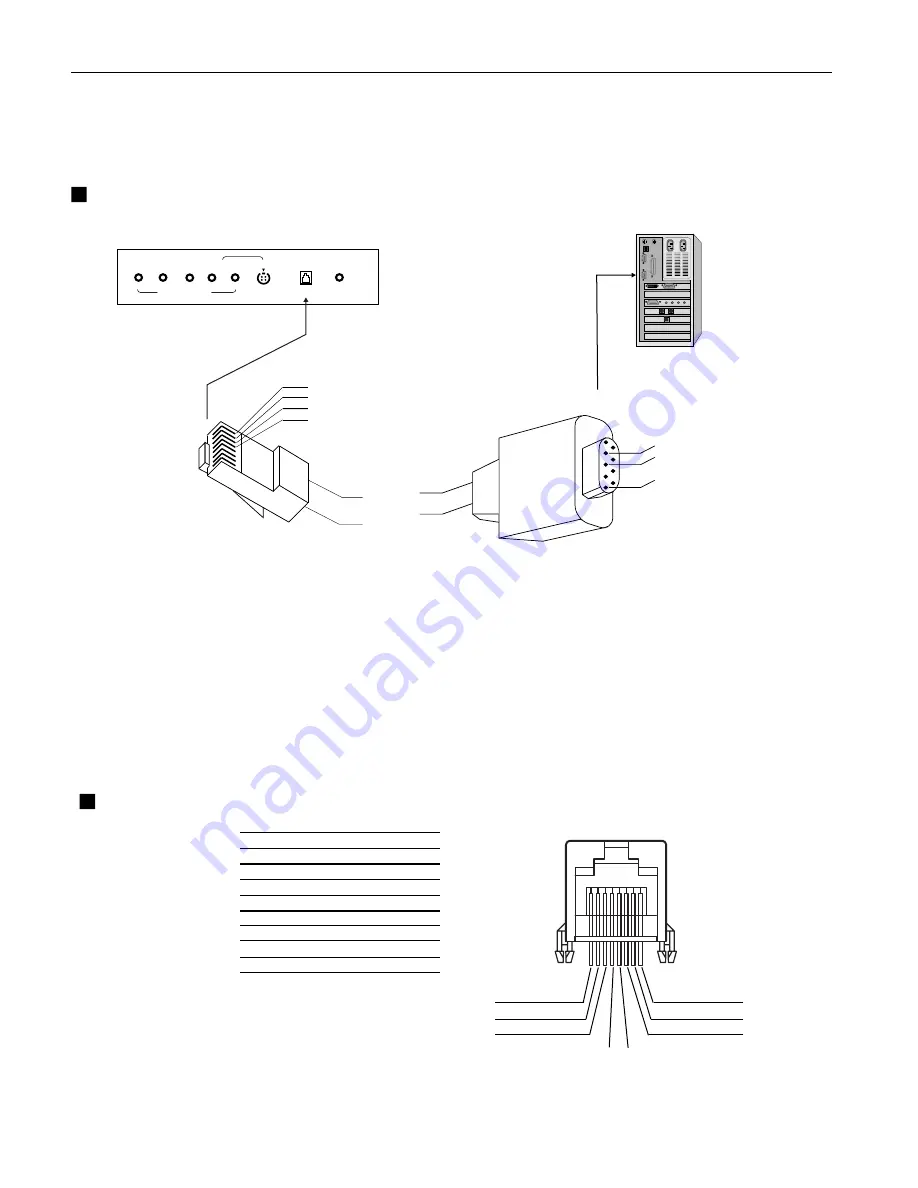
RS-232
< Back panel of the set >
1
2
3
8
7
6
4
5
Connect the RS-232 input jack to a control device (such as a
computer or an A/V control system) in order to control the set’s
functions externally.
RJ-45 8PIN CONNECTOR
Connect External Equipment
NO. PIN NAME
1
RXD(RECEIVE DATA)
2
TXD(TRANSMIT DATA)
3
4
GND
5
6
NO CONNCETION
7
NO CONNCETION
8
NO CONNCETION
Communication Parameters
• Baud rate : 9600bps (UART)
• Data length : 8bits
• Parity : None
• Stop bit : 1bit
• Communication code : HEX code
GND
NO CONNCETION
1
2
3
4
...
1
2
3, 4
Connect the serial port of the control device to the RS-232 jack on
the set.
RS-232 connection cables are not supplied with the Monitor.
The Monitor remote control and front panel controls (except main
power) will not be functional if the set is controlled by a PC
computer or other external device.
1


