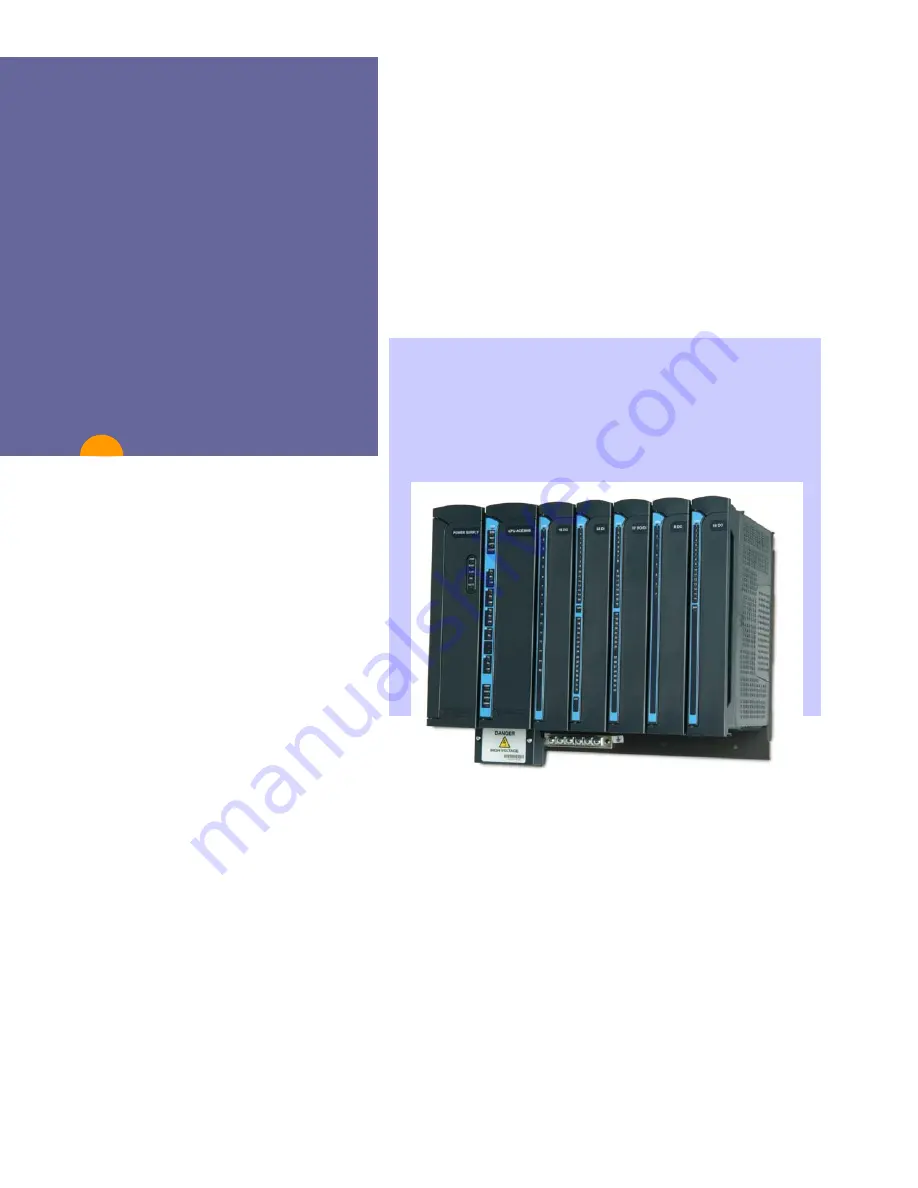
background image


Owner’s Manual


ACE3600 RTU 


6802979C35-L


ab 


MOTOROLA


, MOTO, MOTOROLA SOLUTIONS and the 

Stylized M Logo are


trademarks or registered trademarks of 

Motorola Trademark Holdings, LLC and are used under license. 
All other product or service names are the property of their 
respective owners. 

Copyright © 2014  All rights reserved 

Summary of Contents for ACE3600 RTU

Page 1: ...MOTOROLA SOLUTIONS and the Stylized M Logo are trademarks or registered trademarks of Motorola Trademark Holdings LLC and are used under license All other product or service names are the property of their respective owners Copyright 2014 All rights reserved ...

Page 2: ...ther directly or by implication estoppel or otherwise any license under the copyrights patents or patent applications of Motorola except for the normal non exclusive royalty free license to use that arises by operation of law in the sale of a product The ACE3600 RTU ACE IP Gateway software includes additional third party software components governed by specific licenses and under different copyrig...

Page 3: ...ND 2 20 CONNECTING AN RTU TO GROUND 2 21 CONNECTING THE RADIO 2 22 OPENING CLOSING THE HOUSING DOOR 2 22 INSTALLING ACCESSORY BOX INTERFACES 2 23 19 FRAME METAL BACK INSTALLATION COMBINATIONS 2 24 POWER SUPPLY MODULE AND BACKUP BATTERY 3 1 GENERAL DESCRIPTION MODULE OVERVIEW 3 1 REDUNDANT POWER SUPPLY 3 8 BATTERY CHARGER 3 8 CONNECTING THE POWER SUPPLY TO A POWER SOURCE 3 9 POWER SUPPLY DETAILED S...

Page 4: ... 5 CONNECTION CHARTS 7 6 I O CONNECTION DIAGRAM 7 7 HIGH VOLTAGE DI MODULE SPECIFICATIONS 7 8 DIGITAL OUTPUT DIGITAL INPUT FET MODULE 8 1 GENERAL DESCRIPTION 8 1 MODULE CONFIGURATION 8 2 MODULE STATUS AND DIAGNOSTICS 8 4 I O CIRCUIT DIAGRAM 8 5 MODULE BLOCK DIAGRAM 8 6 CONNECTION CHARTS 8 8 I O CONNECTION DIAGRAM 8 9 DO DI FET MODULE SPECIFICATIONS 8 10 DIGITAL OUTPUT RELAY MODULE 9 1 GENERAL DESC...

Page 5: ...ON 13 1 AO MODULE CONFIGURATION 13 3 MODULE STATUS AND DIAGNOSTICS 13 6 I O CIRCUIT DIAGRAM 13 7 MODULE BLOCK DIAGRAM 13 8 CONNECTION CHARTS 13 9 I I CONNECTION DIAGRAM 13 10 AO MODULE SPECIFICATIONS 13 11 MIXED I O MODULE 14 1 GENERAL DESCRIPTION 14 1 MIXED I O MODULE CONFIGURATION 14 3 MODULE STATUS AND DIAGNOSTICS 14 4 MODULE BLOCK DIAGRAM 14 5 CONNECTION CHARTS 14 6 MIXED I O MODULE SPECIFICAT...

Page 6: ...VERVIEW 19 1 MODULE STATUS AND DIAGNOSTICS 19 4 CONNECTING THE EXPANSION POWER SUPPLY TO THE MAIN FRAME POWER SUPPLY 19 4 CONNECTING THE EXPANSION POWER SUPPLY TO GROUND 19 4 EXPANSION POWER SUPPLY FUSES 19 5 EXPANSION POWER SUPPLY MODULE DETAILED SPECIFICATIONS 19 6 ACE IP GATEWAY MODULE 20 1 GENERAL DESCRIPTION 20 1 FRONT PANEL 20 3 ACE IP GATEWAY FIRMWARE AND OPERATION MODES 20 5 ACE IP GATEWAY...

Page 7: ... 29 4 REPLACING A PLUG IN SRAM MEMORY CARD IN THE CPU MODULE 29 4 REPLACING THE MOTHERBOARD 29 5 REPLACING THE FUSES ON THE POWER SUPPLY MODULE FOR AUX1 AUX2 OR I O EXPANSION 29 6 REPLACING THE BACKUP BATTERY ON THE RTU 29 6 INTERCONNECTION DIAGRAMS 29 6 APPENDIX A GENERAL SPECIFICATIONS A 1 SPECIFICATIONS A 1 APPENDIX B ENVIRONMENTAL PROTECTION B 1 DISPOSAL OF COMPONENTS B 1 APPENDIX C ACCESSORIE...

Page 8: ...ronmentally Preferred Product ESD Electrostatic Discharge EU European Union FCC Federal Communication Commission FEP Front End Processor MCP M MCP T or FIU FET Field Effect Transistor FPGA Field Programmable Gate Array FSK Phase Shift Keying FIU Field Interface Unit GND Ground GPRS General Packet Radio Service GPS Global Positioning Satellite GSM Global System for Mobile Communications GW ACE IP G...

Page 9: ... OVF Overflow PC Personal Computer PLC Programmable Logic Controller PPC Power PC PPH Pulse per Hour PPM Parts Per Million PPP Point to Point Protocol PPS Pulse per Second PSTN Public Switched Telephone Network RAM Random Access Memory RF Radio Frequency ROM Read Only Memory RST Reset RTS Request to Send RTU Remote Terminal Unit can be MOSCAD or MOSCAD L RX Receive SCADA Supervisory Control and Da...

Page 10: ...W Software TB Terminal Block TCP Transmission Control Protocol TDPSK Trunked Differential Phase Shift Keying TX Transmit UDF Underflow UDP User Datagram Protocol UHF Ultra High Frequency USB Universal Serial Bus VHF Very High Frequency WAN Wide Area Network WB Wire Break ...

Page 11: ...such as RTU configuration system application download monitoring etc Features of the ACE3600 The ACE3600 combines all the advantages of the legacy MOSCAD and MOSCAD L RTUs with those of modern hardware and software technologies Among these are A modern CPU platform with powerful microprocessor Real time operating system based on Wind Rivers VxWorks OS Enhanced communication and networking capabili...

Page 12: ...ions The following types of I O modules are available Digital Inputs DI including High Voltage Digital Outputs DO including High Voltage Analog Inputs AI Analog Outputs AO Mixed I O Mixed Analog Communication Interfaces The ACE3600 CPU includes the following serial ports Configurable RS232 or RS485 serial port Configurable RS232 with GPS receiver support for time sync Ethernet 10 100 Mb s ACE3600 ...

Page 13: ...ective housing which accommodates the frame and optional radios backup battery and communication interfaces suitable for outdoor installation The ACE3600 frame consists of the following elements Plastic slots which accommodate the power supply CPU and I O modules and backplane bus motherboard Mounting plate for attaching the plastic slots together and mounting the frame on a wall Backplane bus mot...

Page 14: ...ame metal back 2 I O slot frame Can be installed on a wall Power supply and CPU up to 2 I Os Can be ordered with small metal chassis 3 I O slot frame Can be installed on a wall Power supply and CPU up to 3 I Os Can be ordered with metal chassis or housing Can be ordered with 19 frame metal back 5 I O slot frame Can be installed on a wall Power supply and CPU up to 5 I Os Can be ordered with large ...

Page 15: ...ered with large metal chassis or housing Redundant CPU and power supply frame Can be installed on a wall in housing or in 19 rack enclosure 2 power supplies and 2 CPUs 4 I Os Can be ordered with large metal chassis housing or 19 frame metal back Small metal chassis Enables installation of radio backup battery and other accessories Can be installed on a wall or in housing Power supply and CPU up to...

Page 16: ...ead Acid backup battery and up to 2 accessory boxes For all possible combinations see 19 Metal Back Installation Combinations in the Installation chapter below Small NEMA 4X IP66 housing Enables installation of radio backup battery and other accessories Can be installed on a wall Power supply and CPU up to 3 I Os 1 mobile portable radio 1 accessory box 6 5 Ah Lead Acid backup battery Large metal N...

Page 17: ...ery chapter CPU module Stores and runs the user application program stores data collected by the I O modules and communicates with the control center RTUs and other devices via the communication ports See CPU Module chapter CPU plug in port Enables adding various communication ports to the CPU modules See CPU Module chapter CPU plug in SRAM Provides static RAM See CPU Module chapter I O module Mat...

Page 18: ... up to thirteen expansion frames to the main frame CPU See Expansion LAN Switch chapter ACE IP Gateway module Serves as a front end unit between ACE3600 MOSCAD RTUs and control center SCADA clients using TCP IP protocol See ACE IP Gateway Module chapter TB holder kit Holds Module TBs See I O Modules chapter Cable with TB holder A cable to connect signals to the I O modules See I O Modules chapter ...

Page 19: ...uch as RTU configuration system application download monitoring etc See the ACE3600 STS User Guide Ethernet cable Enables the following connections 1 CPU to LAN switch 2 LAN switch to expansion frame 3 LAN switch to LAN switch See Expansion Module chapter Ethernet cross cable Enables the following connections 1 A single I O expansion frame directly to the RTU main frame 2 PC STS directly to one of...

Page 20: ...cription 1 10 Product Safety and RF Exposure Before using an ACE3600 RTU model with a radio installed read the operating instructions and RF exposure booklet for the specific radio contained in the product ...

Page 21: ...nicians must be specifically qualified to handle high voltage This unit is intended for installation in a Restricted Access Location for service personnel only Connection of this equipment to an IT earthing system is permitted for the IT power system of Norway only INSTALLATION CODES This device must be installed according to the latest version of the country s national electrical codes For North ...

Page 22: ...a Wall Before drilling holes for mounting the frame make sure there are no electrical wires installed inside the wall at the holes location Four holes are provided one in each corner of the RTU frame for wall mounting the RTU Figure 2 1 Figure 2 2 and Figure 2 3 show the dimensions of the various frames metal chassis and the distances between the holes For convenient installation of the ACE3600 RT...

Page 23: ...ize as the 7 I O frame The following screw mount installation procedure should be used to install all ACE3600 frames with or without a metal chassis on a wall except the 8 I O 19 frame For the 8 I O frame see Installing the ACE3600 in a 19 Rack and Mounting the ACE3600 8 I O Frame on a Wall below Procedure 2 1 How to Mount the RTU Frame on a Wall 1 Drill four holes in the wall at the horizontal an...

Page 24: ...9 rack installation are not provided with the RTU and should be ordered separately Procedure 2 2 How to Mount the RTU in a 19 Rack Unit 1 Using three M4 screws supplied with kit FHN7420A attach the metal bracket p n 07013005001 from kit FHN7420A to the side of the 19 frame metal back according to the desired depth of the unit on the rack Repeat with the second bracket on the other side of the 19 f...

Page 25: ...th the two screws on the rack metal uprights and hang the frame on the rack metal uprights See Figure 2 6 Tighten the two screws to the uprights 4 To reinforce the installation add three more M5 screws not supplied through the remaining three holes on the metal bracket into the upright of the 19 rack unit Repeat on the opposite upright See Figure 2 6 ...

Page 26: ...the ACE3600 8 I O 19 frame in a 19 rack for RTUs ordered before October 2010 Note The brackets for 19 rack installation are not provided with the RTU and should be ordered separately Procedure 2 3 How to Mount the RTU in a 19 Rack Unit 1 Press the small metal bracket into the slot of the larger bracket See Figure 2 7 2 Secure the two brackets together with two M5 screws supplied according to the d...

Page 27: ...pplied two screws attach the combined brackets to the metal upright of a 19 rack unit See Figure 2 7 Repeat on other side Bracket Groove Small Bracket Large Bracket Metal Upright Figure 2 7 Installation of Brackets for 19 Rack Units ...

Page 28: ...w 6 From the standard rack unit remove the two modules from the leftmost slots and the two modules from the rightmost slots For the 19 accessories metal chassis no accessories need to be removed See Figure 2 9 7 Using two supplied M5 X6 screws and a 16 cm 6 3 long screwdriver from inside the slot secure the 19 frame metal back to the small bracket Repeat on the second side See Figure 2 8 8 Replace...

Page 29: ...rame on a Wall 465 9 mm 235 mm 146 1 mm 88 9 mm Additional screws for extra fortification Figure 2 10 8 I O Frame 19 Metal Back Installation Dimensions The following screw mount installation procedure should be used to install the ACE3600 8 I O 19 frame on the wall The redundant CPU and power supply frame on a 19 frame metal back can also be installed in a 19 rack unit ...

Page 30: ...re 2 10 3 Using two M5 screws not supplied secure the rectangular wall mounting bracket 07013022001 from kit FHN7419A to the wall as shown in Figure 2 11 Repeat for the second bracket Figure 2 11 19 Frame Metal Back Bracket Installation 4 Fit the metal frame in between the two brackets lining up the holes on the sides See Figure 2 12 5 Using three supplied M4 screws secure the left bracket to the ...

Page 31: ...RTU 19 Frame Metal Back on a Wall The following installation procedure should be used to install the 8 I O 19 frame on a wall using the special wall mount brackets provided with the RTU 1 Remove the CPU Power Supply and I O modules from the RTU frame 2 Drill four holes into the wall at the horizontal and vertical distances shown in Figure 2 13 3 Using two supplied screws secure the rectangular wal...

Page 32: ... Chassis Installation Mounting the ACE3600 NEMA 4 Housing on a Wall The following screw mount installation procedure should be used to install ACE3600 frames in NEMA 4 housing on a wall For convenient installation of the ACE3600 RTU with the NEMA 4 housing allow an additional 6 cm 2 4 in W H and 7 cm 2 75 in D around the housing Four mounting brackets are provided one in each corner of the RTU for...

Page 33: ...n the wall at the horizontal and vertical distances shown in Figure 2 15 for the large housing and in Figure 2 16 for the small housing 2 Using the brackets and the screws supplied in the plastic bag fasten the mounting brackets either horizontally or vertically onto the four back corners of the housing See Figure 2 17 3 Mount the RTU onto the wall and secure with M4 screws not supplied with head ...

Page 34: ... authorized service personnel All power and ground connections must be in accordance with local standards and laws Per UL 60950 EN 60950 for all I O modules connections the maximum voltage should not exceed 60V DC or 30 V AC unless it is specifically written otherwise To maintain Overvoltage Installation Category II install a suitable surge suppressor device in the branch circuit to limit expected...

Page 35: ...oints Anchor point 1 for all units is inside the power junction box See Figure 2 18 below Anchor point 2 for the basic model No I O Slots Frame is located on the right of the power junction box See Figure 2 18 below Anchor point 2 for all units with housing other than No I O Slots is in the housing power cable gland See Figure 2 22 below Anchor point 2 for all other units without housing other tha...

Page 36: ...ews inside the power junction box 2 Thread the user s main power cable through the two supplied clamps 3 Attach the wires of the user cable according to the labels 0 for AC and for DC For the No I O Frame connect the ground cable to the lower wire terminals third pair See Figure 2 20 and Figure 2 21 Power Supply Cable Inlet User Power Cable Wire Terminals Anchor Point 1 Junction Box Ground Cables ...

Page 37: ...p or on the bottom of the plastic to the right of the junction box in case of the No I O Slots frame 7 Replace the junction box cover over the junction box 8 Secure the junction box cover with two saved screws 9 For all installations except the No I O frame loosen the two screws on the grounding strip at the bottom of the metal chassis housing and connect the ground cable to the protective ground ...

Page 38: ...able gland cover from below through the cable gland and into the housing See Figure 2 22 Cable Gland Grommet RTU Housing Nut Cable Gland Cover Power Cable Figure 2 22 RTU in NEMA 4 Housing Cable Gland Anchor Point 2 5 Attach the wires of the user cable according to labels 0 for AC and for DC See Figure 2 20 and Figure 2 21 For the No I O frame connect the ground cable to the lower wire terminals t...

Page 39: ...e power as follows Procedure 2 9 How to Connect the Expansion Power Supply to the Main Frame Power Supply 1 Using a DC power cable FKN8559A 3002360C26 connect the Rack Exp connector from the power supply on the main frame to the Power In connector on the Expansion power supply 2 If the RTU includes more than one Expansion frame use a DC power cable FKN8559A 3002360C26 to connect the Expansion Powe...

Page 40: ...inal voltage level before connecting it If the battery voltage is less than 12 5V DC DO NOT use the battery and replace it with a charged battery that measures at least 12 5V DC 3 If the battery passes a visual inspection and the terminal voltage is correct plug the battery cable FKN8376A 3089927V10 into the Battery In Out connector on the power supply module 4 Fully charge the battery prior to in...

Page 41: ...nding strip of each frame must be connected to the grounding point of the cabinet or 19 rack Figure 2 23 below depicts the ground connections of an RTU with a single expansion frame and Figure 2 24 depicts the ground connections of an RTU with multiple expansion frames Crossed LAN Cable I O Frame DC Cable Main Frame Grounding Wire Protective Ground Figure 2 23 Ground Connections of an RTU with a S...

Page 42: ...o open a large RTU housing equipped with two door latches turn both latches clockwise The door will open To open a large RTU housing equipped with the padlock accessory and a latch remove the user supplied padlock if one exists and turn the padlock accessory and latch clockwise The door will open 2 To close a small RTU housing equipped with a door latch turn the latch counterclockwise and push the...

Page 43: ...assis small large metal chassis or small large NEMA housing Procedure 2 13 How to Install the Accessory Box Interface on the Metal Chassis 1 To connect the accessory box interface to the metal chassis place the box on the metal plate and click the two pegs on the back of the accessory box into the desired holes on the metal chassis See Figure 2 27 Note This figure is for illustration purposes only...

Page 44: ...ull out the unit 19 Frame Metal Back Installation Combinations The 19 frame metal back can be ordered with a variety of frames modules and accessories e g battery radio accessory box In certain cases choosing a certain accessory reduces the other options For example the portable radio is installed on the 19 frame metal back with the No I O Frame in place of one accessory box Likewise a battery is ...

Page 45: ...Installation 2 25 ...

Page 46: ...Installation 2 26 Figure 2 28 19 Frame Metal Back Installation Combinations ...

Page 47: ... low tier On Off button on the front panel Controlled auxiliary voltage outputs Heat convection cooling no need for fans Short protection outputs Over heating protection Status LEDs in the front panel Power supply located on the leftmost slot of the frame to the left of the CPU In a frame with both redundant CPUs and redundant power supplies the third slot from the left between the primary CPU and...

Page 48: ...ower on power return Temperature compensated charging Over charging protection Over discharge protection Battery test and diagnostics including battery controlled discharge Battery charging current control Characteristics of the DC power supply low tier Two auxiliary voltage outputs Short circuit protection outputs PS located on the leftmost slot of the frame Overvoltage protection for CPU and I O...

Page 49: ... VDC AUX 1A ON OFF Power Supply DC Power Supply Low Tier Figure 3 1 ACE3600 Power Supply General View Note An additional power supply module for use with I O expansion frames is described in the Expansion Power Supply Module chapter below METAL PARTS OF THE POWER SUPPLY MAY BE VERY HOT After removing the power supply module allow the metal parts to cool down before servicing the unit ...

Page 50: ...re disabled Press the button for at least two seconds to change states In power supply modules equipped with a battery charger if the power supply module is in the OFF state and the RTU main power is connected the Battery In Out is not disabled to ensure battery charging If the RTU main power AC DC is disconnected and the power supply module is shut off there is still some current draw from the ba...

Page 51: ... by default with 13 8V DC Do NOT plug in a radio which requires less voltage or the radio may be damaged Auxiliary Output 2A DC Power Output Selectable programmable 3 3 to 9V DC or 13 8V DC 5 20 C User controlled power output Short protected This output is used for powering radios modems etc The output voltage can be set by the user using the STS site configuration The output can be switched ON OF...

Page 52: ... setting this control see the Module Configuration section of the DO Relay Module chapter The power supplies on I O expansion frames can be attached via DC cable to the power supply on the previous I O expansion frame in a daisy chain manner or directly to the main power supply In this case the 12V DO control on the main power supply can control all DO EE relays in the entire RTU that were configu...

Page 53: ...e RTU it is recommended to have a single on off switch to control all power supplies simultaneously Battery In Out only in power supply with charger Battery charger output when the main power exists Backup power input from battery when the main power fails The charging voltage level is controlled by the battery charger and is a function of the temperature Temperature Sensor Sensor for battery temp...

Page 54: ...ve the power supply module first unplug the power input cable LEDs The front panel of the power supply module not including the DC power supply low tier includes five indication LEDs LED Name Description Status PWR Power LED Indicates the existence of AC or DC main power in the Main Power input When the power supply module is in the ON state LED ON Green When the power supply module is in the OFF ...

Page 55: ...erformed LED ON Green Blinking Battery tests are performed using the STS Hardware Test function or the user application program Redundant Power Supply Redundant power supplies are used to ensure a continuous supply of the required RTU voltages in the event that one power supply fails For details on the redundant power supply see Appendix E CPU and Power Supply Redundancy below Battery Charger Powe...

Page 56: ...el test once per day The capacity test lowers the main DC to a safety net level 12V so that the battery will be activated The battery is heavily loaded for 45 seconds the power supply LED blinks green and the battery capacity is measured If the capacity is below the manufacturer recommended level the battery should be replaced with a new one See Replacing the Backup Battery below Note that the cap...

Page 57: ... connected to a DC power source only The expansion power supply module is connected to another ACE36000 power supply using a DC power cable FKN8559A 3002360C26 For instructions on connecting the power supply to a power source see the Power and Ground Connections section of the Installation chapter above All power and ground connections must be in accordance with local standards and laws ...

Page 58: ...10 max 2 5A on off default controlled by user program Note max 8 A total current consumption from all outputs No Load Power Consumption Max 50 mA Diagnostic LEDs Status LED for input voltage AUX1 and AUX2 outputs 12V control for DO modules Input Protection Internal line fuse replaceable Output Protection AUX2A B short circuit automatic recovery on 3 3 5 7 5 9 V Dimensions 56 mm W x 225 mm H x 180 ...

Page 59: ...rger Automatic charging of 6 5 or 10 Ah backup battery battery temperature sensing overcharging protection battery capacity test and diagnostics automatic battery switch over Diagnostic LEDs Status LED for input voltage AUX1 and AUX2 outputs 12 V Control DO for DO modules and battery No Load Power Consumption Max 250 mA Efficiency 80 typical 76 with full load Inrush Current 10 A maximum for 2 mSec...

Page 60: ...ger Automatic charging of 6 5 or 10 Ah backup battery battery temperature sensing overcharging protection battery capacity test and diagnostics automatic battery switch over Diagnostic LEDs Status LED for input voltage AUX1 and AUX2 outputs 12V Control for DO modules and battery No Load Power Consumption 130 mA 220 V AC Efficiency 80 typical 230 V AC 76 typical 115 V AC full load Inrush Current 25...

Page 61: ...if connected to a power supply charger the battery may produce excessive internal heat and therefore deform and or leak The batteries are shipped disconnected from the power supply charger To ensure that there are no battery problems on your ACE3600 project each Lead Acid battery MUST be fully charged and checked before connecting it to the ACE3600 power supply charger To verify that the battery i...

Page 62: ... battery before recharging is 12 42 V which represents remaining capacity of approximately 30 Therefore it is recommended to perform a full charging cycle every few months depending upon the storage temperature of the battery Please refer to Table 3 1 to determine the suggested maximal period between recharge cycles that suits the actual storage conditions Improper storage may cause deep discharge...

Page 63: ...ry leaks and the liquid inside touch the skin or clothing immediately wash it off with plenty of clean water If the liquid splashes into eyes immediately flush the eyes with plenty of clean water and consult a doctor Sulfuric acid in the eyes may cause loss of eyesight and acid on the skin will cause burns Procedure 3 1 How to Replace the Lead Acid Backup Battery To replace the Lead Acid backup ba...

Page 64: ... battery terminal voltage level before connecting it If the battery voltage is less than 12 42V DC DO NOT use the battery and replace it 6 If the replacement battery passed the visual inspection and the terminal voltage is satisfactory put the battery into place on the RTU and screw in the battery holders 7 Connect the battery cable to the battery terminals in the correct polarity 8 Connect the ba...

Page 65: ... must be plugged into the wide slot to the right of the Power Supply module Inserting the module in the wrong slot will not cause any damage to the CPU For information on the location and arrangement of CPUs in the redundant CPU and power supply frame see Appendix E CPU and Power Supply Redundancy below Figure 4 1 provides a general view of the ACE3600 CPU Models 3610 PWR ERR RST APPL CONF Tx Rx C...

Page 66: ...Rx Tx Rx CM LNK ERR RST APPL CONF P1 Tx S1 S2 E1 E2 P2 H1 D1 Figure 4 2 ACE3600 CPU Models 3610 3640 3680 Front Panel Front Panel Communication Ports The CPU module includes several communication ports On Board ports USB Host 1 2 HU1 HU2 USB Type A host full speed ports for MDLC over IP communication via the MotoTrbo digital mode radio system up to two radios attached to two USB host ports at one ...

Page 67: ...eds of ACE3600 and peer Ethernet ports will match whether or not the peer supports Auto Negotiation If the peer supports Auto Negotiation the duplex of ACE3600 and the peer Ethernet ports also match It is recommended to configure the Ethernet port of the device connected to the ACE3600 Ethernet port e g switch etc to Auto Negotiation mode This will guarantee a full match of speed and duplex betwee...

Page 68: ...t status The user LEDs can be used by the user application program Note that during startup or failure the communication and user LEDs are used to indicate various situations Table 4 4 details the LEDs functionality CPU Memory The ACE3600 CPU includes Flash SDRAM and optional SRAM Plug in memory The Flash stores the firmware the user application program and the user data The SDRAM memory stores th...

Page 69: ... battery When the SRAM option is not used the Lithium battery will keep the Real Time Clock running for a longer period of time CPU with Security In an ACE3600 system with security the CPU 3680 has a dedicated security hardware repository Backup power and data retention for this repository is also provided by the rechargeable lithium battery For more information on the security repository see the ...

Page 70: ... A failure message will appear in the STS Downloader screen For information on using the Safe Firmware Download feature see the Safe Firmware Download section of the ACE3600 STS Advanced Features manual Restart after Configuration Download The RTU will restart after downloading a site configuration For information on downloading to the RTU see the Operation chapter of the ACE3600 STS User Guide If...

Page 71: ...er modes of CPU operation The existence of CPU warnings and errors are indicated in the ERR LED on the front panel of the module Green indicates a message orange indicates a warning and red indicates an error The CPU error logger information can be retrieved using the STS Error Logger utility For more details see the Error Logger section of the ACE3600 STS User Guide CPU Serial Number Each CPU has...

Page 72: ...ove the cover from the desired opening on the front panel 3 Connect two supporting pins with screws to the plug in port 4 Place the plug in board with the RJ 45 connector facing the panel Carefully insert the plug in board connector into the appropriate connector on the CPU board For Ethernet 10 100 MB use the J14 connector on the CPU Plug in 1 only For all other plug in ports use the J5 Plug in 1...

Page 73: ...y in the ACE3600 CPU module Figure 4 4 SRAM Expansion in CPU Module Procedure 4 3 describes how to connect a plug in SRAM memory card to the CPU Procedure 4 2 How to Connect a Plug in SRAM Memory Card to the CPU 1 Remove the CPU module from the RTU 2 Remove the cover from the connector marked P12 on the CPU board 3 Place the plug in SRAM memory card with the connector facing the panel Carefully in...

Page 74: ...B1 is released during this time the restart will not be performed At the long beep release PB1 and the RTU will restart and the buzzer will buzz Turn LEDs ON During run time press PB1 for one second Those LEDs which are currently active will be turned on for a period of time configured in the RTU configuration using the STS RAM Test During startup press PB1 A detailed memory test of SDRAM and SRAM...

Page 75: ...he RTU will start up in diagnostic mode Communication with the RTU is for diagnostic purposes only Error Logger SW Diagnostics You cannot download to the RTU and no application will run If the bootstrap fails the four indicator LEDs see LEDs Location in Table 4 3 will display the failure error in binary code as described in Table 4 3 Table 4 3 ACE3600 Failure Error Code Display on LEDs LEDs Locati...

Page 76: ...ged Note In systems with I O expansion the ERR LED can indicate an error in either the main or expansion frame RST Reset LED Bicolor LED Red Green Green On startup OFF Successful power up or restart Red Power up or restart failed APPL Application LED Bicolor LED Red Green OFF No user application program in the Flash memory Green User application program is running Orange User application program w...

Page 77: ...erial Port 1 TX transmit Green LED ON Transmitting Data SI1 RX Serial Port 1 RX receive Green LED ON Receiving Data SI1 CM Serial Port 1 CM channel monitor Green LED ON Channel Monitor is ON S2 TX Serial Port 2 TX transmit Green LED ON Transmitting Data S2 RX Serial Port 2 RX receive Green LED ON Receiving Data S2 CM Serial Port 2 CM channel monitor Green LED ON Channel Monitor is ON E1 LNK Ethern...

Page 78: ... and data is being received OFF The system does not include Redundancy PI2 TX Plug in Port 2 TX transmit Green LED ON Transmitting Data PI2 RX Plug in Port 2 RX receive Green LED ON Receiving Data PI2 CM Plug in Port 2 CM channel monitor Green LED ON Channel Busy if port is in use by radio RS485 or RS232 Network Connected if an IP plug in is used D1 RX USB Device Port RX receive ON Receiving Data ...

Page 79: ...receiver interface Ethernet Port 1 10 100 Mb s on CPU 3640 only Plug In Port 1 Supports the following plug in ports Radio Modem DPSK 1 2 kb s FSK 1 2 1 8 2 4 kb s DFM 2 4 3 6 4 8 kb s RS232 Sync Asynch Full Flow Control up to 230 4 kb s GPS receiver interface RS485 multi drop 2 Wire up to 230 4 kb s Ethernet 10 100 Mb s Plug In Port 2 Supports the following plug in ports Radio Modem DPSK 1 2 kb s ...

Page 80: ... GPS receiver interface RS485 multi drop 2 Wire up to 230 4 kb s Serial Port 2 RS232 Asynch Full Flow Control up to 230 4 kb s GPS receiver interface Ethernet Port 1 Ethernet 10 100 Mb s USB Device Port 1 USB device port Type B connector Internal Ethernet Port 1 Internal 100 Mb s Ethernet port for redundant CPU interconnection Plug In Port 1 Supports the following plug in ports Radio Modem DPSK 1 ...

Page 81: ...le 4 17 Operating Voltage 10 8 16 V DC from the motherboard connector Dimensions 56 mm W x 225 mm H x 180 mm D 2 2 W x 8 7 H x 7 1 D Weight Approx 0 38 Kg 0 84 Lb Specifications subject to change without notice ...

Page 82: ...wap Figure 5 1 provides a general view of an ACE3600 I O module ERR OF UF OF UF OF UF OF UF OF UF OF UF OF UF OF UF 24V 1 2 3 4 5 6 7 8 ERR OF UF OF UF OF UF OF UF OF UF OF UF OF UF OF UF 24V OF UF OF UF OF UF OF UF OF UF OF UF OF UF OF UF 1 2 3 4 5 6 7 8 9 10 11 12 13 14 15 16 24V I O Module with Two TBs I O Module with Three TBs I O Module with Four TBs Figure 5 1 ACE3600 I O Module General View...

Page 83: ...DI and Digital Output DO modules indicate ON and OFF LED lit when the I O is ON In Analog Input AI modules each input has two LEDs indicating Overflow OF and Underflow UF In Analog Output AO modules each output has three LEDs indicating voltage output Vout current output Iout and calibration Cal In the 8 DO Select Before Operate SBO module the Controlled DO LED CDO indicates whether 12V is control...

Page 84: ...pitch A TB holder can also be ordered for all I O module types See TB Holder and Cables below Two TB extractor tools FHN7063A are provided for easy removal of TBs one for modules with two four TBs and one for modules with three TBs Figure 5 3 TB Connector Male Female Procedure 5 1 Extracting the TB Connector from the I O Module 1 Open the door of the I O module to expose the TB connectors 2 4 2 Po...

Page 85: ... to prevent cabling errors Ejector handles enable easy release of the TB holder connector from the module An optional three meter cable braid completely wired with holder and cable is available A TB holder kit is available to enable self assembly of cables User assembled cables should use wires of up to 0 4mm 26 AWG in modules with two four TBs 3 5 mm pitch or wires of up to 0 8 mm 20 AWG in modul...

Page 86: ... panel label where pin 1 is at the top of first TB and so on downwards 2 Place the TBs onto the left part of the TB holder plastic 3 Add the top ejector handle the code key and the positioner 4 Close the right side of the plastic TB holder over the left side 5 Screw together the assembly using the three screws provided in the kit Note the lower screw holds the positioner into place 6 Insert the lo...

Page 87: ...re 5 6 Terminal Block TB Holder Assembly Exploded View with Coding Attaching the TB Holder Clip to the I O Module An optional TB holder clip can be added to the I O module to secure the cable Procedure 5 2 Attaching the TB Holder Clip to the I O Module 1 Remove the I O module from the ACE3600 RTU ...

Page 88: ...e code key pin to a number from 1 to 6 5 On the I O module using a flat screwdriver set the pin to the same number from 1 to 6 This ensures that the TB holder will not be accidentally connected to the wrong I O module 6 Slide the plastic lip on the bottom of the I O module to either A up or B down as in Step 2 7 Align the plastic lip with the flat edge of positioner on the TB holder and snap the T...

Page 89: ...der Terminal Blocks TB Ejector Handles Code Key OF OF UF 16 24V Positioner Terminal Block TB I O Module Code Key Positioner Terminal Block TB TB Holder Screw I O Module Figure 5 8 Terminal Block TB Holder on I O Module General View with Coding Wired Cable Braid The optional three meter cable braid is completely wired with a TB holder and either 20 wire or 40 wire cable Each wire in the cable is la...

Page 90: ...White Red Green 29 White Red Yellow 30 White Red Blue 31 White Red Brown 32 White Red Orange 33 White Red Gray 34 White Red Violet 35 White Green Yellow 36 White Green Blue 37 White Green Brown 38 White Green Orange 39 White Green Gray 40 White Green Violet User Label Each I O module is provided with a blank label on the module door for user notes Inserting Removing an I O Module from the Frame I ...

Page 91: ... For more information see the Hardware Test section of the ACE STS User Guide 24V DC Floating Plug In Power Supply Up to two 24V DC floating plug in power supplies can be added to certain I O modules as detailed in the table below Up to four 24V DC floating plug in power supplies can be added per power supply module For guidelines on remaining within the maximum system power consumption see Append...

Page 92: ...th the connector attached and the spacers over the holes on the board 3 Screw the four supplied metals screws into the spacers to secure the plug in The RTU will automatically recognize the 24V power supply Each plug in power supply output is controlled by the CPU module By default the plug in power supply is ON and can supply up to 150mA The power supply plug in can be turned ON OFF via the user ...

Page 93: ...g max 150 mA Power Consumption Refer to Appendix D ACE3600 Maximum Power Ratings Efficiency 75 typical Protection Automatic output shut down on overvoltage and overcurrent Insulation Input to output 1500 V AC Dimensions 78 mm W x 15 mm H x 68 mm D 3 1 W x 0 6 H x 2 7 D Weight Approx 0 04Kg 0 09 Lb Specifications subject to change without notice ...

Page 94: ...he module type see the specifications below All the inputs are optically isolated All DI modules except the 32 DI 48V module support optional 24V DC floating plug in power supplies for contact wetting or other purposes Each DI can be an event trigger interrupt driven to a high priority fast process The high priority fast process enables very fast activation of an output in response to an input tri...

Page 95: ...Digital Input Module 6 2 16 DI Module 32 DI Module Figure 6 1 ACE3600 DI Module General View Figure 6 2 provides a detailed view of the ACE3600 DI module front panel ...

Page 96: ...DC Configuration When the DI module is in DC mode each DI can be configured as a Fast Capture DI Fast capture causes the SCAN ladder output operation to get the first change that occurred since the previous scan When fast capture is disabled the scan gets the current value of the DI in this case any DI changes between scans are missed Input Filters DC Configuration When the DI module is in DC mode...

Page 97: ... Configuration Options The DI module features which can be configured are listed in the table below Some parameters are per module and some are per input Table 6 1 ACE3600 DI Module Configurable Features Feature Parameter Settings Default Setting Per Module Input Parameter Setup Location DC or AC operation AC DC DC Module STS site configuration Fast Capture Disabled Enabled Disabled Input STS site...

Page 98: ... can be diagnosed and monitored using the STS Hardware Test utility This test verifies that the module is operational presents the module configuration and shows the actual value of each input It is also possible to change the input filter setup temporarily for the duration of the Hardware Test In the Hardware Test utility it is possible to set the DI module to Freeze Mode In this mode the user ap...

Page 99: ...Digital Input Module I O Circuit Diagram DI Typical Input Circuit COM DI Full Diode Bridge Rectifier Vz Current Limiter R DI Status 3mA Current Limiter 3 5mA R 255 3 32K Vz 33V 68V Fast 24V Fast 48V 6 6 ...

Page 100: ...Digital Input Module 6 7 Module Block Diagram 16 DI ...

Page 101: ...Digital Input Module 6 8 32 DI ...

Page 102: ...9 4 DI4 14 DI14 4 DI4 24 DI20 5 DI5 15 DI15 5 DI5 25 DI21 6 DI6 16 DI16 6 DI6 26 DI22 7 DI7 17 24V 7 DI7 27 DI23 8 DI8 18 COM1 8 DI8 28 DI24 9 DI9 19 PGND1 9 DI9 29 DI25 10 DI10 20 PGND1 10 DI10 30 DI26 11 DI11 31 DI27 12 DI12 32 DI28 13 DI13 33 DI29 14 DI14 34 DI30 15 DI15 35 DI31 16 DI16 36 DI32 17 24V 37 24V 18 COM1 38 COM2 19 PGND1 39 PGND2 20 PGND1 40 PGND2 In 32 DI 24V modules only ...

Page 103: ...r supplies that can be added to the module in 16 32 DI Fast 24V Fast 24V IEC TYPE 2 modules only The 24V can be also used to power wet sensors Dry Contact Sensor DIx input x DIx input x COM common Wet Sensor DI Module DI Module COM common External Wetting Source External Wetting Source Dry Contact Sensor DIx input x 24V Plug in PS DIx input x COM common Wet Sensor 24V Plug in PS DI Module DI Modul...

Page 104: ...iltering 0 to 50 8 mS DC programmable in 0 2 mSec steps Counter Input Filtering 0 to 12 75 mS programmable in 0 05 mSec steps for inputs configured as high speed counters 24 V DC Output Supports optional isolated 24 V plug in Wetting Power Supply one in 16 DI two in 32 DI Diagnostic LEDs Status LED per each input module error LED 24V plug in status LED User Connection 2 or 4 Terminal Blocks 3 5mm ...

Page 105: ... programmable in 0 05 mSec steps for inputs configured as high speed counter 24V DC Output Supports optional isolated 24 V plug in Wetting Power Supply one in 16 DI two in 32 DI Diagnostic LEDs Status LED per each input module error LED 24V Plug in status LED User Connection 2 or 4 Terminal Blocks 3 5mm pitch Maximum 18 AWG Cable and TB Holder 20 or 40 wire cable braid with Terminal Block holder c...

Page 106: ...g 0 to 12 75 mS programmable in 0 05 mSec steps for inputs configured as high speed counters Diagnostic LEDs Status LED per each input module error LED User Connection 4 Terminal Blocks 3 5mm pitch Maximum 18 AWG Cable and TB Holder 40 wire cable braid with Terminal Block holder connector 26 AWG wires Module Replacement Hot swap replacement module extraction insertion under voltage Input Isolation...

Page 107: ...he high priority fast process enables very fast activation of an output in response to an input trigger and logical conditions This high priority fast process is not dependent on the I O scan refer to the STS Application Programmer manual For a description of I O module construction location LEDs TBs and other common I O module features see the I O Modules chapter above Figure 7 1 provides a gener...

Page 108: ...ar DI module Input Filters DC Configuration When the High Voltage DI module is in DC mode each input has a HW input filter to make sure that the input reading is stable The range of the HW DI filter is 0 to 50 8 milliseconds in 0 2 msec steps Note In this module the minimum effective filter value is 7 0 msec Keep Last Value KLV and Predefined Value PDV Each input can be configured to KLV or to a P...

Page 109: ...ram will get the predefined values PDV for each I O Module Status and Diagnostics In the event of High Voltage DI Module failure the I O module ERR LED will be lit This event is registered by the CPU in the Error Logger DI Module failure status is also visible to the user application program The High Voltage DI module can be diagnosed and monitored using the STS Hardware Test utility This test ver...

Page 110: ...Digital Input 120 230V Module 7 4 I O Circuit Diagram Current Circuit DI Status DI COM High Voltage DI Typical Input Circuit 1238Ω 62V 10KΩ 47nF ...

Page 111: ...lock Diagram 16 DI High Voltage COM 1 6 10 DI4 DI5 DI2 2 DI3 3 4 5 6 7 DI6 8 9 DI9 13 DI8 12 DI10 14 15 16 17 DI11 18 DI12 19 20 COM 7 12 DI7 11 DI15 23 DI14 22 DI16 24 25 26 27 28 29 30 DI13 21 Control DI1 1 Interface Bus Input Circuit 7 5 ...

Page 112: ...onnection Charts 16 High Voltage DI Pin Function Pin Function 1 DI1 21 DI13 2 DI2 22 DI14 3 DI3 23 DI15 4 DI4 24 DI16 5 25 6 26 7 DI5 27 8 DI6 28 9 29 10 COM1 6 30 COM13 16 11 DI7 12 DI8 13 DI9 14 DI10 15 16 17 DI11 18 DI12 19 20 COM7 12 ...

Page 113: ...Digital Input 120 230V Module I O Connection Diagram DIx input x COM Common DI 120 230V Module DI 120 230V Module AC DC Signal Source DIx input x COM Common AC DC Signal Source Ext Relay Switch 7 7 ...

Page 114: ... At 230V AC 3 0 mA RMS Permitted Voltage Difference Between Groups 2 5 kV RMS Input Filtering 0 to 50 8 msec DC programmable in 0 2 msec steps Note Minimum effective filter value is 7 0 msec Diagnostic LEDs Status LED per each input module error LED User Connection 3 Terminal Blocks 5 00mm pitch Maximum 14 AWG Cable and TB Holder 30 wire cable braid with Terminal Block holder connector 20 AWG wire...

Page 115: ...ET modules are available 16 DO DI FET 32 DO DI FET The outputs are optically isolated current sink FET type with back indication The inputs are optically isolated Dry Contact type with internal wetting voltage For a description of I O module construction location LEDs TBs and other common I O module features see the I O Modules chapter above Figure 8 1 provides a general view of the ACE3600 DO DI ...

Page 116: ...t Panel Module Configuration Input Output The following combinations can be configured in the STS site configuration 16 DO DI I O combination DI location DO location 16DO 1 16 8DI 8DO 1 8 9 16 16DI 1 16 The following combinations can be configured in the STS site configuration 32 DO DI I O combination DI location DO location 32DO 1 32 8DI 24DO 1 8 9 32 16DI 16DO 1 16 17 32 24DI 8DO 1 24 25 32 32DI...

Page 117: ... to trigger recording of time tagged events upon any input change of state The time tagged events are recorded in the CPU memory and can be retrieved for various purposes DI Keep Last Value KLV and Predefined Value PDV Each input can be configured to KLV or to a PDV 0 1 in the Application Programmer I O link table This value is shown to the user application program in the event of DI module failur...

Page 118: ...ink table DO Keep Last Value Predefined Value KLV PDV PDV 0 1 KLV Output Application Programmer I O link table DO Mask No Yes No Output Application Programmer I O link table Sleep Mode Each DO DI module can be switched by the user application program to Sleep Mode In Sleep Mode the module does not function and the power consumption is minimized During Sleep mode the user application program will g...

Page 119: ...de the user application program will get the KLV PDV of each input in the module instead of the actual input value The DO values will keep the last value they had when the module was switched to Freeze Mode Freeze mode enables testing the inputs and outputs while the user application program is running I O Circuit Diagram COM DO DI Floating Voltage Converter DI Status DO Back Indication DO Control...

Page 120: ...Digital Output Digital Input FET Module 8 6 Module Block Diagram 16 DO DI FET ...

Page 121: ...Digital Output Digital Input FET Module 8 7 32 DO DI FET ...

Page 122: ...4 14 DO DI12 4 DO DI4 24 DO DI20 5 DO DI5 15 DO DI13 5 DO DI5 25 DO DI21 6 DO DI6 16 DO DI14 6 DO DI6 26 DO DI22 7 DO DI7 17 DO DI15 7 DO DI7 27 DO DI23 8 DO DI8 18 DO DI16 8 DO DI8 28 DO DI24 9 COM1 19 COM2 9 COM1 29 COM3 10 PGND1 20 PGND2 10 PGND1 30 PGND3 11 DO DI9 31 DO DI25 12 DO DI10 32 DO DI26 13 DO DI11 33 DO DI27 14 DO DI12 34 DO DI28 15 DO DI13 35 DO DI29 16 DO DI14 36 DO DI30 17 DO DI15...

Page 123: ... Digital Input FET Module 8 9 I O Connection Diagram DIx input x COM Common DO DI FET Module DO DI FET Module DOx Output x COM Common Dry Contacts Switch Sensor Load DC Source Diode Inductive load DI wiring DO wiring ...

Page 124: ...orted Input Filtering 0 to 50 8 mS programmable in 0 2 mSec steps minimum effective filter value 1mSec Counter Input Filtering 0 to 12 75 mS programmable in 0 05 mSec steps minimum effective filter value 1mSec Output Type MOSFET Output Voltage Range 5 30 V DC user supplied voltage DO Frequency Max 1 KHz resistive load DO Output Current Max 500 mA sink current resistive load Output Fail State Confi...

Page 125: ...Digital Output Digital Input FET Module 8 11 Specifications subject to change without notice ...

Page 126: ...tically Latched ML Relay outputs are magnetically latched the outputs maintain their state in case of power off or module failure The following DO relays modules are available 8 DO EE Relay 2A 16 DO EE Relay 2A 8 DO ML Relay 2A 16 DO ML Relay 2A For a description of I O module construction location LEDs TBs and other common I O module features see the I O Modules chapter above Figure 9 1 provides ...

Page 127: ...le 9 2 8 DO Relay 16 DO Relay Figure 9 1 ACE3600 DO Relay Module General View Figure 9 2 provides a detailed view of the ACE3600 DO Relay Module front panel 8 DO Relay 16 DO Relay Figure 9 2 ACE3600 DO Relay Module Front Panel ...

Page 128: ...put s terminals are open the relays are inhibited EE relays in the 0 position and ML relays do not change state Note In systems with I O expansion the power supplies on I O expansion frames can be attached via DC cable to the power supply on the previous I O expansion frame in a daisy chain manner or directly to the main power supply In this case the 12V DO control on the main power supply can con...

Page 129: ...figuration in the STS Site Configuration see Table 9 2 below Procedure 9 1 describes how to set the 12V DO dip switch to enable relay inhibiting Procedure 9 1 How to Set the 12V DO Dip Switch to Enable Relay Inhibiting 1 If the 2 pin TB is plugged into the 12V DO Control on the front panel of the power supply module unplug it 2 Remove the DO module from the slot in the rack 3 Using a sharp tool su...

Page 130: ... SW selectable 12V DO Enabled 12V Disabled 12V DO Enabled Module Site configuration Sleep Mode Each DO module can be switched by the user program to Sleep Mode In Sleep Mode the module is not functioning and the power consumption is minimized Module Status and Diagnostics In the event of module failure the module s ERR LED will be lit This event is registered by the CPU in the Error Logger Module ...

Page 131: ...Relay Module 9 6 I O Circuit Diagram 12V DO Control Back Indication NO COM DO EE Relay SPST Typical Output Circuit 12V DO Set Control DO ML Relay SPST Typical Output Circuit DO Reset Control Back Indication 12V NO COM ...

Page 132: ...l Output Relay Module 9 7 12V DO Control Back Indication DO EE Relay SPDT Typical Output Circuit NC NO COM 12V DO Set Control DO ML Relay SPDT Typical Output Circuit DO Reset Control NC NO COM Back Indication ...

Page 133: ...Digital Output Relay Module 9 8 Module Block Diagram 8 DO ...

Page 134: ...Digital Output Relay Module 9 9 16 DO ...

Page 135: ...C6 3 NO2 23 NO10 4 COM2 14 NO7 4 COM2 24 COM10 5 NO3 15 COM7 5 NO3 25 NO11 6 COM3 16 NC7 6 COM3 26 COM11 7 NO4 17 NO8 7 NO4 27 NO12 8 COM4 18 COM8 8 COM4 28 COM12 9 NO5 19 NC8 9 NO5 29 NO13 10 COM5 20 PGND1 10 COM5 30 COM13 11 NO6 31 NO14 12 COM6 32 COM14 13 NC6 33 NC14 14 NO7 34 NO15 15 COM7 35 COM15 16 NC7 36 NC15 17 NO8 37 NO16 18 COM8 38 COM16 19 NC8 39 NC16 20 PGND1 40 PGND2 ...

Page 136: ... Holder 20 or 40 wire cable braid with Terminal Block holder connector 26 AWG Fail State Configurable relay state on CPU fail On Off or last value All Relays Disable Enable Selectable per module controlled from the power supply Module Replacement Hot swap replacement module extraction insertion under voltage Output Isolation Between open contacts 1kV Between contact and coil 1 5 kV Between contact...

Page 137: ... of power off or module failure Magnetically Latched ML Relay outputs are magnetically latched the outputs maintain their state in case of power off or module failure The following DO relays modules are available 12 DO EE Relay 120 230V 3A 12 DO ML Relay 120 230V 3A For a description of I O module construction location LEDs TBs and other common I O module features see the I O Modules chapter above...

Page 138: ...Digital Output Relay 120 230V Module 10 2 Figure 10 1 ACE3600 High Voltage 12 DO Relay Module General View Figure 10 2 provides a detailed view of the ACE3600 High Voltage DO Relay Module front panel ...

Page 139: ...ower supply via a dedicated power line 12V DO controlled from the 12V DO input The 12V DO TB is located on the front panel of the power supply modules except for the low tier and expansion models When the input s terminals are shorted the relays are operational When the input s terminals are open the relays are inhibited EE relays in 0 position ML relays cannot be inhibited Note In systems with I ...

Page 140: ...tenance power is not supplied via the motherboard to the relays and the relays are disabled The 12V DO affects all relays in the system that are programmed to work from the 12V DO and not the default 12V Main EE relays that are programmed for 12V DO operation will disconnect when 12V DO power is shut down and cannot be changed in this state ML relays cannot be inhibited A dual selector dip switch ...

Page 141: ...ule board to the desired position SW1 OFF SW2 OFF according to the legend in Table 10 1 4 Replace the DO module in the rack 5 Replace the 2 pin TB back into the 12V DO Control on the front panel of the power supply module DO Keep Last Value KLV and Predefined Value PDV Each output can be configured to KLV or to a PDV 0 1 This value is executed when the user program stops or when the module has no ...

Page 142: ...rror Logger Module failure status is also visible to the user program The High Voltage DO module can be diagnosed and monitored using the STS Hardware Test utility This test verifies that the module is operational presents the module configuration and shows the actual value of each output It is also possible to change the High Voltage DO s value In the Hardware Test utility it is possible to set t...

Page 143: ...y 120 230V Module I O Circuit Diagram HV DO EE Relay SPST Typical Output Circuit 12V DO Control Back Indication NO HV DO ML Relay SPST Typical Output Circuit 12V DO Set Control 12V DO Reset Control Back Indication NO 10 7 ...

Page 144: ... 8 Module Block Diagram 12 V DO User Controlled V NO1 NO2 Vr Bus Interface Module Control 12 V Vr Back Indication 2 1 5 6 NO2 3 4 NO3 7 8 NO4 9 10 NO5 11 12 15 16 NO6 13 14 NO7 17 18 NO8 19 20 NO9 21 22 25 26 NO10 23 24 NO11 27 28 NO12 29 30 ...

Page 145: ...0 9 Connection Charts 12 DO Pin Function Pin Function 1 NO1 21 NO9 2 22 3 NO2 23 NO10 4 24 5 Not used 25 Not used 6 Not used 26 Not used 7 NO3 27 NO11 8 28 9 NO4 29 NO12 10 30 11 NO5 12 13 NO6 14 15 Not used 16 Not used 17 NO7 18 19 NO8 20 ...

Page 146: ...nd TB Holder 30 wire cable braid with Terminal Block holder connector 20 AWG Fail State Configurable relay state on CPU fail On Off or last value All Relays Disable Enable Selectable per module controlled from the power supply Module Replacement Hot swap replacement module extraction insertion under voltage Output Isolation Between output and module logic 2 5 kV per IEC60255 5 Insulation Insulatio...

Page 147: ...relays were selected the Operate command is set and enables the relay activation The physical back indications from both relay contacts can be monitored by the application program to verify successful operation 16 DO SBO The 16 DO SBO Relay 2A module has 16 Electrically Energized EE relay outputs Each DO has one 2A EE relay When the module is in Idle state the operate signal is disabled and no rel...

Page 148: ...ature see Select Before Operate DOs in the ACE3600 I Os chapter of the ACE3600 STS Advanced Features manual For a description of I O module construction location LEDs TBs and other common I O module features see the I O Modules chapter above Figure 11 1 provides a general view of the ACE3600 DO SBO Relay Module 8 DO SBO Relay 16 DO SBO Relay Figure 11 1 ACE3600 DO SBO Relay Module General View ...

Page 149: ... In some applications it is necessary to inhibit relay output operation when attending the site for safety reasons In all DO SBO relay modules it is possible to inhibit all relays per module When a module is configured to enable relay inhibiting the default in the 8 DO SBO module the power to the relays is provided from the power supply via a dedicated power line 12V DO controlled from the 12V DO ...

Page 150: ...d any mismatch between the relay position and the output logical state is ignored Module Configuration Relay Inhibiting When the dip switch is set to 12V DO the position of the 2 pin 12V DO Control connector on the front panel of the power supply module see Power Supply Module chapter above acts as a safety mechanism When the 2 pin TB is unplugged from the 12V DO Control e g for maintenance power ...

Page 151: ...inhibiting enabled ON ON 12V Relay inhibiting disabled O N O F F Figure 11 3 12V DO Dip Switch When S3 is set to Software Selectable mode the inhibiting configuration is set using the module configuration in the STS Site Configuration see Table 11 2 above Procedure 11 1 describes how to set the 12V DO dip switch to enable disable relay inhibiting Procedure 11 1 How to Set the 12V DO Dip Switch to ...

Page 152: ... the power consumption is minimized Module Status and Diagnostics In the event of module failure the module s ERR LED will be lit This event is registered by the CPU in the Error Logger Module failure status is also visible to the user program The DO SBO module can be diagnosed and monitored using the STS Hardware Test utility This test verifies that the module is operational presents the module c...

Page 153: ...am 8 DO 12V Control DO Select Back Indication A NOA COMA 8 DO SBO EE Relay SPST Typical Output Circuit 12V Control Back Indication B NOB COMB Check Select Back Indication FGPA Processing Both the 12V and the Operate must be ON in order to power the circuit ...

Page 154: ...cuit COM NO Both the 12V and the Operate must be ON in order to power the circuit DO Select Back Indication Check Select DO Select Back Indication 16 DO SBO EE Relay SPDT Typical Output Circuit NC NO COM Check Select Both the 12V and the Operate must be ON in order to power the circuit ...

Page 155: ...Digital Output SBO Relay Module 11 9 Module Block Diagram 8 DO ...

Page 156: ...Digital Output SBO Relay Module 11 10 16 DO ...

Page 157: ...25 NO11 6 COM2A 26 COM6A 6 COM3 26 COM11 7 NO2B 27 NO6B 7 NO4 27 NO12 8 COM2B 28 COM6B 8 COM4 28 COM12 9 29 9 NO5 29 NO13 10 PGND 30 PGND 10 COM5 30 COM13 11 NO3A 31 NO7A 11 NO6 31 NO14 12 COM3A 32 COM7A 12 COM6 32 COM14 13 NO3B 33 NO7B 13 NC6 33 NC14 14 COM3B 34 COM7B 14 NO7 34 NO15 15 NO4A 35 NO8A 15 COM7 35 COM15 16 COM4A 36 COM8A 16 NC7 36 NC15 17 NO4B 37 NO8B 17 NO8 37 NO16 18 COM4B 38 COM8B ...

Page 158: ... not controlled b ON 12V is controlled and exists c Blinking 12V is controlled and does not exist User Connection 4 Terminal Blocks 3 5mm pitch Maximum 18 AWG Cable and TB Holder 40 wire cable braid with Terminal Block holder connector 26 AWG All Relays Disable Enable Selectable per module controlled from the power supply Module Replacement Hot swap replacement module extraction insertion under vo...

Page 159: ...tering Smoothing is accomplished by calculating the running average values of a defined number of converted analog values samples The user can select the level of smoothing per module The higher the smoothing level chosen the more stable is the smoothed analog value and the longer it takes until the smoothed analog signal is applied after a step response The user can select how the analog values a...

Page 160: ...14 15 16 24V 8 AI Module 16 AI Module Figure 12 1 ACE3600 AI Module General View Figure 12 2 provides a detailed view of the AI module front panel ERR OF UF OF UF OF UF OF UF OF UF OF UF OF UF OF UF 24V 1 2 3 4 5 6 7 8 ERR OF UF OF UF OF UF OF UF OF UF OF UF OF UF OF UF 24V OF UF OF UF OF UF OF UF OF UF OF UF OF UF OF UF 1 2 3 4 5 6 7 8 9 10 11 12 13 14 15 16 24V 8 AI Module 16 AI Module Figure 12...

Page 161: ...dules the ranges that can be selected are 5V default 0 5 V and 1 5 V Keep Last Value KLV and Predefined Value PDV Each input can be configured to KLV or to a PDV This value is shown to the user application program in the event of AI module failure The predefined value can also be used during normal operation to force a value that masks the actual input value In this case the user application progr...

Page 162: ...grammer I O link table Mask No Yes No Input Application Programmer I O link table Sleep Mode Each AI module can be switched by the user application program to Sleep Mode In Sleep Mode the module does not function and the power consumption is minimized During Sleep mode the user application program will get the predefined values for each I O Module Status and Diagnostics In the event of AI Module f...

Page 163: ...ram user will get the KLV or PDV of each input in the module instead of the actual input value Freeze mode enables testing the inputs while the user application program is running AI Module Value Representation In 20 mA current inputs Decimal Value Input Current Indication 32256 20 16 mA Underflow LED ON 32000 20 mA Rated range no LED active 0 0 mA 32000 20 mA 32256 20 16 mA Overflow LED ON In 4 2...

Page 164: ...e Indication 256 0 04 V Underflow LED ON 0 0 V Rated range no LED active 32000 5 V 32256 5 04 V Overflow LED ON In 1 5 V current inputs Decimal Value Input Voltage Indication 6144 0 96 V Underflow LED ON 6400 1 V Rated range no LED active 32000 5 V 32256 5 04 V Overflow LED ON ...

Page 165: ...ut Module 12 7 I O Circuit Diagram AN PGND AN 15V 51Ω A D AI 20 mA Typical Input Circuit 124Ω Channel Select AI 20 mA Typical Input Circuit 15V 51Ω 51Ω A D AI 10 V Typical Input Circuit Channel Select AN PGND AN ...

Page 166: ...Analog Input Module 12 8 Module Block Diagram 8 AI ...

Page 167: ...Analog Input Module 12 9 16 AI ...

Page 168: ...3 AI2 13 AI6 3 AI2 23 AI10 4 AI2 14 AI6 4 AI2 24 AI10 5 AI3 15 AI7 5 AI3 25 AI11 6 AI3 16 AI7 6 AI3 26 AI11 7 AI4 17 AI8 7 AI4 27 AI12 8 AI4 18 AI8 8 AI4 28 AI12 9 PGND 19 24V 9 PGND 29 GND 10 PGND 20 24V 10 PGND 30 PGND 11 AI5 31 AI13 12 AI5 32 AI13 13 AI6 33 AI14 14 AI6 34 AI14 15 AI7 35 AI15 16 AI7 36 AI15 17 AI8 37 AI16 18 AI8 38 AI16 19 24V 39 20 24V 40 ...

Page 169: ...t Sensor AI Module 2 Wire Current Sensor Shield Shield AI input x AI input x AI Module The diagram below describes the connection of two wire and four wire current sensors using the 24V PS plug in on the Analog Input module AI input x AI input x AI input x 4 Wire Current Sensor 24V Plug in PS AI Module AI Module 2 Wire Current Sensor AI input x 24V Plug in PS COM common COM common Shielded Wire Sh...

Page 170: ...tional isolated 24V Plug in Power Supply one in 8 DI two in 16 DI Diagnostic LEDs Overflow and Underflow LED per each input status Module error LED 24V Plug in status LED The module Overflow and Underflow levels can be configured to Current inputs 20mA 4 20 mA Voltage inputs 5 V 0 5 V 1 5 V User Connection 2 or 4 Terminal Blocks 3 5mm pitch Maximum 18 AWG Cable and TB Holder 20 or 40 wire cable br...

Page 171: ... analog converter resolution is 14 bit The Analog Output channels are optically isolated from the module internal logic circuits The modules are fully calibrated and can be tested and recalibrated in the field Each analog output has three status LEDs Vout Iout and CAL which represent the calibration status of each output for voltage current See Module Status and Diagnostics below for the LEDs beha...

Page 172: ...Analog Output Module 13 2 Figure 13 1 provides a general view of the ACE3600 AO module ERR Vout 1 2 3 4 Iout Cal Vout Iout Cal Vout Iout Cal Vout Iout Cal Figure 13 1 ACE3600 AO Module General View ...

Page 173: ...Module Configuration AO Type The analog outputs can be set to voltage current or raw data See Module Status and Diagnostics for details AO Value The analog outputs can be set to a numeric value in the range of 0 to 16000 or either in voltage or current according to the output type The values for voltage are 0 to 10 V and the values for current are 0 to 20 mA See Module Status and Diagnostics for d...

Page 174: ...lue KLV and Predefined Value PDV Each output can be configured to KLV or to a PDV This value is maintained in the event of AO module failure or communication failure with the CPU The predefined value can also be used during normal operation to force a value that masks the actual output value I O Legacy Resolution Parameter In systems with both ACE3600 RTUs and legacy MOSCAD MOSCAD L RTUs some MOSC...

Page 175: ...Value Voltage 0 to 10 V Current 0 to 20 mA User Defined Output STS HW Test User application program AO Calibration Voltage 2 to 10 V Current 4 to 20 mA Voltage 2 to 10 V Current 4 to 20 mA Output STS HW Test KLV PDV KLV PDV PDV value KLV Output Application Programmer I O link table Mask No Yes No Output Application Programmer I O link table Sleep Mode Each AO module can be switched by the user app...

Page 176: ...ion program Off Off On Iout is defined by the user either using HW test or user application program The AO module can be diagnosed and monitored using the STS Hardware Test utility The Hardware Test verifies that the module is operational shows the type and actual value of each output enables calibration and presents the ROM data calibration factors The AO type can be set either in the user applic...

Page 177: ...alog Output Module 13 7 I O Circuit Diagram Floating Voltage Converter 12V Iout RET PGND Vout 50Ω 330Ω Variable Current source Variable Voltage source D A Control 30V 30V 26V AO Typical Output Circuit 20V ...

Page 178: ...Analog Output Module 13 8 Module Block Diagram 4 AO ...

Page 179: ... 13 9 Connection Charts 4 AO Pin Function Pin Function 1 Vout1 11 Vout3 2 Ret1 12 Ret3 3 Iout1 13 Iout3 4 PGND1 14 PGND1 5 PGND1 15 PGND1 6 Vout2 16 Vout4 7 Ret2 17 Ret4 8 Iout2 18 Iout4 9 PGND1 19 PGND1 10 PGND1 20 PGND1 ...

Page 180: ...Analog Output Module 13 10 I O Connection Diagram Iout x Ret x Device Load AO Module Shield Vout x Ret x AO Module Current Output wiring Voltage Output wiring Device Load Shield ...

Page 181: ...rcuit current max 30 mA Current output No load voltage max 22 V DC Diagnostic LEDs Module error LED Voltage mode LED Current mode LED Calibration LED per channel User Connection 2 Terminal Blocks 3 5mm pitch Maximum 18 AWG Cable and TB Holder 20 wire cable braid with Terminal Block holder connector 26 AWG Module Replacement Hot swap replacement module extraction insertion under voltage Isolation 1...

Page 182: ...puts 4 Analog Inputs 20 mA 16 Digital Inputs 4 ML DO Relay Outputs 4 Analog Inputs 20 mA Figure 14 1 provides a general view of the ACE3600 Mixed I O module D I D O OF UF OF UF OF UF UF 1 2 3 4 OF A I ERR Figure 14 1 ACE3600 Mixed I O Module General View Another type of mixed I O is found on the Digital Output Digital Input DO DI FET module See the Digital Output Digital Input DO DI FET module cha...

Page 183: ... using a back indication signal which is connected to the relay s second contact set Any contradiction between the required position and the back indication signal is reported to the CPU and is available to the user application program In some applications it is necessary to inhibit relay output operation when attending the site for safety reasons In all DO relay modules it is possible to inhibit ...

Page 184: ...ss numeric values or as scaled values that represent certain Engineering Units EGU Each AI module can include an optional plug in floating 24V DC power supply to power external devices Each analog input has two Status LEDs UF indicates Underflow when lit OF indicates Overflow when lit The Mixed I O modules support an optional 24V DC floating plug in power supply for contact wetting or other purpos...

Page 185: ...ger DI Module failure status is also visible to the user application program The Mixed I O module can be diagnosed and monitored using the STS Hardware Test utility For Hardware Test of the DIs refer to the DI Module chapter For Hardware Test of the DOs refer to the DO DI FET Module or DO Relay Module chapter For Hardware Test of the AIs refer to the AI Module chapter ...

Page 186: ...Mixed I O Module 14 5 Module Block Diagram Mixed I O ...

Page 187: ...1 21 COM1 2 DI2 22 NC1 3 DI3 23 NO2 4 DI4 24 COM2 5 DI5 25 NC2 6 DI6 26 NO3 7 DI7 27 COM3 8 DI8 28 NC3 9 DI9 29 NO4 10 DI10 30 COM4 11 DI11 31 NC4 12 DI12 32 AI1 13 DI13 33 AI1 14 DI14 34 AI2 15 DI15 35 AI2 16 DI16 36 AI3 17 24V 37 AI3 18 COM1 38 AI4 19 PGND1 39 AI4 20 NO1 40 PGND ...

Page 188: ...t upon change of state Event Time Tagging Resolution 1 mS Interrupt upon change of state DI Filtering 0 to 50 8 mS DC programmable in 0 2 mSec steps DI Counter Filtering 0 to 12 75 mS programmable in 0 05 mSec steps for inputs configured as high speed counters DO Contact Voltage Ratings Max 60 V DC or 30 V AC RMS 42 4 V peak DO Contact Power Ratings 2A 30 V DC 0 6A 60V DC or 0 6A 30V AC resistive ...

Page 189: ...erminal Blocks 3 5mm pitch Maximum 18 AWG Cable and TB Holder 40 wire cable braid with Terminal Block holder connector 26 AWG Module Replacement Hot swap replacement module extraction insertion under voltage Input Output Isolation DI 2 5 kV RMS between input and module logic per IEC60255 5 DO Between open contacts 1kV between output and module logic 1 5 kV per IEC60255 5 AI 1 5 kV between input an...

Page 190: ...s are 4 Analog Outputs 8 Analog Inputs 20 mA supports 4 20 mA 4 Analog Outputs 8 Analog Inputs 5V supports 0 5 V and 1 5V Figure 15 1 provides a general view of the ACE3600 Mixed Analog module ERR Vout 24V OF UF OF UF OF UF OF UF OF UF OF UF OF UF OF UF 1 2 3 4 1 2 3 4 5 6 7 8 24V Iout Cal Vout Iout Cal Vout Iout Cal Vout Iout Cal Figure 15 1 ACE3600 Mixed Analog Module General View ...

Page 191: ...lug in power supply to power external devices For a description of I O module construction location LEDs TB holder and other common I O module features see the I O Modules chapter above For details on Mixed Analog Module specific parameters and configuration see the Mixed Analog Module Configuration section below Mixed Analog Module Configuration For configuration of the AIs refer to the AI Module...

Page 192: ...ent is registered by the CPU in the Error Logger AI Module failure status is also visible to the user application program The Mixed Analog module can be diagnosed and monitored using the STS Hardware Test utility For Hardware Test of the AIs refer to the AI Module chapter For Hardware Test of the AOs refer to the AO Module chapter ...

Page 193: ...Mixed Analog Module 15 4 Module Block Diagram Mixed Analog ...

Page 194: ... Ret1 22 AI1 3 Iout1 23 AI2 4 PGND1 24 AI2 5 PGND1 25 AI3 6 Vout2 26 AI3 7 Ret2 27 AI4 8 Iout2 28 AI4 9 PGND1 29 PGND2 10 PGND1 30 PGND2 11 Vout3 31 AI5 12 Ret3 32 AI5 13 Iout3 33 AI6 14 PGND1 34 AI6 15 PGND1 35 AI7 16 Vout4 36 AI7 17 Ret4 37 AI8 18 Iout4 38 AI8 19 PGND1 39 24V 20 PGND1 40 24V ...

Page 195: ...0 mA all other operating channels remain fully functional AO Current Output No load Voltage Max 22 0 V DC AO Isolation 1 5 kV between output and module logic AO Insulation Insulation resistance 100 MΩ 500 V DC per IEC60255 5 AI A to D Resolution 16 Bit including sign AI Accuracy 0 05 full scale 25ºC AI Sampling Time 10 mSec 50 Hz filtering 8 33 mSec 60 Hz filtering AI Smoothing Selectable input av...

Page 196: ... Input Insulation Insulation resistance 100 MΩ 500 V DC per IEC60255 5 User Connection 4 Terminal Blocks 3 5mm pitch Maximum 18 AWG Cable and TB Holder 40 wire cable braid with Terminal Block holder connector 26 AWG Module Replacement Hot swap replacement module extraction insertion under voltage Operating Voltage 10 8 16 V DC and 3 3 V DC from the motherboard connector Power Consumption Refer to ...

Page 197: ... is not required Eight to thirteen expansion frames can be connected using a combination of two expansion LAN switches For information see the Expansion LAN Switch chapter below Expansion Power Supply This module is installed in the I O expansion frame It extends power and 12V DO control from the power supply on the RTU s main frame to the I O expansion frame or from one I O expansion frame to ano...

Page 198: ...t Eth1 The expansion power supply on the I O expansion frame is attached via DC cable to the power supply on the main frame Accessories such as a mobile radio battery and plastic accessory box are attached to a separate optional 19 chassis Crossed LAN Cable I O Frame DC Cable Main Frame Main PS AC DC CPU3640 Expansion PS Expansion Module Radio Batt Chassis optional Figure 16 1 ACE3600 I O Expansio...

Page 199: ... cable to the power supply on the previous I O expansion frame in a daisy chain manner Accessories such as a mobile radio battery and accessory box are attached to a separate 19 chassis Note that the number of chained frames is limited by the total power and voltage drop LAN Cable I O Rack 7 I O Rack 2 I O Rack 1 LAN Cable LAN Cable DC Cable Main Rack Main PS AC DC CPU 3640 Expansion Switch Expans...

Page 200: ...icate with and control the expansion frame and its I O modules The expansion module is provided with each expansion frame model Like the ACE3600 main frame the I O expansion frame can contain 3 5 7 or 8 I O slots The expansion frame is compatible with the existing chassis and housing options I O Expansion Power The choice of power supplies for a system with I O expansion is determined by the speci...

Page 201: ...rting the main power supply will not power down the I Os on the expansion frame However these expansion I Os may be reset after a period of time as a result of this action If the expansion frame loses communication with the main frame for more than a certain number of seconds configurable it will restart For more information see the Expansion Module chapter below For information on configurable ti...

Page 202: ...This module is installed in the I O expansion frame in the second slot from the left and is connected via dedicated LAN to the RTU s main frame Figure 17 1 provides a general view of the ACE3600 expansion module PWR MERR RST MCOM MCNF Tx Rx CM S1 LNK Rx LNK Rx E1 E2 X1 X2 X4 X8 EXP ADDR 1 2 5 3 B 9 8 6 C A 7 4 D Figure 17 1 ACE3600 Expansion Module General View The front panel includes status LEDs...

Page 203: ...testing the modules LED restarting the unit and activating memory test See the Pushbutton Functionality section below for information on pushbutton functionality Note The pushbuttons cannot be monitored by the user application program when it is running for the application purposes The pushbutton status can be checked using the Hardware Test utility Frame Number Selector Switch The expansion modul...

Page 204: ... wire crosses the internal aperture of the core LEDs The expansion modules include module status LEDs port status LEDs and expansion address LEDs Some of the LEDs are single color green and some are bicolor LEDs red green or orange Status LEDS indicate the expansion module status in startup boot run time or when there is a failure The communication LEDs are used to indicate the communication port ...

Page 205: ...exists 3 Predefined input and output values and I O link if such exist 4 Encryption files if such exist Failed to load one or more files Running 1 Monitor EMI communication with the MCPU 2 Monitor the MCPU status via TCP 3 Monitor actual I O modules change hot swap and update the MCPU 1 Registers its actual I O modules information in the MCPU using TCP 2 Initializes the Expansion Image system star...

Page 206: ...n Loader firmware see the ACE3600 STS User Guide Restart after Configuration Download After a site configuration is downloaded to the main CPU the CPU will restart and will instruct the expansion modules to restart as well Note that the restart includes the time to identify all expansion frames as described above For information on downloading to the RTU see the Operation chapter of the ACE3600 ST...

Page 207: ...ed files After successful download the main CPU automatically updates each expansion module Note that if the main CPU tries to download a user program or other files to an expansion module during initialization the expansion module is restarted Power down When the voltage provided to the expansion module from the power supply on the expansion frame drops below the minimum level the module will shu...

Page 208: ...nsion module to one of the Ethernet ports Eth2 Eth8 on the expansion LAN switch situated on the main frame Note The Eth 1 M port on the expansion LAN switch is reserved for connection to the main CPU If two switches are used more than seven expansion frames connect the Exp Eth1 port on the expansion module to one of the Ethernet ports Eth3 Eth8 on the first expansion LAN switch or to one of the Et...

Page 209: ...ee Figure 17 3 3 Using the screwdriver turn the dial until the arrow points to the desired frame number Note The selected frame number must not already be assigned to another expansion module and must be in the range of 1 13 1 9 A B C D hexadecimal 4 Connect the expansion module to a power source 5 When the expansion module is powered up verify the selected frame number via the four binary Expansi...

Page 210: ... no error is logged The invalid number 1 15 will be reflected in the Expansion Address LEDs If the frame number is changed after the Expansion Loader has begun discovery but before the Expansion Image is started the expansion module will restart itself and use the new frame number assuming it is 1 9 A D It is recommended to set the frame numbers in sequential order i e frame number 1 connected to ...

Page 211: ...s Turn LEDs ON During run time press PB1 for one second Those LEDs which are currently active will be turned on for a period of time configured in the RTU configuration using the STS Bootstrap During startup press PB2 continuously for five seconds Note Before initiating bootstrap the expansion module must be connected directly to the STS PC in standalone mode No other components can be on the netw...

Page 212: ...t sequence stops the PWR LED will blink and the four LEDs will blink seven times The failure error code will then be displayed on the LEDs in binary code as described in Table 17 3 To exit abort the RAM test in the middle restart the RTU using the On Off switch on the front panel LEDs Behavior The table below describes the behavior of the LEDs on the expansion module Table 17 1 Expansion Module LE...

Page 213: ... panel and the MERR LEDs are lit on all expansion modules When the messages are cleared the ERR MERR LED s are turned off RST Reset LED Bicolor LED Red Green Green On startup OFF Successful power up or restart Red Power up or restart failed MCOM Main CPU Communication LED Bicolor LED Red Green Red Slow blink Expansion Loader looking for main CPU discovery Red Fast blink Expansion Loader loading im...

Page 214: ...tting Data SI1 RX STS Port 1 RX receive Green LED ON Receiving Data SI1 CM STS Port 1 CM channel monitor Green LED ON Channel Monitor is ON E1 LNK Ethernet Port 1 link Green LED ON Network Connected In case of RAM test see Table 17 3 E1 RX Ethernet Port 1 receive Green LED ON Receiving Data In case of RAM test see Table 17 3 EXP ADDR x1 x2 x4 x8 Expansion address LEDs Green LED Reflects the expans...

Page 215: ... to configure expansion port ERR Code 5 Timeout getting image ERR Code 6 Failed to initialize image ERR Code 7 Timeout initializing expansion module while getting ready ERR Code 8 Received illegal file ERR Code 9 Failed to burn file ERR Code 10 Failed to read local I O or to send it to main CPU ERR Code 11 Failed to send READY or START signal ERR Code 12 Timeout getting EMI Connect after EMI was s...

Page 216: ...iption Ethernet LEDs in CPU3640 The four LEDs begin with the group marked E1 as above ERR Code 1 ERR Code 1 Error in Flash ERR Code 4 ERR Code 4 Unable to boot Corrupted bootstrap ERR Code 6 ERR Code 6 Low voltage under 12V Where OFF LED 0 ON LED 1 very fast blink almost continuous The highest LED is the most significant ...

Page 217: ...00 Mb s connection to the main frame LAN Cable Category 5E shielded FTP up to 50 meter LEDs Display 4 CPU diagnostic LEDs Port status LEDs and Expansion Address LEDs Power Consumption Refer to Appendix D ACE3600 Maximum Power Ratings Operating Voltage 10 8 16 V DC from the motherboard connector Dimensions 56 mm W x 225 mm H x 180 mm D 2 2 W x 8 7 H x 7 1 D Weight Approx 0 38 Kg 0 84 Lb TBD Specifi...

Page 218: ...s The expansion modules can be co located with the switch installed in the same 19 frame or cabinet or distributed in other locations The expansion LAN switch is installed in the main frame only in either of the first two I O module slots Figure 18 1 Expansion LAN Switch General View The front panel includes an Error LED communication port LEDs and communication ports The panel is covered by the m...

Page 219: ... to these Ethernet frames The switch recognizes these frames and gives them the highest priority in the buffer queue higher than the frames of the standard protocols MDLC TCP IP used for communication in the ACE3600 system For this reason only the ACE3600 expansion LAN switch can be used in an I O expansion system When an expansion LAN switch is used on an I O expansion LAN only the main CPU and t...

Page 220: ...600 STS User Guide Switch Warnings and Errors LAN switch warnings and errors are logged in the main frame CPU memory The RTU error logger information can be retrieved using the STS Error Logger utility For more details see the Error Logger section of the ACE3600 STS User Guide Connecting the Expansion LAN Switch to the Main CPU Install the expansion in either of the first two I O module slots in t...

Page 221: ...an the main CPU or expansion modules may be connected to the expansion LAN switch ports In systems with several expansion frames the ACE3600 STS can be used to provide automatic switch connection configuration The following physical connections are assumed A system with one expansion frame is connected directly to the main CPU A system with 1 7 frames frame IDs 1 7 is connected via one switch to e...

Page 222: ...ion with the main CPU module Flashing FPGA is being loaded into the switch E 1 8 L RX Ethernet Port 1 8 Link RX receive Green LED Flashing Link is up and Receiving Data ON Link is up E 1 8 TX Ethernet Port 1 8 TX transmit Green LED Flashing or ON Transmitting Data E 1 8 SPD Ethernet Port 1 8 Speed Green LED ON 100MBase T Ethernet link is up when L RX is active OFF 10MBase T Ethernet link is up whe...

Page 223: ...ximum Power Ratings Module Replacement Hot swap replacement module extraction insertion under voltage Operating Voltage from the motherboard connector 10 8 16 V DC 3 30 VDC 10 User Connection Ethernet Ports 8 shielded RJ45 connectors LAN Cable Category 5E shielded FTP up to 50 meter Dimensions 37 mm W x 225 mm H x 180 mm D 1 5 W x 8 7 H x 7 1 D Weight Approx 0 32 Kg 0 7 Lb Specifications subject t...

Page 224: ... from one I O expansion frame to another This module is installed in each I O expansion frame Characteristics of the expansion power supply module Located on the leftmost slot of the frame Overvoltage protection for the I O expansion frame Figure 19 1 below depicts a general view of the power supply Power In 10 8 16 VDC Expansion Power Out Figure 19 1 ACE3600 Expansion Power Supply General View 19...

Page 225: ...Supply Front Panel Input Output Connectors The front panel of the expansion power supply includes the following connectors Connector Name Description Notes Expansion Power Output DC Power Output Vin Vout Shorted to Power IN 10 8 16V DC This output is used for powering other I O expansion frames It also controls a dedicated 12V DO power line that is available to all the slots in the frame to power ...

Page 226: ... provided to each power supply when connected in a daisy chain manner does not fall below the minimum operating voltage It also controls a dedicated 12V DO power line that is available to all the slots in the frame to power the relay coils The expansion power supply may be attached via DC cable to the power supply on the previous I O expansion frame in a daisy chain manner or directly to the main ...

Page 227: ...lies on I O expansion frames are attached via DC cable to the power supply on the previous I O expansion frame in a daisy chain manner the main power supply controls the entire RTU This enables the user to turn off the entire RTU simply by turning off the main power supply If the main power supply does not control all other power supplies in the RTU e g when the total power consumption required do...

Page 228: ...er above Expansion Power Supply Fuses The expansion power supply includes two slow blow fuses one 4A fuse for overcurrent protection for the I O expansion frame and one 8A fuse for maximum current via the Power in out circuit See Figure 19 4 For instructions on replacing these fuses see the Break Fix Procedures chapter later in this manual 4A Overcurrent Protection Fuse 8A Maximum Current Fuse Fig...

Page 229: ...ent Protection 4 0 A Slow blow fuse protecting the expansion frame 8 0 A Slow blow fuse protecting the cascaded expansion power supply Maximum Current via Power IN OUT circuit 8 0 A Slow blow fuse Over Voltage Protection 17 00 1 VDC protecting the expansion frame Absolute Maximum Voltage 18 00 VDC Dimensions 56 mm W x 225 mm H x 180 mm D 2 2 W x 8 7 H x 7 1 D Weight Approx 0 43Kg 0 94 Lb Specifica...

Page 230: ...t run time The Gateway supports all ACE3600 and MOSCAD RTU data types The ACE IP Gateway does not run a user application and does not support I O modules Like the legacy MOSCAD IP Gateway the ACE IP Gateway supports redundancy The primary and secondary ACE IPGWs share the same site ID The primary ACE IPGW enables bi directional transfer of both SCADA application messages and Gateway management mes...

Page 231: ...mmunication port LEDs two pushbuttons and communication ports The panel is covered by the module door Figure 20 3 provides a detailed view of the ACE IP Gateway front panel Pushbuttons GW Status LEDs Port LEDs Serial 1 Serial 2 Plug in 1 Plug in 2 Host USB 1 2 Type A Ethernet 1 Device USB 1 Type B Optional PWR LNK1 LNK2 Tx Rx CM Tx Rx CM Tx Rx CM LNK Rx LNK Rx Tx Rx CM LNK ERR RST CONF P1 Tx S1 S2...

Page 232: ...ernet or Radio Modem Plug in port option For the detailed specifications of each port see ACE IP Gateway Module Specifications below For information on the cables and connectors see Appendix C The ACE3600 Ethernet port performs an Auto Negotiation procedure whenever a peer device connection is detected at a 10 100 Mbps Ethernet port The Auto Negotiation procedure guarantees that the speeds of ACE3...

Page 233: ...unctionality LEDs The Gateway includes Gateway CPU status LEDs and port status LEDs Some of the LEDs are single color green and some are bicolor LEDs red green or orange Status LEDS indicate the Gateway CPU status in startup boot run time or when there is a failure The communication LEDs are used to indicate the communication port status Note that during startup or failure the communication LEDs a...

Page 234: ...tery that provides backup power and data retention for the RTC The lithium battery is located on the CPU board and cannot be replaced Typically the battery will retain the RTC for 40 continuous days without power and no Lead Acid backup battery ACE IP Gateway Firmware and Operation Modes The ACE IP Gateway firmware is a real time multitasking operating system based on the Wind River VxWorks OS The...

Page 235: ...wnloader screen For information on using the Safe Firmware Download feature see the Safe Firmware Download section of the ACE3600 STS Advanced Features manual Restart after Configuration Download The RTU will restart after downloading a site configuration For information on downloading to the RTU see the Operation chapter of the ACE3600 STS User Guide If the RTU fails to restart after the user def...

Page 236: ...gnostics information can be retrieved from the module using the CPU Hardware Test utility For more details see the Hardware Test section of the ACE3600 STS User Guide ACE IP Gateway Warnings and Errors ACE IP Gateway warnings and errors are logged in the CPU memory to indicate issues or errors during power up restart and other modes of CPU operation The existence of CPU warnings and errors are ind...

Page 237: ...s If PB1 is released during this time the restart will not be performed At the long beep release PB1 and the RTU will restart and the buzzer will buzz Turn LEDs ON During run time press PB1 for one second Those LEDs which are currently active will be turned on for a period of time configured in the RTU configuration using the STS RAM Test During startup press PB1 A detailed memory test of SDRAM is...

Page 238: ...ult IP address The RTU will start up in diagnostic mode Communication with the RTU is for diagnostic purposes only Error Logger SW Diagnostics You cannot download to the RTU If the bootstrap fails the four indicator LEDs see LEDs Location in Table 20 3 will display the failure error in binary code as described in Table 20 3 Table 20 3 ACE IP GW Failure Error Code Display on LEDs LEDs Location LED ...

Page 239: ... OFF No new errors or warnings Green New message logged Orange New warning logged Red New error logged RST Reset LED Bicolor LED Red Green Green On startup OFF Successful power up or restart Red Power up or restart failed CONF Configuration LED Bicolor LED Red Green OFF Configuration was not loaded Green Configuration was loaded Red Configuration error H1 LNK1 USB Host1 LNK link Green LED ON A USB...

Page 240: ...ceive Green LED ON Receiving Data S2 CM Serial Port 2 CM channel monitor Green LED ON Channel Monitor is ON E1 LNK Ethernet Port 1 link Green LED ON Network Connected In case of RAM test and startup failure see Table 20 2 and Table 20 3 E1 RX Ethernet Port 1 RX receive Green LED ON Receiving Data In case of RAM test and startup failure see Table 20 2 and Table 20 3 PI2 TX Plug in Port 2 TX transmi...

Page 241: ...SK 1 2 kb s FSK 1 2 1 8 2 4 kb s DFM 2 4 3 6 4 8 kb s RS232 Sync Asynch Full Flow Control up to 230 4 kb s GPS receiver interface RS485 multi drop 2 Wire up to 230 4 kb s Ethernet 10 100 Mb s Plug In Port 2 Supports the following plug in ports Radio Modem DPSK 1 2 kb s FSK 1 2 1 8 2 4 kb s DFM 2 4 3 6 4 8 kb s RS232 Sync Asynch Full Flow Control up to 230 4 kb s GPS receiver interface RS485 multi ...

Page 242: ...ked radios are connected to a plug in radio modem port Digital trunked radios and wireless modems are connected to an RS232 port For information on configuring CPU ports for various radios modems see the ACE3600 STS User Guide For information on IP communications over such modems see the ACE3600 STS Advanced Features manual The following conventional trunked mobile analog and digital radios and co...

Page 243: ...M750 403 512 MHz F7564A ACE3600 for HT750 GP320 GP328 PRO5150 UHF F7554A Trunked VHF Radio ACE3600 with XTL2500 136 174 MHz Analog F7533A ACE3600 with XTL2500 136 174 MHz Digital F7593A ACE3600 with XTS2500 136 174 MHz Digital F7543A Trunked UHF Radio ACE3600 with XTL2500 380 520 MHz Analog F7534A ACE3600 with XTL2500 380 520 MHz Digital F7594A ACE3600 with XTS2500 380 520 MHz Digital F7544A Trunk...

Page 244: ...ow For a list of the regional options for the MotoTrb radios see XPR4350 XPR4380 DM3400 XiR M8220 DGM4100 Options for ACE3600 below IMPORTANT Only model F7509A and all its options including radio installation kits may be shipped to European Union EU countries The installer must confirm that there are no emissions or harmful interference to the spectrum due integrating the radio into this model The...

Page 245: ...onventional Portable Radios NA EMEA APAC LA HT750 GP320 GP328 PRO5150 V154AE FLN3637A Analog Trunking Mobile Radios XTL5000 XTL2500 V157AB FLN3640A Digital Trunking Mobile Radios XTL5000 XTL2500 V681AT FLN3649A XTS2500 V156AG FLN3814A MTM800 FLN4109A MotoTrbo Mobile Radios NA EMEA APAC LA XPR4350 XPR4380 DM3400 XiR M8220 DGM4100 V682AF FLN4102A For instructions on mounting the radio on the ACE3600...

Page 246: ... firmware 10 00 and above ACE3600 System Tools Suite STS version 10 50 and above The FLN3649A FLN3640A installation kits include a bracket cables and screws IMPORTANT The XTL5000 XTL2500 radio control head must be radio option O5 for revolving power button control head Installation The XTL5000 XTL2500 radio can be mounted on the ACE3600 RTU using the metal bracket and cables as follows Procedure 2...

Page 247: ...ug in ports may be used See RTU Port Configuration for the Astro IV D Digital Radio and RTU Port Configuration for the Astro IV D Analog Trunked Radio below 4 Connect the DC power cable FKN8436A to the Power connector on the radio and the free red wire to the ignition pin on the FKN8432A FKN8438A cable Connect the opposite end of the power cable to the AUX2A or AUX2B connector on the ACE3600 power...

Page 248: ...KN8429A to the Antenna connector on the radio Run the cable through the small white clips along the edge of the chassis and attach the connector to the opening on the bottom of the ACE3600 RTU housing See Figure 21 2 and Figure 21 4 Figure 21 3 XTL5000 XTL2500 Radio Bracket with Four Bracket Mounting Screws Bracket Mounting Screws Radio Bracket 0789422V41 Power Cable FKN8436A Antenna Cable FKN8429...

Page 249: ...ort connected to the radio For more information refer to the IP Communications chapter of the ACE3600 STS Advanced Features manual The following figures show the port configuration and advanced parameter configuration Although these show Port SI1 the same values can be applied to other ports where relevant Radio Radio Bracket 0789422V41 Radio Mounting Screws 0310906A67 Radio Antenna Cable FKN8429A...

Page 250: ...the port parameters and data speed are as shown in the screen below 4 Define desired links 5 If you plan to synchronize the RTU time from the Front End Processor FEP in the Customer Enterprise Network CEN specify the IP address of the FEP in the NTP field This IP address information is provided by your ASTRO IV D system operator 6 Save the changes Figure 21 5 RTU Site Configuration for MDLC over A...

Page 251: ...frastructure operator Note that an IP address is obtained from the radio once it is connected to the RTU port over PPP The IP address obtained from the radio is not the real IP address set by the infrastructure but rather a dummy address This dummy is configured in the radio via the CPS Mobile Computer IP address parameter by default 192 168 128 2 When device LINxL level 0 is retrieved using the A...

Page 252: ...r connector on the radio 4 Disconnect the 26 pin connector of the signal cable FKN8432A FKN8438A from the Accessory connector on the radio 5 Detach the metal bracket 0789422V41 from FHN6895A by unscrewing the four radio screws 0310906A67 two on each side See Figure 21 1 6 Take the radio to a laboratory for programming as described in CPS Programming Settings below CPS Programming Settings Before p...

Page 253: ...t NAT List Entry 1 a Add an entry to the NAT List 1 WAN port MDLC over IP port number e g 2002 2 LAN port MDLC over IP port number e g 2002 3 Static NAT IP Address Mobile Computer IP Address e g 192 168 128 2 4 The Mobile Computer address should match the Mobile Computer IP Address assigned on the Radio Configuration Radio Wide Data tab in Step 2 above 4 Double click on Trunking Trunking System Tr...

Page 254: ...l Head Type is set to O5 M5 for new models and to W4 for old models and click OK 8 From the File Menu select Save to save changes to the radio 9 From the File Menu select Write Device to download the configuration to the radio Infrastructure Configuration for the Astro IV D Digital Radio In order for the ACE3600 RTU to communicate over the ASTRO IV D infrastructure 6 4 or later using the XTL5000 X...

Page 255: ...Port Type for Analog Conventional Radio Procedure 21 8 How to Configure the ACE3600 Port for the Astro IV D Analog Convetional Radio 1 In the ACE3600 STS click on the desired site and open the site view 2 In the Port Tab click on the plug in port through which the RTU will communicate with the XTL5000 XTL2500 radio 3 Set the port parameters as shown in the screen below Note XTL2500 trunking mode s...

Page 256: ... Radio Wide a In the Transmit Power Levels tab reduce the radio power level to low Change TX Power Level Low for Freq Range A from 28 0 to 10 1 Change TX Power Level High for Freq Range A from 53 5 to 15 b In the Advanced tab make sure that MOSCAD Data Enable is enabled Set Extended DEK to Enable and Ignition Switch to Soft Power Off c In the Time Out Timer tab make sure the Time is set to 3 for 6...

Page 257: ...o system administrator for the list of control channels 6 Double click on Trunking Trunking Personality Trunking Personality 1 for trunked only a In the General tab set the Protocol Type to II and set the System ID to the value obtained from the radio system administrator for the site Make sure that the Time Out Timer is set to 3 for 60 sec Check that the Type II Individual ID is set to the value ...

Page 258: ...TL2500 Mobile 10 45 W 450 520MHz M21SSM9PW1 N 450 520 MHz XTL2500 Mobile 10 50 W 136 174MHz M21KSM9PW1 N 136 174 MHz All of the following options may be ordered with the XTL2500 radio Option Name Option Number ADD O5 CONTROL HEAD G442 ADD NO MICROPHONE NEEDED G90 ENH SOFTWARE ASTRO DIGITAL CAI OPERATION G806 ENH ASTRO PROJECT 25 TRUNKING SOFTWARE G361 ADD CONTROL HEAD SOFTWARE O5 G444 ENH SMARTZON...

Page 259: ...pply AUX2A B connector to 7 5V DC in the ACE3600 STS site configuration using the Power Supply n Auxiliary 2 voltage parameter Download the updated site configuration to the RTU Failure to do so might damage the radio The installation kit includes a radio bracket metal bracket with built in screws power cables communication cable antenna cable and plastic strips The XTS2500 can be mounted on the A...

Page 260: ...placement of the radio on the chassis Attach the N type connector at the other end to the opening on the bottom of the RTU housing using the supplied locking washer and nut See Figure 21 10 7 Mount the radio bracket unit on the metal bracket 0789422V40 from FHN6674A using the four supplied screws 8 Mount the metal bracket on the RTU chassis above the I O modules using the three built in screws wit...

Page 261: ...Radio Types and Installation Kits 21 20 Figure 21 10 XTS2500 Radio Installed on ACE3600 Chassis Metal Bracket FHN6674A Radio Power Supply CPU ...

Page 262: ...ype Procedure 21 11 How to Configure the ACE3600 Port for the Astro XTS2500 Digital Radio 1 In the ACE3600 STS click on the desired site and open the site view 2 In the Port Tab click on the on board or plug in port through which the RTU will communicate with the XTS2500 radio 3 Confirm that the port parameters and data speed are as shown in the screen below 4 Define desired links 5 If you plan to...

Page 263: ...3600 STS Advanced Features manual Procedure 21 12 How to Configure the Advanced Parameters of the ACE3600 Port for the Astro XTS2500 IV D Digital Radio 1 ASTRO System 6 3 6 5 only Make sure that the Advanced Link parameter Registration life time to 28800 seconds default in order to restart the radio periodically 2 If any changes are required click on the appropriate screen in the Port Tab 3 Change...

Page 264: ...nformation for each RTU 2 The second is downloaded to all RTUs which are connected to the infrastructure with ASTRO IV D radios and includes the site and IP information for the FIU and IP Gateway For detailed instructions on preparing the IP conversion table refer to the IP Communications chapter of the ACE3600 STS Advanced Features manual Programming the Astro XTS2500 IV D Digital Radio using CPS...

Page 265: ...nd save it to your PC using the File Read command in the CPS R05 00 00 or above Open the codeplug file in the CPS and set the parameters as follows Procedure 21 15 How to Program the XTS2500 Digital Radio 1 In the CPS click on the codeplug in the tree view to open the items below 2 Under Radio Configuration double click on Radio Wide a In the General tab set the Out of Range Indicator and Imbalanc...

Page 266: ... Double click on Trunking Trunking Personality Trunking Personality 1 a In the General tab set the Protocol Type to ASTRO 25 and set the System ID to 1 b In the 700 800 Failsoft tab data only subscribers should set Failsoft Type to disabled There is no data service unless the subscriber is affiliated to a wide area trunking site c In the Talkgroup tab set the radio talkgroup value in hexadecimal C...

Page 267: ...le Generate ICMP and Source Address Checking and the Ready timer set to 10 seconds XTS2500 Radio Models and Options for ACE3600 The XTS2500 radio installation kit is used with one of the following XTS2500 radio Description Nomenclature Band XTS2500 PORTABLE 1 3 WATTS 764 870MH H46UCC9PW5 N 764 870 MHz XTS2500 VHF PORTABLE 1 5 WATTS 136 174 H46KDC9PW5 N 136 174 MHz XTS2500 UHF R1 PORTABLE 1 5 WATTS...

Page 268: ...apter FLN3639A 16 pin connector to the radio Accessory connector See Figure 21 14 3 Connect the power cable FKN8436A to the radio power connector and the opposite end of the cable to the AUX1A or AUX1B connector on the ACE3600 power supply module Connect the free red wire to the ignition pin on the radio adapter 4 Connect the communication cable FKN8427A to the rear connector 8 pin RJ45 connector ...

Page 269: ...r supplied screws See Figure 21 14 and Figure 21 16 5 Attach the radio to the bracket 0789422V45 from FHN6898A by using screws and washers from kit FHN6898A See Figure 21 15 below Figure 21 15 CDM750 Radio and Metal Bracket 6 Attach the complex radio bracket using the four supplied screws to the ACE3600 chassis See Figure 21 16 below CDM750 Radio Radio Bracket Screws and Washers FHN6898A ...

Page 270: ...M750 Radio Installed on ACE3600 Chassis Radio Adapter FLN3639A Radio Mounting Screws 0387839V89 and Washers Radio Bracket FHN6898A Radio Antenna Cable FKN8429A Power Supply CPU Antenna Cable N Type Connector Communication Cable FKN8427A Power Cable FKN8436A ...

Page 271: ...the changes Generally no other changes are required to Advanced Physical or Link Layer parameters Figure 21 17 RTU Site Configuration for MDLC over CDM750 Radio Port Type Parameters Programming the CDM750 Radio using CPS The CDM750 radio is programmed for ACE3600 in the factory and is ready for communication For user programming of site specific parameters follow the instructions below Radio Conne...

Page 272: ...adio s general purpose I O connector Procedure 21 20 How to Program the CDM750 Radio 1 Before programming the radio read the codeplug file from the radio and save it to your PC using the File Read Device command in the CPS 2 Open the codeplug file in the CPS Click on the codeplug in the tree view to view and select the items below or select them from the Feature menu 3 Under Radio Configuration ch...

Page 273: ...Radio Types and Installation Kits 21 32 Figure 21 18 Radio Configuration Basic Settings Figure 21 19 Radio Configuration Tx Power ...

Page 274: ...Radio Types and Installation Kits 21 33 Figure 21 20 Radio Configuration Accessory Connector Configuration Figure 21 21 Radio Configuration Accessory Pins Definition ...

Page 275: ...Radio Types and Installation Kits 21 34 Figure 21 22 Conventional Buttons Configuration Mobile Key Buttons Figure 21 23 Conventional Buttons Configuration Programmable Buttons ...

Page 276: ...Radio Types and Installation Kits 21 35 Figure 21 24 Conventional Personality Configuration Basic Settings Figure 21 25 Conventional Personality Configuration Options ...

Page 277: ...Radio Types and Installation Kits 21 36 Figure 21 26 Conventional Personality Configuration Advanced Settings Figure 21 27 Radio Channel Assignment Personality Assignment to Zone ...

Page 278: ...PRO radios for optimal operation in an ACE3600 RTU installation To implement this option follow the procedure below Procedure 21 21 How to Attach the Volume Knob Retainer for the GP HT PRO Radio 1 Remove the original plastic volume knob cover from the radio by pulling it out with pliers as shown in Figure 21 28 Figure 21 28 Removing the Volume Knob 2 Place the hole of the volume knob retainer show...

Page 279: ... from the installation kit FLN3696A to the desired opening on the ACE3600 CPU module For instructions on attaching plug in ports see Connecting Plug In Ports to the CPU Module in the CPU Module chapter above 2 Connect the audio accessory adapter HLN9716 Item 1 to the radio See Figure 21 31 3 Insert the communication cable FKN8431A Item 2 into the audio accessory adapter 4 Insert the BNC antenna ad...

Page 280: ...HN7007A on the cable near the bottom of the CPU door loop the cable one turn around it and clamp the ferrite on the cable Connect the other end of the communication cable to the plug in port on the front panel of the CPU module 10 Connect the DC power cable FKN8515A from the DC adapter attached to the radio to the AUX2A or AUX2B connector of the power supply module 11 Route the antenna cable FKN84...

Page 281: ...nced parameter configuration Although these show Port PI1 the same values can be applied to port PI2 as well where relevant Port Type Procedure 21 22 How to Configure the ACE3600 Port for the GP HT PRO Radio 1 In the ACE3600 STS click on the desired site and open the site view 2 In the Port Tab click on the plug in port through which the RTU will communicate with the radio 3 Confirm that the port ...

Page 282: ...egional Options for ACE3600 The GP HT PRO models of the ACE3600 RTU F7553A VHF and F7554A UHF include the following regional options Option Region Radio V951 North America NA HT750 V952 EMEA GP320 V953 Asia GP328 V954 Latin America LA PRO5150 V154AE GP HT PRO INSTALL KIT FLN3637A GP HT PRO INSTALL KIT Note 1 When ordering ACE3600 model with a GP HT PRO radio a V95x option must be added 2 For model...

Page 283: ...he installation kit FLN3696A to the desired opening on the ACE3600 CPU module For instructions on attaching plug in ports see Connecting Plug In Ports to the CPU Module in the CPU Module chapter above 2 Connect the 16 pin connector radio adapter FLN3636A to the accessory connector on the radio See Figure 21 34 Figure 21 34 CM EM GM Radio Adapter and Power Cable 3 Connect the power cable FKN8428A t...

Page 284: ...metal bracket 0789422V45 using the two supplied radio mounting screws from kit FHN6894A 0387839V89 on the top and bottom of the radio See Figure 21 34 Figure 21 35 and Figure 21 36 6 Connect the antenna cable FKN8429A to the antenna connector on the radio and to the opening on the bottom of the ACE3600 housing using the four supplied screws See Figure 21 35 and Figure 21 36 Mount the complex brack...

Page 285: ... instructions for RTU Port Configuration for the CDM750 Radio above Programming the CM EM GM Radio using CPS The following programming instructions must be performed before connecting a CM EM GM radio to an ACE3600 RTU These steps define miscellaneous settings and the function of each pin in the radio s general purpose I O connector Power Cable FKN8428A Radio Adapter FLN3636A Communication Cable F...

Page 286: ...tion The picture below shows the radio model information screen in the CPS Figure 21 37 CM EM GM CPS Radio Information Screen Radio Power Settings The picture below shows the TX power setting 1 25 W in CPS Figure 21 38 CM EM GM CPS General Settings Screen ...

Page 287: ...allation Kits 21 46 Radio Accessory Connector Pins Definition The picture below shows the setting of the radio s accessories pins required for interfacing with the ACE3600 Figure 21 39 CM EM GM CPS Radio Accessories Screen ...

Page 288: ...Frequency and Bandwidth Settings The picture below shows the setting of the radio s frequency bandwidth and power level Figure 21 40 CM EM GM CPS Radio Personality Tx Rx Screen Note The Power Level should be set according to the power output ...

Page 289: ...o V851 North America NA CM200 1 25W V852 EMEA CM140 1 25W V853 Asia GM3188 1 25W V854 Latin America LA EM200 1 25W V148AC CM EM GM INSTALL KIT FLN3635A CM EM GM INSTALL KIT Note 1 When ordering an ACE3600 model with a CM EM GM radio a V95x option must be added 2 For models options availability see the latest sales price list 3 The kit FLN3635A includes an adapter for use with antenna cable FKN8429...

Page 290: ...644A and antenna cable FKN8429A Installation The MotoTrbo can be mounted on the ACE3600 RTU CPU 3680 only as follows 1 Attach the MotoTrbo radio to the metal bracket p n 0789422V45 from kit FHN6894A using the two supplied radio mounting screws See Figure 21 41 Figure 21 41 MotoTrbo Radio and Metal Bracket 2 Connect the USB connector of the USB data cable FKN8644A to one of the USB host ports on th...

Page 291: ...tant Only one MotoTrbo radio can be attached to a given power supply 4 Mount the radio bracket unit onto the RTU chassis above the CPU and I O modules using the four built in screws See Figure 21 48 5 Connect the antenna cable FKN8429A to the Antenna connector on the radio If the radio type is DM4300 EMEA or XIR M8220 Asia use the RF adapter 5871143Y01 6 Run the cable through the small white clips...

Page 292: ...n the ACE3600 STS click on the desired site and open the site view 2 In the Port Tab click on the USB port HU1 HU2 through which the RTU will communicate with the radio HU1 is the left USB port and HU2 is the right USB port 3 Confirm that the port parameters are as shown in the screen below Radio Antenna Cable FKN8429A Power Supply CPU 3680 Antenna Cable N Type Connector Power Cable FKN8436A Radio...

Page 293: ...e sync parameter to Enable is for time synchronization only Note Default group IP address is required for sending group calls MDLC setcalls The specific IP address should be set in the radio CPS as described below otherwise RTUs will not be able to send or receive group calls from the radio 6 Save the changes Generally no other changes are required to Advanced Physical parameters Advanced Paramete...

Page 294: ...from the ACE3600 Metal Chassis 1 Disconnect the antenna cable FKN8429A from the radio Antenna connector 2 Remove the radio bracket unit from the RTU chassis by unscrewing the four built in screws 3 Disconnect the DC power cable FKN8436A from the radio Power connector 4 Disconnect the data cable FKN8644A from the radio 5 Detach the metal bracket FHN6894A by unscrewing the two radio screws 0387839V8...

Page 295: ...embers This allows the RTU FIU to receive group calls over MotoTrbo 9 Under Channels Zone n Channel1 set the TX and RX frequencies as required Verify that the color code and the repeater slot are equal in all radios in the group 10 If you expect if a high amount of over the air contention on your channel select Enhanced Channel Access for optimal data reliability Otherwise for optimal data through...

Page 296: ...lia V752AB ADD DM3400 Radio 136 174 MHz for EMEA Australia V752AC ADD XiR M8220 Radio 403 470 MHz for Asia V753AA ADD XiR M8220 Radio 450 512 MHz for Asia V753AB ADD XiR M8220 Radio 136 174 MHz for Asia V753AC ADD DGM4100 Radio 403 470 MHz for LA V754AA ADD DGM4100 Radio 450 527 MHz for LA V754AB ADD DGM4100 Radio 136 174 MHz for LA V754AC ...

Page 297: ...a bracket adapter and cables Installation The TransNET 900 radio modem is housed in a plastic housing as shown below Figure 21 46 TransNET 900 Radio Modem and Connectors The TransNET 900 can be mounted on the ACE3600 RTU as follows Procedure 21 28 How to Install the TransNET 900 Radio on the Metal Chassis 1 Attach the TransNET 900 radio modem to the metal bracket 0789971V39 from FHN7067A using the...

Page 298: ...he RTU s power supply module 4 Connect one end of the data cable FKN8514A to the TransNET s DATA connector using the attached screws Connect the other end of the communication cable to the ACE3600 CPU module port configured for the radio 5 Connect the small end of the antenna cable FKN8511A to the TransNET s ANT Antenna connector Unscrew the nut and locking washer from the other end of the antenna...

Page 299: ...ransNET 900 Radio Modem Installed on ACE3600 Chassis Figure 21 49 TransNET 900 Radio Modem Installed on ACE3600 Chassis Cable Connections Power Supply CPU Radio Bracket FHN7067A Radio Antenna Cable FKN8511A Power Cable FKN8508A Signal Cable FKN8514A Radio ...

Page 300: ...ings refer to the TransNET 900 radio documentation RTU Configuration The RTU port is configured using the ACE3600 STS as follows Procedure 21 29 How to Configure the ACE3600 Port for the TransNET 900 Radio 1 In the ACE3600 STS click on the desired site and open the site view 2 In the Port Tab click on the on board or plug in port through which the RTU will communicate with the TransNET radio 3 Con...

Page 301: ... ACE3600 RTU as follows Procedure 21 30 How to Install the iNET 900 Radio on the Metal Chassis 1 Attach the iNET 900 radio modem to the metal bracket 0789971V39 from FHN7067A using the four supplied screws inserting the screws from below See Figure 21 52 below Note The radio must be placed in the bracket with the connectors to the left side so that the bracket can be mounted on the RTU chassis and...

Page 302: ...er end of the communication cable to the ACE3600 CPU module port configured for the radio 5 Connect the small end of the antenna cable FKN8511A to the iNET s ANT Antenna connector Unscrew the nut and locking washer from the other end of the antenna cable If the RTU is inside an enclosure thread the end of the cable through the opening on the bottom of the enclosure and screw on the nut and locking...

Page 303: ...urations With iNET radios firmware version V4 4 0 any remote can communicate with any other remote An MDLC network with zones is no longer needed The iNET should be set in Multipoint to Multipoint topology in order to enable communication between RTUs with no zones Notes It is recommended to enable flow control on the RS232 serial port An RTU configured for MDLC over IP cannot communicate with an ...

Page 304: ... Gateway IP Cloud iNET Access Point Com2 UDP RS232 RTU 1 RS232 iNET Remote Com2 UDP RTU 2 RS232 iNET Remote Com2 UDP iNET UDP multicast 1 224 254 1 1 30011 Line 2 LAN Terminal Server 169 253 1 10 iNET Access Point Com2 UDP RS232 External Modem Line3 RTU 3 RS232 iNET Remote Com2 UDP RTU 4 RS232 iNET Remote Com2 UDP iNET UDP multicast 2 224 253 1 1 30011 Line 3 External Modem Line3 External Modem Li...

Page 305: ...11 Line 2 RTU RS232 iNET Remote Com2 UDP RTU RS232 iNET Remote Com2 UDP RS232 STS Modbus MDLC over IP Port Configurations Configuration 4 MDLC over IP Line1 IP Gateway Ethernet iNET Access Point SCADA MDLC over IP Line1 iNET IP Cloud Line 1 MDLC over IP Line1 RTU 1 iNET Remote Com2 PPP iNET Remote Ethernet Ethernet 169 254 2 12 Ethernet 169 254 0 12 PPP 169 254 1 13 169 254 2 13 169 254 0 14 RS232...

Page 306: ... 254 1 13 169 254 3 13 169 254 2 13 169 254 0 14 169 254 0 13 RS232 CPU420 Firmware 9 10 RTU 2 xxx Configuration 6 MDLC over IP Line1 LAN 169 254 XXX XXX SCADA IP Gateway IP Cloud iNET Access Point RTU 1 iNET Remote Com2 PPP 169 254 1 13 RTU 2 iNET Remote iNET Access Point Line 1 MDLC over IP Line1 LAN 169 252 XXX XXX iNET IP Cloud 169 254 xxx xxx Line 1 LAN 169 253 XXX XXX iNET IP Cloud 169 253 x...

Page 307: ...169 254 1 13 RTU 2 iNET Remote iNET Access Point Line 1 MDLC over IP Line1 LAN 169 252 XXX XXX iNET IP Cloud 169 254 xxx xxx Line 1 LAN 169 253 XXX XXX iNET IP Cloud 169 253 xxx xxx Ethernet 169 254 2 12 MDLC over IP Line1 RTU 3 iNET Remote RTU 4 iNET Remote MDLC over IP Line1 Com2 PPP 169 253 1 13 Ethernet 169 254 2 12 Modbus RS232 SCADA MCP M EPIB ...

Page 308: ...ation Screen Device Mode Access Point Device Name AP Demo Set I Network Name Demo Set l IP Address 169 254 0 12 Device Status Operational Uptime 01 hrs 51 min Firmware Version 4 4 0 Hardware Version 1 0 3 Serial Number 1069975 Press G to go to Main Menu 1 Press G and the Main Menu will be displayed 2 Press D and the Serial Gateway Configuration Menu will be displayed 3 Press D to enable COM2 if it...

Page 309: ...to enable routing between any RTU to any RTU 8 Next set the values for the Multicast IP Address and Multicast Port These are the addresses used when transmitting and receiving They should be the same on all radios Press A and enter 224 254 1 1 for the Multicast IP Address 9 Press B and enter 30011 for the Multicast Port 10 Press C to continue the wizard until the final screen or abort it by pressi...

Page 310: ...R There is no need to power up the iNET radio Note that these settings are saved and you do not need to reset them when powering up the radio unit again 17 Press ESC to return to the Main Menu 18 From the Main Menu press B to select Network Configuration This is needed if you want to set an IP connection to the radio unit recommended Ethernet port is needed if you are using an IP Interface on RTUs...

Page 311: ...ed dynamically from the modem when connecting to it The RTU PPP port should be connected to COM2 on the iNET radio using a computer adapter The following describes how to configure iNET COM2 modem for PPP After configuring the IP Gateway EPIB for Ethernet and RTU for PPP with MDLC over IP port they can all communicate on the iNET network as if they all reside on a LAN All routing between them is d...

Page 312: ... 254 0 12 5 Next press C to set the Static IP subnet mask to 255 255 0 0 It is recommended that all units having the same AP Access Point be on the same subnet mask Note that the Static sub Net Mask and Static IP Gateway addresses should be the same as those of the IP Gateway and EPIB Their IP Address should be on the same subnet For example 169 254 0 100 for an IP Gateway address of 169 254 0 012...

Page 313: ...o change the value of the IP Address Press A and enter the Remote IP Address This is the address that is uniquely assigned to the RTU It should be different from the other addresses used in the iNET network and in the LAN if connected to LAN A good scheme is to add 1 to the Static IP Address set in the Network Configuration screen above For example if the address 169 254 0 12 was assigned to the i...

Page 314: ...t them when powering up the radio unit again 21 From the Serial Gateway Configuration press ESC to return to the Main Menu Your configuration of the PPP is complete RTU Configuration The RTU port is configured using the ACE3600 STS Site Configuration Procedure 21 31 How to Configure the ACE3600 Port for the iNET 900 Radio In the ACE3600 STS click on the desired site and open the site view 2 In the...

Page 315: ... Figure 21 57 RTU Site Configuration for iNET Radio MDLC over IP Port Advanced Link Layer Parameters IP Conversion Table Prepare an IP Conversion Table and download it to the RTU The IP Address of the RTU is the one assigned by the iNET 900 to the RTU referred to as Remote IP Address in Configuring for PPP above This IP address can be retrieved using the ACE3600 STS SW Diagnostics Loggers utility ...

Page 316: ... 21 75 Verify that the connection succeeded using the SW Diagnostics Loggers utility In Device LIN1L level 101 make sure that the State of configuration task field is set to connected and registered This may take between 30 60 seconds ...

Page 317: ...es Installation The MDS radio can be mounted on the ACE3600 RTU as follows Procedure 21 32 How to Install the MDS 900 Radio on the Metal Chassis 1 Connect the radio to the bracket provided in the Hardware Kit 0789971V39 from FHN7066A using the four screws supplied with the bracket See Figure 21 58 below Figure 21 58 MDS Radio Mounted on Metal Bracket Front and Rear View 2 Connect the communication...

Page 318: ...able through the small wire clamps along the left side edge of the RTU chassis according to the placement of the radio on the chassis as in Figure 21 59 and Figure 21 60 7 Unscrew the nut and locking washer from the N type connector at the other end of the antenna cable Thread the end of the cable through the opening on the bottom of the enclosure and screw on the nut and locking washer from outsi...

Page 319: ...e 21 59 MDS Radio Modem Installed on ACE3600 Chassis Figure 21 60 MDS Radio Modem Installed on ACE3600 Chassis Cable Connections Radio Bracket FHN7066A Radio Power Supply CPU Antenna Cable FKN8509A Power Cable FKN8510A Signal Cable FKN8513A Radio ...

Page 320: ...through which the RTU will communicate with the MDS radio 3 Confirm that the port parameters and data speed are as shown in the relevant screen below Note If the baud rate of the radio is not the default value 9600 the baud rate of the port should be configured accordingly 4 Define desired links 5 Save the changes Figure 21 61 RTU Site Configuration for MDS 9810 Spread Spectrum 4710 UHF Transceive...

Page 321: ...on kit FLN4109A to the desired opening on the ACE3600 CPU module For instructions on attaching plug in ports see Connecting Plug In Ports to the CPU Module in the CPU Module chapter above 2 Connect the 20 pin connector radio signal and power cable FKN8517A to the accessory connector on the radio See Figure 21 63 and Figure 21 64 Figure 21 63 MTM800 Radio and Metal Bracket 3 Connect the end of the ...

Page 322: ... metal bracket 0789422V45 using the two supplied radio mounting screws from kit FHN6894A 0387839V89 on the top and bottom of the radio See Figure 21 63 Figure 21 64 and Figure 21 65 6 Connect the antenna cable FKN8430A FKN8429A to the antenna adapter connector on the radio and to the opening on the bottom of the ACE3600 housing using the appropriate bushing See Figure 21 65 Mount the complex brack...

Page 323: ...his shows Port PI1 the same values can be applied to other serial or plug in ports where relevant Port Type Procedure 21 35 How to Configure the ACE3600 Port for the MTM800 Radio 1 In the ACE3600 STS click on the desired site and open the site view 2 In the Port Tab click on the on board or plug in port through which the RTU will communicate with the MTM800 radio 3 Confirm that the port parameters...

Page 324: ...relevant information for your system 6 Save the changes Advanced Parameter Configuration The STS provides default settings for advanced port parameters for use with the MTM800 These settings should be used Programming the MTM800 Radio using CPS Before connecting a MTM800 radio to an ACE3600 RTU the radio should be programmed as necessary for packet data For this purpose use the CPS which can be or...

Page 325: ...io Wall Mount Brackets Procedure 21 36 How to Mount a Radio on a Wall The following installation procedure should be followed to install radios on a wall near the ACE36000 frame A special wall mount bracket is provided with the radio installation kit which can be ordered separately from the frame Allow extra space around the bracket for the radio and wires 1 Drill four holes in the wall at the hor...

Page 326: ...allation Kits 21 85 3 Insert four M3 Phillips 10mm screws not supplied into the holes and tighten with a screwdriver to secure the bracket firmly against the wall 4 Attach the radio to the bracket using the supplied screws ...

Page 327: ...ection Box V186AD FLN3641A provides an interface to up to seven RS485 connections See Figure 22 1 MOTOROLA RS485 HUB RS485 Port 1 RS485 Port 2 RS485 Port 3 RS485 Port 4 RS485 Port 5 RS485 Port 6 RS485 Port 7 Figure 22 1 RS485 Connection Box Front Panel 22 1 ...

Page 328: ...f the accessory box into the desired holes on the metal chassis Wire Connections 1 To interface to an RTU connect the communication cable FKN8427A between the connection box input port and the ACE3600 RS485 port 2 To interface to an external device connect the communication cable FKN8427A between the connection box port and an external RS485 modem with an RJ45 connector MOTOROLA RS485 HUB Figure 2...

Page 329: ...ion The ACT module is enclosed in a compact plastic accessory box See the ACT module below High level Audio Inputs amplified audio from a power amplifier Normally Open and Normally Closed C High level Audio Outputs 1 6 Speakers 1 6 LEDs Indicate the number of signals that are manually recorded up to eight Record pushbutton Used for manual recording Low level Audio Output Marked as SIG OUT and GND ...

Page 330: ...to an external low level audio signal source microphone radio audio out etc Interface to input of one audio amplifier and up to two outputs of audio amplifiers Connects to up to six speakers Selective output to any combination of six speakers Routes the audio signals from the amplifier s output to selected speakers Routes data coming from the RTU to a serial printer to allow printing of informatio...

Page 331: ...L AUDIO INPUT 2 HIGH LEVEL OUTPUT 1 HIGH LEVEL OUTPUT 2 HIGH LEVEL OUTPUT 3 HIGH LEVEL OUTPUT 4 HIGH LEVEL OUTPUT 5 HIGH LEVEL OUTPUT 6 COM OUT COM IN Control of RTU via RS 232 line PRINTER µC SPEAKER1 SPEAKER2 SPEAKER3 SPEAKER4 SPEAKER5 SPEAKER6 POWER INPUT 12 VDC from RTU Power Module RTU AUDIO SOURCE LOW LEVEL AUDIO INPUT ACT Unit Isolation Transformer FCN6294 Figure 23 2 ACT Module Simplified ...

Page 332: ...ier Thus the audio routed to this output can be either a pre recorded audio signal or an external source connected to the low level audio input Two high level audio inputs are used to route amplified audio signals into the module The ACT module has six high level audio outputs that can be routed to selected speakers Interface to the RTU The ACT module interfaces to the RTU via an RS232 port marked...

Page 333: ...ollowing set of operations Play Repeat Play times Stop Play Enable low level Audio Output Disable low level Audio Output Configure the number of recorded signals cells Record Report Status Connect Disconnect Speakers For the ACT module instruction set see ACT Instruction Set below ...

Page 334: ...lays on the top of the ACT module front panel See Figure 23 3 below 5 To enable playing prerecorded tones connect the input of the first high power audio amplifier to the SIG OUT GND connectors using the Isolation Board FCN6294A Connect the output of the amplifier to the Normally Open connector on the top left corner of the ACT module front panel See Figure 23 3 below 6 To enable radio voice chann...

Page 335: ...gnal G1 G2 See Warning Communication Line High level AUDIO OUT Warning Usually when two amplifiers are connected to the ACT module the common outputs are joined by one wire see wire connected between G1 and G2 points in the picture Avoid using amplifiers with double push pull output Such amplifiers may be damaged if connected this way Figure 23 3 ACT Module Wiring Diagram Table 23 1 ACT Module Com...

Page 336: ...he ACE3600 STS click on the desired site and open the site view 2 In the Port Tab click on the on board or plug in port through which the RTU will communicate with the ACT Module 3 Set Media to RS 232 Operation Mode to Async Connection Type to User Port Ladder Controlled 4 Save the changes Generally no other changes are required to Advanced Physical or Link Layer parameters For information on the ...

Page 337: ... 1 60 Records audio signal number Example Record signal 6 10000110 Connect Disconnect Speakers 11X5X4X3X2X1X0 Xn Speaker n n 0 5 0 disconnect 1 connect Connects or disconnects speakers Repeat the Played Signal times 001XXXXX XXXXX 1 31 Repeats playing the audio signal times Note This command can be instructed and performed only while the unit plays a signal Example Repeat playing the played signal...

Page 338: ...ignal is currently being played Play completed 01111101 Signal play has been completed Instruction inconsistency 01111111 Instruction was not the same as the first one when not playing the instruction is not performed Instruction time out 01000000 Instruction received only once when not playing the instruction is not performed Recording Audio Signals Manual recording enables the recording of up to...

Page 339: ...as a binary number represented by four LEDs 5 Start playing the audio The unit will identify the input as audio and start recording The LEDs will start to blink and will stop when audio input ceases or when the maximum recording time has elapsed 6 Repeat steps 4 and 5 to record additional audio signals up to eight 7 When recording is completed all the LEDs will turn off ...

Page 340: ...vel In Out 8 screw TB Audio Low level Audio Input 0 8 to 1 5 Vp p 300 3300 Hz Minimum 50 kΩ 10 input impedance 4 6KV isolated Low level Audio Output 1Vp p 60 4 6KV isolated via Isolation Board High level Audio Maximum 0 05 Ω Impedance Minimum signal 100 mV 100 µA High level Audio Input Maximum 30 VAC RMS 0 5 A RMS High level Audio Output 30 V RMS 0 5 A RMS maximum per one output EMC Electrostatic ...

Page 341: ... dip switch in the DO relay module board see the Digital Output Relay Module chapter above For information on setting the 12V DO dip switch in the DO relay 120 230V module board for EE relays only see the Digital Output Relay 120 230V Module chapter above 24 1 ...

Page 342: ...OPTIMIZATION General No optimization is required for the ACE3600 units 25 1 ...

Page 343: ...ng and closing the housing door and locking the door with the optional padlock accessory see the Opening Closing the Housing Door section in the Installation chapter Viewing the Legal Notices The ACE3600 RTU ACE IP Gateway software includes additional third party software components governed by specific licenses and under different copyrights To view the associated legal notices and copyright noti...

Page 344: ...es for the lead acid battery using the ACE STS Hardware Test utility or the user application program Once per month run a full battery test battery capacity of the lead acid battery Once per day read the charge level of the lead acid battery If the capacity is below the manufacturer recommended level replace the battery See the Power Supply Module and Backup Battery chapter above 27 1 ...

Page 345: ...he expansion module is orange The unit has a warning Check the Error Logger to read warning The ERR LED on the CPU module front panel is green or the MERR LED on the expansion module is green The unit has a message Check the Error Logger to read message The APPL LED on the CPU module front panel is red The user application is not running Check the Error Logger to read error The APPL LED on the CPU...

Page 346: ... CPU Check cable connections The ERR LED on the expansion LAN switch front panel is red The switch was unable to configure itself upon startup or it has lost communication with the main CPU module Check the Error Logger to read error message The switch may need to be replaced The communication LEDs on the expansion LAN switch front panel are not lit Check if the Ethernet cables are connected prope...

Page 347: ... to the main power supply and the 2 pin TB is not plugged into the 12VDO connector on the main power supply but the DO EE relays are enabled Check the position of the dip switch on the DO EE relays For more information see the Digital Output Relay Module chapter above ...

Page 348: ...m their slots and inserted without powering down the unit The only exception to this rule is the main power supply module which cannot be removed during normal operation See Replacing a Power Supply Module below for details If a module is inserted once the system is running the system will recognize the module but will not operate it using the application until the unit has been rebooted Replacing...

Page 349: ... module and plug in to the new CPU module 5 Slide the new module all the way into the slot until the tabs click into place 6 Reconnect the cables and press the cable holder back up into place Replacing a Power Supply Module METAL PARTS OF THE POWER SUPPLY MAY BE VERY HOT After removing the power supply module allow the metal parts to cool down before servicing the unit 29 2 ...

Page 350: ...sconnect the user s main power cable from the cable inlet on the bottom of the power supply module front panel 3 Follow steps 1 5 in Procedure 29 2 to replace the power supply Replacing an I O Module or Expansion LAN Switch To replace an I O module or Expansion LAN Switch follow the procedure below Procedure 29 4 How to Replace an I O Module or LAN Switch 1 If the I O module includes a TB holder r...

Page 351: ...pins with screws to the new plug in port 5 Replace the plug in board with the RJ 45 connector facing the panel Carefully insert the plug in board connector into the appropriate connector on the CPU board For Ethernet 10 100 MB use the J14 connector on the CPU Plug in 1 only For all other plug in ports use the J5 Plug in 1 or J6 plug in 2 connector 6 Connect the two supporting pins with screws to t...

Page 352: ...crews See Figure 29 2 Figure 29 2 ACE3600 Motherboard on Metal Chassis 4 From inside the cage push out the small cover on the side of the RTU cage Save the cover 5 Slide the damaged motherboard out of the cage through the opening on the side of the RTU cage 6 Slide the new motherboard into the frame through the opening on the side of the RTU cage 7 Secure the motherboard to the cage and metal chas...

Page 353: ... plastic front of the old module and pull the module from its slot 3 Using narrow pliers remove the faulty fuse from its groove on the board For a diagram of the fuses in the expansion power supply see Expansion Power Supply Fuses in the Expansion Power Supply Module chapter above 4 Press the new fuse into the groove on the board 5 Slide the power supply module all the way into the slot until the ...

Page 354: ...Break Fix Procedures Figure 29 3 Electrical Interconnection RTUs with I O slots 29 7 ...

Page 355: ...Break Fix Procedures 29 8 Figure 29 4 Electrical Interconnection RTUs with no I O slots ...

Page 356: ... 3 I O slots PS CPU and 3 I O modules wall mount Dimensions WxHxD 234 x 244 x 198 mm 9 21 x 9 61 x 7 80 Weight approx 1 9 Kg 4 19 lb 5 I O slots PS CPU and 5 I O modules wall mount Dimensions WxHxD 314 x 244 x 198 mm 12 36 x 9 61 x 7 80 Weight approx 2 4 Kg 5 3 lb 7 I O slots PS CPU and 7 I O modules wall mount Dimensions WxHxD 391 x 244 x 198 mm 15 39 x 9 61 x 7 80 Weight 3 0 Kg 6 6 lb 8 I O slot...

Page 357: ...me one radio and 6 5 Ah backup battery wall mount Dimensions WxHxD 335 x 355 x 198 mm 13 19 x 13 98 x 7 8 Small 28 x 36 for PS CPU 2 I O slot frame 1 radio or 1 accessory box and 6 5Ah backup battery or 10 Ah with portable only wall mount Dimensions WxHxD 264 x 365 x 200 mm 11 02 x 14 17 x 7 88 Depth including Frame and Module Housing Large Nema 4 IP66 painted metal 50 x 50 up to 7 I O slot frame ...

Page 358: ...Storage Temperature 55 ºC to 85 ºC 67 ºF to 185 ºF Operating Humidity 5 to 95 RH 50 ºC without condensation Mechanical Vibrations Per EIA TIA 603 Base station Sinusoidal 0 07mm 10 to 30 Hz 0 0035 mm 30 60 Hz Operating Altitude 400m to 4000 meter 1312 ft to 13120 ft above sea level Note When using 18 72V DC or 100 240 VAC Power supply the operating altitude is 400 to 3000m Regulatory Standards Safe...

Page 359: ...EM 200 CDM750 Portable conventional two way radios HT750 GP320 GP328 PRO5150 Analog trunked radios XTL5000 XTL2500 Digital trunked radios XTL5000 XTL2500 XTS2500 MTM800 TETRA MotoTrbo radios XPR4350 4380 DM3400 XiR M8220 DGM4100 Third Party Radio Support Two way radios Data radios TETRA radios PD Modem Support Dial up modems Cellular modems dial mode and PD Protocols MDLC TCP UDP IP PPP NTP DHCP T...

Page 360: ...tive no 2002 96 EC Strategy of Waste management with the exception of parts XTL5000 radio included in models F7523A F7513A F7524A F7514A F7585A F7586A XTL2500 radio F7533A F7593A F7534A F7594A F7538A F7598A XTS2500 radio F7543A F7544A F7548A CDM750 radio F7563A F7564A ACT Module option V155AE and kit FLM Note The ACE3600 RTU is categorized as Monitoring and Control Equipment Currently 2010 Monitor...

Page 361: ... a User Port to a Printer Connecting a User Port to an External Unit Connection to a Radio MDLC and PPP protocols RTU to RTU Connection Using MDLC Protocol through RS232 RS Link ACE3600 RTU to ACE3600 RTU Connection Using MDLC Protocol through RS485 RS Link ACE3600 RTU to MOSCAD RTU Connection Using MDLC Protocol through RS485 RS Link ACE3600 RTU to PC Ethernet Port Direct Connection without Hub A...

Page 362: ... any extension cable with male and female D type connectors connected pin to pin not crossed Note When a User port is defined as Computer Terminal with DTR support The RTU will not transmit unless it receives DTR ON from the computer terminal The RTU will not receive unless it receives RTS ON from the computer terminal To connect the RTU USB device port DU1 to a computer use a standard USB 2 0 A t...

Page 363: ...ing The RTU will receive data from the modem only when DCD ON When using a modem in auto answer mode connected to a Computer port for remote service the RTU does not support RTS CTS protocol since the port is designated to operate with a local computer as well as with a modem For modems which support RS232 E use either the RS232 E adaptor 0189968V33 as in Connection to IDEN Radio below or the RS23...

Page 364: ...t to a Printer To connect one of the RTU RS232 ports defined as a User port to a printer you may use one of the two cables described in the previous paragraphs Since the connection to the printer is not defined by the RS232 standard every printer manufacturer has defined the connectors for his own convenience Therefore select the adaptor according to the functions of the various pins If the FLN645...

Page 365: ...58B adaptor is used refer to the pin assignment given in Connection to a Modem in this chapter Connection to a Radio For detailed instructions on connecting a radio to the ACE3600 RTU see the Radio Types and Installation Kits chapter above Connection to IDEN Radio To connect the RTU via onboard serial or plug in port to an IDEN radio use an adaptor which ends with the male 9 pin D type connector T...

Page 366: ...TR 8 7 from RTU Connection to MotoTrbo Radio To connect the RTU via Host USB port to a MotoTrbo radio use a cable FKN8644A The port should be defined as USB Host Async Remote NDIS Host MotoTrbo Function USB Type A on RTU 26 pin Female on Radio Direction 5 VDC VBUS 1 3 from RTU Data 2 2 to from RTU Data 3 1 to from RTU GND 4 4 Ignition 25 from radio power cable RTU to RTU Connection Using MDLC Prot...

Page 367: ...m RTU RX DATA 2 1 to RTU CTS 3 6 5 from RTU Signal GND 4 4 CD Rec line 5 3 6 to RTU RTS 6 3 5 from RTU TX_CLK 7 8 from RTU RX_CLK 8 7 to RTU Pins 3 and 6 are shorted ACE3600 RTU to ACE3600 RTU Connection Using MDLC Protocol through RS485 To establish a link between more than two ACE3600 RTUs using MDLC protocol the ports of all RTUs should be defined as RS485 RTU multidrop The ports of the RTUs sh...

Page 368: ...MDLC protocol the ports of both RTUs should be defined as RS485 RTU multidrop The ports of the two RTUs should be connected using the FKN8527A cable Do not connect between RTUs without the adaptor cables A direct connection will cause a short circuit between the pins that have the same function RS485 Function 8 pin Connector on ACE3600 4 pin Connector on MOSCAD B RX TX 1 2 A RX TX 8 3 ...

Page 369: ...as an IP port 10 100 BT Static Ethernet LAN with an IP address The ports should be connected using an Ethernet crossover cable IP Function 8 pin Connector Plug 1 8 pin Connector Plug 2 TX DATA 1 3 TX DATA 2 6 RX DATA 3 1 N A 4 7 N A 5 8 RX DATA 6 2 N A 7 4 N A 8 5 ACE3600 RTU Main CPU to Expansion Module Direct Connection To establish a direct link between an ACE3600 main frame CPU and an expansio...

Page 370: ...odule via one or two expansion LAN switches The CPU s ETH1 port must be configured either as Static LAN or as I O Expansion Comm For the connections below use a standard Category 5E shielded FTP LAN cable up to 50m ACE3600 RTU main CPU to expansion LAN switch connection or connection of the first LAN switch to the second if such exists for systems with I O expansion only ACE3600 RTU expansion LAN ...

Page 371: ... them Before deploying your RTU add up the power consumption of all components of your system to verify that it is within the maximum peak power for your housing type In systems with I O expansion consider all modules which consume power from their respective AC DC main power sources when calculating the required power requirements Table D 1 Maximum Peak Power Allowed for Fully Loaded RTU Housing ...

Page 372: ...N A 4 20 304 mA N A N A Expansion Module 5 20 N A 4 20 304 mA N A N A Expansion LAN Switch 1 50 0 220 1 20 87 mA 0 176 12 75 mA 3 10 225 mA x8 ports ON Digital Input Fast 24V x16 x32 0 100 0 100 powered by internal 24V PS 0 080 5 8 mA 0 100 7 mA powered by internal 24V PS 3 50 254 mA x32 inputs ON powered by x1 internal 24V PS Digital Input Fast 24V IEC Type 2 x16 x32 0 100 0 230 powered by intern...

Page 373: ...70 0 200 0 136 10 mA 0 160 11 6 mA 3 26 236 mA x16 relays ON Digital Output SBO EE Relay 2 Form A x8 0 170 0 400 0 136 10 mA 0 320 23 2 mA 0 57 41 mA Digital Output ML Relay 120 230V 0 200 0 006 0 160 11 6 mA 0 005 0 4 mA 0 248 18 0 mA x12 relays ON Digital Output EE Relay 120 230V 0 290 0 260 0 232 17 mA 0 210 0 15 mA 3 12 226 mA x12 relays ON FET Digital Output Digital Input 0 120 DI 0 014 per i...

Page 374: ...ed by internal 24V PS DO 0 160 5 50 400 mA x4 relays ON x16 inputs ON x4 AI ON powered by internal 24V PS Analog Output 1 10 0 600 per output channel 20 0 mA 0 880 64 mA 0 480 35 mA per output channel 20 0 mA 3 33 241 mA x4 outputs sourcing 20 0 mA Mixed Analog Current Voltag e 1 40 0 600 per output channel 20 0 mA 1 12 81 mA 0 480 35 mA per output channel 20 0 mA 3 61 261 mA x4 outputs sourcing 2...

Page 375: ...o 240 VAC DC 18 to 72 VDC Vin 13 8 VDC XTL5000 15 Watt 8 80 66 90 7 10 515 mA 53 50 4 0 A XTL2500 15 Watt 8 80 66 90 7 10 515 mA 53 50 4 0 A XTS2500 3 Watt 1 20 9 90 1 00 72 5 mA 8 00 580 mA HT750 GP320 P RO5150 GP328 UHF 4 Watt VHF 5 Watt 0 70 13 10 0 560 40 6 mA 10 50 761 mA CM200 CM140 EM200 GM318 8 UHF 20 Watt VHF 25 Watt 3 70 75 10 3 00 217 mA 60 00 4 40 A GM328 338 339 340 UHF 20 Watt VHF 25...

Page 376: ...hen one of the power supplies fails For detailed information on configuring and programming CPU and power supply redundancy see the RTU Redundancy section of the ACE3600 STS Advanced Features manual Redundant CPU and Power Supply Frame The redundant CPU and power supply configuration requires the dedicated dual power supply dual CPU and 4 I O slots frame and motherboard This frame fits a wall moun...

Page 377: ...e secondary CPU becomes the active CPU If the primary exists and is working the secondary CPU becomes the standby CPU which continuously monitors the active CPU On the active CPU the I1 ACTV LED is lit If the standby CPU detects that the active CPU has failed it automatically becomes the active CPU When the faulty CPU is repaired or replaced with a working CPU the newly installed CPU becomes the s...

Page 378: ...ent that one power supply fails When one of the power supplies fails the user application program can sense it and send an alarm to the control center Both the primary and secondary power supplies must be of the same type Only the primary power supply is configured in the STS and the configuration is duplicated to the secondary power supply The primary CPU leftmost CPU slot communicates with the p...

Page 379: ...lies will be provided too Note The redundant power supply configuration can be ordered with the 12V power supply only Redundant CPUs and power supplies are supported for CPU 3680 firmware version 15 0 and above and by power supply version V2 75 and above only manufactured from April 2011 Use the STS Hardware Test to view the power supply version The power supply version is not upgradeable For addi...

Reviews: