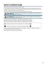
background image

MR-CV Power Regeneration Converter Unit
User's Manual

-MR-CV_

Mitsubishi Electric AC Servo System

Summary of Contents for -MR-CV

Page 1: ...MR CV Power Regeneration Converter Unit User s Manual MR CV_ Mitsubishi Electric AC Servo System ...

Page 2: ......

Page 3: ... Please follow the instructions of both levels because they are important to personnel safety Forbidden actions and required actions are indicated by the following diagrammatic symbols In this manual precautions for hazards that can lead to property damage instructions for other functions and other information are shown separately in the POINT area After reading this manual keep it accessible to t...

Page 4: ...vent an electric shock mount the converter unit before wiring To prevent an electric shock connect the protective earth PE terminal of the converter unit to the protective earth PE of the cabinet then connect the grounding lead wire to the ground To prevent an electric shock do not touch the conductive parts WARNING To prevent an electric shock do not operate the switches with wet hands WARNING To...

Page 5: ...l to another manual for reference Browsing for hardware specifications by scrolling over the components shown in product illustrations Bookmarking frequently referenced information Copying sample programs to engineering tools U S CUSTOMARY UNITS U S customary units are not shown in this manual Convert the values if necessary according to the following table Quantity SI metric unit U S customary un...

Page 6: ...HAPTER 4 STRUCTURE PARTS IDENTIFICATION 18 4 1 Parts identification 18 4 2 Opening and closing the terminal cover 24 4 3 Converter unit switch settings and operation panel 28 Switches 28 Scrolling display 29 Display sequence 30 Status display list 30 CHAPTER 5 SIGNALS AND WIRING 31 5 1 Example power circuit connections 32 Magnetic contactor control connector CN23 33 Wiring diagram 34 5 2 Explanati...

Page 7: ...cuit 69 CHAPTER 7 PROTECTION COORDINATION MODE DISABLED STANDALONE DRIVE 70 7 1 200 V class 71 7 2 400 V class 73 CHAPTER 8 CONVERTER UNIT TROUBLESHOOTING 75 8 1 Outline 75 8 2 List of alarm No warning No 75 Alarm deactivation warning deactivation 75 Explanation of the list 75 List 76 8 3 Handling methods for alarms warnings 77 61_Overcurrent 77 62_Frequency error 77 66_Process error 77 67_Open ph...

Page 8: ...verter unit 89 Connection of converter unit and servo amplifier MR J4 series 91 10 3 Molded case circuit breakers fuses magnetic contactors 93 For main circuit power supply 93 For control circuit power supply 94 10 4 AC reactor 95 10 5 Noise reduction techniques 96 10 6 Earth leakage current breaker 100 Selection method 100 Selection example 102 10 7 EMC filter recommended 103 CHAPTER 11 COMPLIANC...

Page 9: ...cribes what each block of a model name indicates Not all combinations of the symbols are available TOKYO 100 8310 JAPAN MADE IN JAPAN DATE 2016 3 MR CV55K SER A33001001 AC SERVO CAPACITY INPUT OUTPUT STD IEC EN61800 5 1 MAN IB NA 0300228 Max Surrounding Air Temp 55 C IP20 Terminal block IP00 55kW 3AC200 240V 200 0A 50Hz 60Hz DC270 324V 238 0A MSIP REI MEK TC300A911G51 Serial number Model Capacity ...

Page 10: ...ation 1 phase 170 V AC to 264 V AC Permissible frequency fluctuation Within 3 Power consumption W 30 Inrush current A Page 69 Inrush currents at power on of main circuit and control circuit Interface power supply Voltage 24 V DC 10 Current capacity A 0 35 1 Capacity kW 11 18 30 37 45 55 Protective functions Undervoltage protection regenerative error protection regenerative overvoltage shut off MC ...

Page 11: ...e 323 V AC to 528 V AC Permissible frequency fluctuation Within 3 Power consumption W 30 Inrush current A Page 69 Inrush currents at power on of main circuit and control circuit Interface power supply Voltage 24 V DC 10 Current capacity A 0 35 1 Capacity kW 11 18 30 37 45 55 75 Protective functions Undervoltage protection regenerative error protection regenerative overvoltage shut off MC drive cir...

Page 12: ...etween the MR CV_ and AC reactor or from the secondary side of the magnetic contactor to the inductive load Connect the inductive load on the power supply side beyond the area in the dotted line FR BLF 1 MCCB MCCB R S T MC MR AL _K MR Configurator2 W L1 L2 L3 V U E W V U E L CN4 CN5 CN1A CN40A CN40A CN2A CN2A CN1A L L11 L21 L L L11 L21 L L L11 L21 CN1B CN40B CN3 Molded case circuit breaker Molded ...

Page 13: ...as of the converter unit Do not subject connectors to impacts Doing so may cause a connection failure malfunction or other failures Use the product within the specified environment For details on the environment refer to the following Page 8 Standard specifications To prevent a fire or injury from occurring in the event of an earthquake or other natural disaster securely install mount and wire the...

Page 14: ... affected Mount the converter unit on a perpendicular wall in the correct vertical direction Installation For details on installation refer to the drive unit servo amplifier user s manual and instruction manual Mounting hole location diagram Converter unit Variable dimensions mm Screw size W1 W2 W3 W4 W5 A MR CV11K MR CV18K MR CV11K4 MR CV18K4 90 45 82 4 M5 MR CV30K MR CV37K MR CV45K MR CV30K4 MR ...

Page 15: ...le repair or modify the product For repair and parts replacement contact your local sales office To prevent a malfunction do not perform an insulation resistance test megger test on the converter unit Periodic inspection Perform the following inspections Check for loose terminal block screws Retighten any loose screws Check the cables and the like for scratches or cracks Inspect them periodically ...

Page 16: ...es of over 1000 m and up to 2000 m Ripple currents or other factors will deteriorate the characteristic of the smoothing capacitor The service life of the capacitor greatly varies depending on ambient temperature and operating conditions Converter unit cooling fan The cooling fan bearings will reach the end of their service life in 10000 hours to 30000 hours Therefore the cooling fan must be repla...

Page 17: ...n proportion to decreasing air density use the product within the effective load ratio and regenerative load ratio shown in the following figure Input voltage Generally withstand voltage decreases as altitude increases however there is no restriction on the withstand voltage Parts with a service life Smoothing capacitor The capacitor will reach the end of its service life in 10 years of continuous...

Page 18: ...L1 L2 L3 L L CN23 CN24 CN25 CN4 CPU L21 L11 I F MCCB MR CV_ MC drive Power supply To drive unit Converter unit protection coordination Malfunction forced stop Alarm output AC reactor Thyristor Charge lamp Cooling fan Control circuit power supply Base amplifier Voltage detection Current detection To drive unit To drive unit ...

Page 19: ...3 FUNCTION BLOCK DIAGRAM 17 3 MEMO ...

Page 20: ... Opening and closing the terminal cover 1 Display section 2 Rotary switch for converter setting SW1 12 Main circuit terminal block TE1 5 Manufacturer setting connector CN41 4 Manufacturer setting connector CN9 14 Rating plate 11 Alarm output connector CN25 7 Magnetic contactor control connector CN23 10 Control circuit terminal L11 L21 TE3 13 Protective earth PE terminal 9 L L terminal TE2 8 Charge...

Page 21: ...on coordination cable 6 I O signal connector CN24 Connect the digital I O signals Page 49 Signal device explanation 7 Magnetic contactor control connector CN23 Connect it to the coil of the magnetic contactor Page 32 Example power circuit connections Page 45 Connectors and pin assignments 8 Charge light When the main circuit is charged this light is on While the light is on do not change the conne...

Page 22: ...N41 4 Manufacturer setting connector CN9 14 Rating plate 11 Alarm output connector CN25 7 Magnetic contactor control connector CN23 10 Control circuit terminal L11 L21 TE3 13 Protective earth PE terminal 9 L L terminal TE2 8 Charge light 6 I O signal connector CN24 3 Protection coordination connector CN4 1 Display section 2 Rotary switch for converter setting SW1 ...

Page 23: ...on coordination cable 6 I O signal connector CN24 Connect the digital I O signals Page 49 Signal device explanation 7 Magnetic contactor control connector CN23 Connect it to the coil of the magnetic contactor Page 32 Example power circuit connections Page 45 Connectors and pin assignments 8 Charge light When the main circuit is charged this light is on While the light is on do not change the conne...

Page 24: ...h PE terminal 11 Control circuit terminal L11 L21 TE3 1 Display section 12 Alarm output connector CN25 8 Charge light 2 Rotary switch for converter setting SW1 6 I O signal connector CN24 15 Rating plate 7 Magnetic contactor control connector CN23 9 Manufacturer setting terminal TE2 1 4 Manufacturer setting connector CN9 3 Protection coordination connector CN4 5 Manufacturer setting connector CN41...

Page 25: ... Connect the digital I O signals Page 49 Signal device explanation 7 Magnetic contactor control connector CN23 Connect it to the coil of the magnetic contactor Page 32 Example power circuit connections Page 45 Connectors and pin assignments 8 Charge light When the main circuit is charged this light is on While the light is on do not change the connections of the wires 9 Manufacturer setting termin...

Page 26: ...minal cover 4 2 Opening and closing the terminal cover This section describes how to open and close the terminal cover Top terminal cover How to open 1 Support point A and pull up the cover 2 The cover is fixed when it is raised to the position shown in the figure A A ...

Page 27: ...PARTS IDENTIFICATION 4 2 Opening and closing the terminal cover 25 4 How to close 1 Support point A and close the cover 2 Press the cover until the installation hooks click A A Installation hooks Installation hooks ...

Page 28: ...ning and closing the terminal cover Bottom terminal cover How to open 1 Hold the left and right sides of the bottom of the terminal cover with both hands 2 Support point B and close the cover 3 The cover is fixed when it is raised to the top B B ...

Page 29: ...minal cover 27 4 How to close 1 Hold the left and right sides of the bottom of the terminal cover with both hands 2 Support point B and close the cover 3 Press the cover until the installation hooks click Installation hooks Installation hooks B B Installation hooks ...

Page 30: ...ted setting values on the rotary switch for converter setting SW1 The setting of each switch becomes effective by cycling the main circuit power supply and the control circuit power supply To enable disable forced stop protection coordination and magnetic contactor drive output set the rotary switch for converter setting The following table shows the settings of the rotary switch for converter set...

Page 31: ...play The sequence of displaying the 2 digit alarm warning number and a blank display is repeated This is an example of the alarm display for when 61 is occurring For 3 digit display The sequence of displaying the 3 digit alarm warning number and a blank display is repeated This is an example of the alarm display for when 6E 1 is occurring Initialization completed Ready off During ready on Contacto...

Page 32: ...ff and servo off Ready off charging Displayed in the servo off status Ready on charging complete Displayed in the servo on status 1 Alarms and warnings The alarm number or warning number that occurred is displayed 1 5 s 1 s 1 5 s 1 s 1 s 1 s 1 s Example When 6E 1 has occurred Example When 61 has occurred When an alarm occurs its alarm code appears Initializing Ready off charging Ready on charging ...

Page 33: ...rotective circuits such as the emergency stop If the wires are not properly secured to the terminal block the poor contact may cause the wires and terminal block to generate heat Be sure to secure the wires with the specified torque Check that no operation signal is being input to the drive unit and servo amplifier before resetting an alarm or releasing the emergency stop Failing to do so may caus...

Page 34: ...age Exogenous noise or lightning surges may degrade the characteristics of the surge absorber varistor built into the converter unit and damage it To prevent malfunction avoid bundling the converter unit s power line input cable and signal cables together or running them parallel to each other Separate the power lines from the signal cables Provide adequate protection to prevent an unexpected rest...

Page 35: ... deceleration is enabled when connecting one unit the bus voltage may drop depending on the main circuit power supply voltage and operation pattern causing a dynamic brake deceleration during forced stop deceleration If dynamic brake deceleration is not required delay the time to turn off the magnetic contactor 3 Install an overcurrent protection device molded case circuit breaker fuse etc Page 93...

Page 36: ...ic contactor with an operation delay time interval between current being applied to the coil until closure of contacts of 80 ms or less The bus voltage may drop depending on the main circuit power supply voltage and operation pattern causing a dynamic brake deceleration during a forced stop deceleration 2 Configure a sequence that shuts off the main circuit power supply when an alarm occurs on a d...

Page 37: ...hat shuts off the main circuit power supply when an alarm occurs on a drive unit 3 Install an overcurrent protection device molded case circuit breaker fuse etc to protect the branch circuit Page 93 Molded case circuit breakers fuses magnetic contactors 4 For wire size and overcurrent protection device selection refer to the following Page 89 Selection example of wires L1 L2 L3 1 3 MC1 MC2 L11 L21...

Page 38: ...the main circuit power supply voltage and operation pattern causing a dynamic brake deceleration during a forced stop deceleration 2 Configure a sequence that shuts off the main circuit power supply when an alarm occurs on a drive unit 3 Install an overcurrent protection device molded case circuit breaker fuse etc to protect the branch circuit Page 93 Molded case circuit breakers fuses magnetic co...

Page 39: ...in circuit power supply when an alarm occurs on a drive unit 3 Install an overcurrent protection device molded case circuit breaker fuse etc to protect the branch circuit Page 93 Molded case circuit breakers fuses magnetic contactors 4 For wire size and overcurrent protection device selection refer to the following Page 89 Selection example of wires L1 L2 L3 B C B C L11 L21 L L MCCB MC 1 CN25 CN4 ...

Page 40: ... circuit power supply L1 L2 L3 TE1 Supply 3 phase 200 V AC to 240 V AC 50 Hz 60 Hz power to L1 L2 and L3 Supply 3 phase 380 V AC to 480 V AC 50 Hz 60 Hz power to L1 L2 and L3 Control circuit power supply L11 L21 TE3 Supply 1 phase 200 V AC to 240 V AC 50 Hz 60 Hz power to L11 and L21 Supply 1 phase 380 V AC to 480 V AC 50 Hz 60 Hz power to L11 and L21 Drive unit L L TE2 Connect them with L and L o...

Page 41: ...d on Timing chart When combining one converter unit and one drive unit When the magnetic contactor drive output is enabled and remains ready on The main circuit power supply is not shut off even in the servo off status 1 If an electromagnetic brake is installed externally configure the circuit so that the electromagnetic brake operates with MBR as described below ON Electromagnetic brake is not ac...

Page 42: ...agnetic brake operates with MBR as described below ON Electromagnetic brake is not activated OFF Electromagnetic brake is activated 2 Give a position command after the externally installed electromagnetic brake is released 3 When in the position control mode 3 s 3 s 2 OFF ON OFF ON OFF ON OFF ON OFF ON ON OFF 0 r min 0 r min Main circuit power supply Base circuit Drive unit control circuit power s...

Page 43: ...e externally installed electromagnetic brake is released 3 When in the position control mode 4 In the drive unit parameters set the delay time Tb from when the MBR shuts off at servo off until base circuit shut off 5 This is the case when in the ready on status during servo off In the ready off status the base circuit is turned off at the same time as the servo on command is turned off Tb 0 95 ms ...

Page 44: ... min Drive unit axis the protection coordination cable is connected Servo motor speed Drive unit axis the protection coordination cable is not connected or servo amplifier Servo motor speed Main circuit power supply Drive unit axis the protection coordination cable is connected Base circuit Drive unit axis the protection coordination cable is not connected or servo amplifier Control circuit power ...

Page 45: ... 0 r min 0 r min 0 r min 0 r min Drive unit axis the protection coordination cable is connected Servo motor speed Drive unit axis the protection coordination cable is not connected or servo amplifier Servo motor speed Main circuit power supply Drive unit axis the protection coordination cable is connected Base circuit Drive unit axis the protection coordination cable is not connected or servo ampl...

Page 46: ...OFF ON ON OFF OFF ON OFF ON ON OFF 0 r min 0 r min 0 r min 0 r min Drive unit axis the protection coordination cable is connected Servo motor speed Drive unit axis the protection coordination cable is not connected or servo amplifier Servo motor speed Main circuit power supply Drive unit axis the protection coordination cable is connected Base circuit Drive unit axis the protection coordination ca...

Page 47: ...ctor set and crimping tool are required Converter unit connectors and pin assignments 1 The connector for CN23 and open tool are supplied with the converter unit CN4 CN24 CN25 A B 8 4 5 1 20 11 10 1 C 3 2 1 CN23 CN41 Leave this open CN9 Leave this open CN25 Connect to an error output signal CN4 Used to connect CN40A of the drive unit CN23 Connect to the operation coil of the magnetic contactor 1 C...

Page 48: ...isting force directly to the point of contact between the conductive part of the terminal block and the wire Applying such wire tension may lead to loose connection and power loss When opening the spring do not apply excessive force Doing so may cause damage to the housing Fabricating the wire insulator The stripped length of the wire insulator should be 5 mm to 6 mm Set the appropriate length bas...

Page 49: ...crewdriver will hold this position even when released 3 Insert the properly exposed wire into the wire insertion hole When doing so run the wire along the edge of the round hole to insert it smoothly 4 Insert the wire until it touches the back of the hole and remove the screwdriver while holding the wire 5 To confirm pull the wire lightly Do not pull harder than necessary In addition confirm that ...

Page 50: ...ing the wires When using a general purpose screwdriver use one with a blade width of 3 5 mm Do not use a screwdriver that does not fit into the operation slot or that cannot properly release the spring Model number Type Brand 210 720 Standard type made in Europe WAGO 210 120J Standard type made in Japan 210 657J Mini type made in Japan 3 5 mm ...

Page 51: ... 10 500 mA for I O interfaces The power supply capacity varies depending on the number of I O interface points to be used For sink interfaces connect the positive terminal of the 24 V DC external power supply For source interfaces connect the negative terminal of the 24 V DC external power supply Ready RDYA CN24 5 When the converter unit is ready for operation RDYA turns on This signal has the opp...

Page 52: ... to the coil of the magnetic contactor and the power supply for magnetic contactor control When the converter unit receives a start command from the drive unit a short circuit occurs between MC1 CN23 1 pin and MC2 CN23 3 pin If the magnetic contactor control connector CN23 is not used for control set the rotary switch for converter setting SW1 of the converter unit to 1 Page 28 Converter unit swit...

Page 53: ...ion 1 in the figure When the drive unit is servo off the drive unit does not detect alarms that occur on the converter unit 2 and 3 in the figure To cancel the alarm of the converter unit cycle the power of the converter unit 2 or turn on the servo on command 3 For details on which alarms can be reset by turning on the servo on command refer to the following Page 75 CONVERTER UNIT TROUBLESHOOTING ...

Page 54: ...he CPU reset command but it cannot be canceled unless the cause of the alarm is eliminated Transition No Description 1 in the figure After the drive unit has started up the main circuit power supply is turned on without alarms for the drive unit and converter unit ON OFF ON OFF ON OFF ON OFF ON OFF 3 s 1 1 ON OFF 1 5 s 3 s Drive unit Control circuit power supply Main circuit power supply Servo on ...

Page 55: ...o cancel the alarm of the converter unit cycle the power of the converter unit 2 or turn on the servo on command 3 For details on which alarms can be reset by turning on the servo on command refer to the following Page 75 CONVERTER UNIT TROUBLESHOOTING 4 in the figure If an alarm occurs in the converter unit in the servo on status an alarm also occurs on the drive unit and the status becomes servo...

Page 56: ... Transition No Description 1 in the figure If an alarm occurs on the drive unit shut off the main circuit power supply by using an external sequence 2 in the figure Turn on the main circuit power supply while the alarm on the drive unit is deactivated ON OFF ON OFF ON OFF ON OFF ON OFF 3 s 1 2 ON OFF 1 5 s 3 s Drive unit Control circuit power supply Main circuit power supply Servo on command From ...

Page 57: ...g Page 75 CONVERTER UNIT TROUBLESHOOTING 4 in the figure If an alarm occurs on the converter unit while the drive unit is servo on an alarm also occurs on the axis connected by the protection coordination cable and the status becomes servo off 5 in the figure If an alarm occurs on the converter unit input the emergency stop signal of the controller to change all axes to servo off 2 ON OFF ON OFF O...

Page 58: ...the figure After the drive unit has started up the main circuit power supply is turned on without alarms for the drive unit and converter unit 2 in the figure If an alarm occurs on any of the axes input the emergency stop signal of the controller to change all axes to servo off ON OFF ON OFF ON OFF 3 s ON OFF 1 5 s 3 s ON OFF ON OFF 2 1 1 ON OFF ON OFF ON OFF Alarm No alarm No alarm No alarm Alarm...

Page 59: ...n the servo on command refer to the following Page 75 CONVERTER UNIT TROUBLESHOOTING 4 in the figure If an alarm occurs in the converter unit in the servo on status an alarm also occurs on the drive unit and the status becomes servo off 5 in the figure If an alarm occurs on the converter unit input the emergency stop signal of the controller to change all axes to servo off 2 ON OFF ON OFF ON OFF O...

Page 60: ...the drive unit is deactivated 3 in the figure If an alarm occurs on any of the axes input the emergency stop signal of the controller to change all axes to servo off ON OFF ON OFF ON OFF ON OFF ON OFF 3 s 1 2 ON OFF 1 5 s 3 s ON OFF ON OFF 3 No alarm Alarm No alarm No alarm Alarm occurrence No alarm Drive unit axis the protection coordination cable is connected Control circuit power supply Main ci...

Page 61: ... resumes operation 1 If an electromagnetic brake is installed externally configure the circuit so that the electromagnetic brake operates with MBR as described below ON Electromagnetic brake is not activated OFF Electromagnetic brake is activated 2 Magnetic contactors with a built in external dynamic brake have a delay about 50 ms as do external relays Transition No Description 1 in the figure Whe...

Page 62: ...a built in external dynamic brake have a delay about 50 ms as do external relays 3 Wire the converter unit and drive units so that EM1 Forced stop of both are turned off at the same time Transition No Description 1 in the figure When EM1 of the converter unit is turned on the main circuit power supply is turned on 2 in the figure After the main circuit capacitor is completely charged the base circ...

Page 63: ... relay or photocoupler can be driven Install a diode D for an inductive load or install an inrush current suppressing resistor R for a lamp load Rated current 40 mA or less maximum current 50 mA or less inrush current 100 mA or less A maximum of 2 6 V voltage drop occurs in the converter unit The following connection diagram is for the sink output Refer to the following for the source output Page ...

Page 64: ... occurs in the converter unit 1 If the voltage drop a maximum of 2 6 V interferes with the relay operation apply high voltage a maximum of 26 4 V from an external source Alarm output When the converter unit is operating normally the line between B and C is closed When an alarm occurs the line between A and C becomes closed Connect the converter unit to the alarm output A B C via a relay coil or by...

Page 65: ...epending on the wiring and ground wire routing the servo amplifier may be affected by the switching noise due to di dt and dv dt of the transistor To prevent such a problem refer to the drive unit servo amplifier user s manual and instruction manual and install grounding For information on how to comply with the EMC Directive refer to EMC Installation Guidelines ...

Page 66: ...quipment within the area on the left side of the graph Graph of overload protection characteristics The table lists the converter units and corresponding graphs of overload protection characteristics Characteristic A 1 A resistive force of 100 indicates the continuous rating of the converter unit Converter unit Graph of overload protection characteristics MR CV11K MR CV30K MR CV37K MR CV45K MR CV1...

Page 67: ... indicates the continuous rating of the converter unit Characteristic C 1 A resistive force of 100 indicates the continuous rating of the converter unit 0 1 1 0 100 200 300 400 500 600 10000 1000 100 10 Load ratio 1 Operation time s 0 1 1 0 100 200 300 400 500 10000 1000 100 10 Load ratio 1 Operation time s ...

Page 68: ...ISTICS 6 1 Overload protection characteristics Characteristic D 1 A resistive force of 100 indicates the continuous rating of the converter unit 0 1 1 0 100 200 300 400 10000 1000 100 10 Load ratio 1 Operation time s ...

Page 69: ...e voltage fluctuation of the main circuit power supply terminals L1 L2 L3 of the converter unit The power supply capacity will vary according to the power impedance The actual amount of generated heat depends on the frequency of use during operation and will be within the range of At rated output and At servo off For the design of an enclosed type cabinet use the values in the tables in considerat...

Page 70: ...s generated in the cabinet Refer to the following for details about the heat generated by the converter unit Page 67 Amount of heat generated by converter unit A indicates the effective area for heat dissipation but if the cabinet is directly installed on an insulated wall that extra amount must be added to the cabinet s surface area The required heat dissipation area will vary with the conditions...

Page 71: ...g shows the inrush current reference data that will flow when 480 V AC is applied with a wiring length of 1 m Converter unit Inrush currents A0 P Main circuit power supply L1 L2 L3 Control circuit power supply L11 L21 MR CV11K 38 A attenuated to approx 10 A in 45 ms 23 A attenuated to approx 2 A in 5 ms MR CV18K 38 A attenuated to approx 10 A in 70 ms MR CV30K 81 A attenuated to approx 20 A in 65 ...

Page 72: ...han a drive unit in combination with the converter unit set the rotary switch for converter setting SW1 of the converter unit to 8 to disable protection coordination mode The regenerative capacity cannot be improved by connecting two or more converter units in a row Two or more converter units cannot be connected to the same DC power supply line When using a servo amplifier and converter unit in c...

Page 73: ...in circuit power supply 24 V DC Terminal block Servo amplifier malfunction Servo amplifier malfunction Servo amplifier malfunction Servo amplifier malfunction Converter unit malfunction Converter unit malfunction Emergency stop switch Emergency stop switch Operation ready OFF ON AC reactor Forced stop 4 SSCNET III cable SSCNET III cable Short circuit connector Packed with the servo amplifier Short...

Page 74: ...en the RSO signal is on 4 If an alarm has occurred on the converter unit configure a sequence for stopping with the emergency stop input of the controller If the controller does not have an emergency stop input use the forced stop input of the servo amplifier to stop the servo motor 5 When using the converter unit remove the wire between P3 and P4 6 Enable EM1 Forced stop 1 of the servo amplifier ...

Page 75: ...power supply 24 V DC Terminal block Servo amplifier malfunction Servo amplifier malfunction Servo amplifier malfunction Servo amplifier malfunction Converter unit malfunction Converter unit malfunction Emergency stop switch Emergency stop switch Operation ready OFF ON AC reactor Forced stop 4 SSCNET III cable SSCNET III cable Short circuit connector Packed with the servo amplifier Short circuit co...

Page 76: ...n the RSO signal is on 4 If an alarm has occurred on the converter unit configure a sequence for stopping with the emergency stop input of the controller If the controller does not have an emergency stop input use the forced stop input of the servo amplifier to stop the servo motor 5 When using the converter unit remove the wire between P3 and P4 6 Enable EM1 Forced stop 1 of the servo amplifier 7...

Page 77: ...tivated by using the methods marked with in the Alarm deactivation column of List Warnings are automatically canceled when the cause is eliminated Alarms can be deactivated by alarm reset CPU reset or power cycling Explanation of the list Alarm deactivation 1 When deactivating the alarm do so in the servo off status If the alarm is deactivated in the servo on status an alarm will occur on the driv...

Page 78: ...larm and allow a cooling time of approximately 30 minutes No Alarm Warning Alarm deactivation Alarm reset CPU reset Power cycling 61 Alarm 62 Alarm 66 Alarm 67 Alarm 68 Alarm 69 Alarm 6A Alarm 6B Alarm 6C Alarm 6E_ 1 Alarm 70 Alarm 71 Alarm 72 Alarm 73 Alarm 2 2 2 75 Alarm 76 Alarm 77 Alarm 2 2 7E Alarm 2 2 2 7F Alarm 2 2 2 E9 Warning EA Warning EB Warning EC Warning EE Warning ...

Page 79: ...ass 20 V 5 There is a problem with the surrounding environment Check the power supply for noise If there is noise take countermeasures to reduce the noise For noise reduction techniques refer to the following Page 96 Noise reduction techniques 6 The converter unit has malfunctioned Replace the converter unit then check the repeatability Cause Check action method 1 The main circuit power supply is ...

Page 80: ...eplace the converter unit then check the repeatability Cause Check action method 1 The servo motor power cable has a ground fault or has shorted Check if the servo motor power cable has a ground fault If the servo motor power cable has a ground fault correct the wiring Check if the servo motor power cable has shorted If the servo motor power cable has shorted replace the servo motor power cable 2 ...

Page 81: ...verter unit has malfunctioned Replace the converter unit then check the repeatability Cause Check action method 1 The inrush current suppression circuit of the converter unit has malfunctioned Replace the converter unit then check the repeatability Cause Check action method 1 The drive units and servo amplifiers connected to the converter unit do not meet the combination selection conditions Check...

Page 82: ... Refer to the following for connection of the power supply Page 32 Example power circuit connections 2 The bus voltage between L and L is low Check that the bus voltage between L and L is not equal to or lower than the specified value 200 V class 190 V DC 400 V class 380 V DC 3 An instantaneous power failure lasted for 60 ms or more Check that the power supply has no problems After checking cycle ...

Page 83: ...rted replace the servo motor power cable 4 The servo motor has a ground fault After disconnecting the servo motor power cables on the servo motor side check the insulation between phases U V W E If the servo motor has a ground fault or has shorted replace the servo motor 5 There is a problem with the surrounding environment Check the noise ambient temperature and other conditions and implement app...

Page 84: ...us occurred frequently If the overload status occurred frequently review the operation pattern 3 A cooling fan heat sink or opening is clogged Clean the cooling fan heat sink or openings 4 The converter unit has malfunctioned Replace the converter unit then check the repeatability Cause Check action method 1 A current larger than the continuous output current of the converter unit flowed Check the...

Page 85: ...heck if the power supply has a problem After checking cycle the power of the converter unit Cause Check action method 1 EM1 was turned off After ensuring safety turn EM1 on 2 An external 24 V DC power supply has not been inputted Input the external 24 V DC power supply 3 The converter unit has malfunctioned Replace the converter unit then check the repeatability Cause Check action method 1 The con...

Page 86: ...0 180 6 TE1 PE TE2 TE3 92 39 4 124 5 11 24 70 178 5 175 5 16 2 25 6 32 4 72 8 68 73 5 10 L21 L11 PE TE3 L L TE2 TE1 L1 L2 L3 φ6 mounting hole Approx 80 Cooling fan exhaust Intake Terminal Mounting screw Screw size M5 Tightening torque 3 24 N m TE1 Screw size M5 Tightening torque 2 0 N m TE2 Screw size M6 Tightening torque 3 0 N m TE3 Screw size M4 Tightening torque 1 2 N m PE Screw size M5 Tighten...

Page 87: ...PE TE2 TE3 92 37 5 1 5 124 5 11 24 100 178 5 175 5 26 108 88 113 5 60 150 49 52 150 2 φ6 mounting hole Approx 80 Cooling fan exhaust Intake Terminal Mounting screw Screw size M5 Tightening torque 3 24 N m TE1 Screw size M8 Tightening torque 6 0 N m TE2 Screw size M6 Tightening torque 3 0 N m TE3 Screw size M4 Tightening torque 1 2 N m PE Screw size M8 Tightening torque 6 0 N m Mass 12 1 kg ...

Page 88: ...23 5 22 22 22 256 PE 170 5 158 5 10 42 178 5 175 5 Terminal Mounting screw Screw size M5 Tightening torque 3 24 N m TE1 Screw size M10 Tightening torque 12 0 N m TE2 1 Screw size M6 Tightening torque 3 0 N m TE2 2 Screw size M6 Tightening torque 3 0 N m TE3 Screw size M4 Tightening torque 1 2 N m PE Screw size M10 Tightening torque 12 0 N m Mass 12 1 kg For eyebolts Approx 80 Cooling fan exhaust 2...

Page 89: ... 5 92 38 124 5 11 L21 L11 PE TE3 L L TE2 2 L L TE2 1 TE1 L1 L2 L3 TE1 Screw size M8 Tightening torque 6 0 N m TE2 1 Screw size M6 Tightening torque 3 0 N m TE2 2 Screw size M6 Tightening torque 3 0 N m TE3 Screw size M4 Tightening torque 1 2 N m PE Screw size M8 Tightening torque 6 0 N m Terminal Mounting screw Screw size M5 Tightening torque 3 24 N m Mass 12 1 kg Approx 80 Cooling fan exhaust 2 φ...

Page 90: ...and connector options indicated in this section for the MR CV_ power regeneration converter unit If using cables other than the cables described in this manual comply with the standards and directives applicable to each country For example NFPA 79 in North America demands the use of a listed certified product that has a thermoset insulator and is compliant with the NEC standard RHH RHW RHW 2 XHH X...

Page 91: ... that comply with each standard Selection requirements for the wire size are as follows Construction requirements Single wire set in midair Wiring length 50 m or less Selection example of wires for converter unit The following shows the wires used for wiring Use the wires given in this section or equivalent wires The following figure is a schematic diagram that shows the wires used for wiring MR C...

Page 92: ... 2 Mounting may not be possible depending on the size of the crimp terminal so use the recommended product or an equivalent Converter unit 2 Wire mm2 1 3 L1 L2 L3 L11 L21 MR CV11K 8 AWG 8 c 1 25 to 2 AWG 16 to 14 b 4 MR CV18K 22 AWG 4 i MR CV30K 38 AWG 2 h MR CV37K 60 AWG 2 0 d MR CV45K MR CV55K 80 AWG 3 0 e MR CV11K4 5 5 AWG 10 f MR CV18K4 8 AWG 8 c MR CV30K4 14 AWG 6 g MR CV37K4 22 AWG 4 a MR CV...

Page 93: ...connect one wire each from TE2 1 or TE2 2 400 V class DC power supply lead 1 Total capacity of servo amplifiers kW DC power supply lead 2 Servo amplifier capacity Wire mm2 1 9 or less 100 W 200 W 400 W 600 W 750 W 1 kW 2 AWG 14 More than 1 9 and up to 3 1 2 kW 3 5 AWG 12 More than 3 1 and up to 5 2 3 5 kW 5 kW 5 5 AWG 10 More than 5 2 and up to 8 0 7 kW 8 AWG 8 More than 8 0 and up to 11 3 11 kW 1...

Page 94: ...verall wiring length 5 m or less Junction terminals Wire as short as possible Third unit 8 mm2 assuming that the total capacity of servo amplifiers is 7 kW since 3 5 kW 2 0 kW 5 5 kW Fourth unit 3 5 mm2 assuming that the total capacity of servo amplifiers is 2 kW since 2 0 kW 2 0 kW Servo amplifier 15 kW Servo amplifier 7 kW Servo amplifier 3 5 kW Servo amplifier 2 kW First unit 60 mm2 assuming th...

Page 95: ...28 2 Use the magnetic contactor with an operation delay time interval between current being applied to the coil until closure of contacts of 80 ms or less Converter unit Molded case circuit breaker 1 Fuse Magnetic contactor 2 Frame rated current Voltage AC V Class Current A Voltage AC V MR CV11K 50 A frame 50 A 240 T 100 300 S T35 MR CV18K 100 A frame 100 A 175 S T65 MR CV30K 225 A frame 150 A 300...

Page 96: ...ker fuse etc that are connected only to the converter unit When crossing over the wiring of the control circuit power supply refer to the drive unit servo amplifier user s manual and instruction manual 1 To comply with the IEC EN UL CSA standards refer to MR CV_ Instructions and Cautions for Safe Use of AC Servos IB NA 0300228 Converter unit Molded case circuit breaker 1 Fuse Class T Fuse Class K5...

Page 97: ...6 MR CV45K MR AL 45K 160 215 175 120 70 M6 M6 9 7 MR CV55K MR AL 55K 230 220 192 120 200 M8 M10 11 5 MR CV11K4 MR AL 11K4 145 175 155 75 55 M6 M5 3 7 MR CV18K4 MR AL 18K4 145 175 155 105 55 M6 M6 5 3 MR CV30K4 MR AL 30K4 145 175 155 110 55 M6 M6 6 0 MR CV37K4 MR AL 37K4 150 215 175 110 70 M6 M6 8 5 MR CV45K4 MR AL 45K4 160 215 175 120 70 M6 M6 9 8 MR CV55K4 MR AL 55K4 230 220 210 120 200 M8 M6 10 ...

Page 98: ... parallel to each other Separate the power lines from the signal cables Use a shielded twisted pair cable for connection with the encoder and for control signal transmission and connect the external conductor of the cable to the SD terminal For grounding refer to the following Page 63 Grounding Reduction techniques for external noises that cause the converter unit drive unit to malfunction If nois...

Page 99: ...ocated near the main circuit cables and those transmitted through the power supply cables Route 1 Noises transmitted in the air Noise radiated from the power cable Route 2 Noise radiated from servo motor cable Route 3 Magnetic induction noise Routes 4 and 5 Static induction noise Route 6 Noise transmitted through electric channels Noise transmitted through power cable Route 7 Noise sneaking from g...

Page 100: ...other Insert a line noise filter to the I O cables or a radio noise filter on the input line to reduce radiated noise from the cables Use shielded wires for the signal and power lines or put the lines in separate metal conduits 4 5 6 When power cables and signal cables are laid side by side or bundled together electromagnetic and static induction noise is transmitted to the signal cables causing m...

Page 101: ...contact the manufacturer Connection diagram Dimensions Unit mm Make the connection cables as short as possible Grounding is required When using the FR BIF H with a single phase power supply insulate unconnected lead wires Power supply voltage Varistor Maximum rating Maximum limit voltage Static capacity reference value Varistor voltage rating range V1 mA Permissible circuit voltage Surge current i...

Page 102: ...of the converter unit Page 101 Example of leakage current Ig1 Ig2 per km of CV cable run in metal conduit Ig2 Leakage current on the electric channel from the output terminals of the drive unit to the servo motor Page 101 Example of leakage current Ig1 Ig2 per km of CV cable run in metal conduit Ign Leakage current when a filter is connected to the input side 4 4 mA per one FR BIF H Iga Leakage cu...

Page 103: ...le of leakage current Ig1 Ig2 per km of CV cable run in metal conduit 200 V class 400 V class 120 100 80 60 40 20 0 2 5 5 14 3 5 8 38 100 22 30 60 150 80 Leakage current mA Wire size mm 120 100 80 60 40 20 0 2 3 5 5 5 8 14 22 38 80 150 30 60 100 Leakage current mA 30 80 Wire size mm2 ...

Page 104: ...nd each term of formula 10 1 from the diagram Ign 0 not used Iga 5 mA Igm 2 5 mA Insert these values in formula 10 1 Ig 10 0 475 0 5 1 0 525 2 5 Ig 85 mA According to the result of calculation use an earth leakage current breaker with a rated sensitivity current Ig of 85 mA or more Use 200 mA for the NV SV NV SVF NV SW NV CV NV CVF NV CW NV HV series NV 22 mm2 5 m 30 mm2 5 m M Ig1 Ig2 Igm Iga Conv...

Page 105: ...the first environment residential environment only when installed by professional personnel or for use in the second environment commercial light industry and industrial environments Category C3 intended for use in the second environment commercial light industry and industrial environments Application environment EMC filter Manufacturer Model Rated current A Rated voltage VAC Operating temperatur...

Page 106: ... AC to 480 V AC power supply 1 When a surge protector is used MCCB 1 2 3 1 2 3 4 5 6 MC L1 L2 L3 L11 L21 MR CV_ L11 L21 L31 L12 L22 L32 L11 L21 Surge protector 1 EMC filter 200 V AC to 240 V AC 3 phase AC reactor Drive unit MCCB 1 2 3 1 2 3 4 5 6 MC L1 L2 L3 L11 L21 L11 L21 L31 L12 L22 L32 L11 L21 MR CV_ Surge protector 1 EMC filter 380 V AC to 480 V AC 3 phase AC reactor Drive unit ...

Page 107: ...0 355 Unit mm FSB 40 355 Unit mm 3 M4 3 M4 2 φ5 5 9 7 5 5 5 5 2 11 5 2 5 240 19 87 5 55 66 208 230 100 t 1 2 Terminal block cover Protective earth PE Mounting hole Output Input Protective earth PE Mounting plate M4 M4 90 80 21 5 290 17 1 125 11 5 259 275 2 φ5 5 7 M4 3 M5 2 φ5 5 3 M5 114 1 2 3 4 5 6 M4 t 1 2 Protective earth Input Protective earth Mounting hole Terminal cover Mounting plate Mountin...

Page 108: ...ecommended FSB 80 355 FSB 100 355 Unit mm 2 φ6 5 170 143 6 5 6 5 143 335 20 20 350 28 100 26 309 3 M8 3 M8 M6 M6 80 t 2 0 Terminal block cover Terminal block cover Mounting plate Mounting hole Mounting hole Input Output Protective earth PE Protective earth PE ...

Page 109: ...ecommended 107 10 FSB 150 355 Unit mm 385 28 210 359 183 183 100 400 26 20 20 3 M8 3 M8 M6 6 5 6 5 2 φ6 5 80 M6 t 2 0 Input Output Protective earth PE Protective earth PE Terminal block cover Terminal block cover Mounting hole Mounting hole Mounting plate ...

Page 110: ...L HF3060C SZL Unit mm 1 This applies to HF3030C SZL The mounting plate thickness of HF3060C SZL is 1 2 mm HF3100C SZL Unit mm φ4 5 66 55 78 220 210 R2 2 5 6 Approx 10 5 Approx 12 5 Approx 12 5 Mounting plate t 1 0 1 290 310 75 100 φ6 5 17 5 20 5 20 5 6 5 172 196 210 17 5 17 245 2 ...

Page 111: ...10 OPTIONS AND PERIPHERAL EQUIPMENT 10 7 EMC filter recommended 109 10 HF3150C SZL Unit mm 375 395 32 80 110 32 24 208 230 230 6 5 φ6 5 29 2 ...

Page 112: ...erating voltage 50 60 Hz DC operating start voltage Voltage protection level Nominal discharge current 8 20 μs Maximum discharge current 8 20 μs Impulse current life 8 20 μs 1000 A Manufacturer RSPD 250 U4 3 phase 250 V AC 700 V 25 1300 V 2500 A 5000 A About 300 times Okaya Electric Industries Co Ltd RSPD 500 U4 3 phase 500 V AC 1300 V 25 2000 V 2500 A 5000 A About 300 times Okaya Electric Industr...

Page 113: ...are allowed to be exported distributed or sold to China only if they are certified by this system Products that have received certification proving compliance with the relevant technical standards or products declared by the manufacturer as being compliant must carry the specified mark CCC mark Many of the technical standards to be applied are GB standards Chinese national standards which comply w...

Page 114: ...ntained in all of the homogeneous materials for this part is below the limit requirement of GB T26572 Indicates that said hazardous substance contained in at least one of the homogeneous materials for this part is above the limit requirement of GB T26572 2 Indications based on Marking for the restriction of the use of hazardous substances in electrical and electronic products SJ T11364 2014 Part n...

Page 115: ...or more lead Electrical and electronic components such as piezoelectric sensors containing lead in glass or ceramic materials but not including the dielectric ceramics used in capacitors Electrical and electronic components containing lead in a glass or ceramic matrix compound e g chip resistors Status of our products for compliance with the China RoHS directive Chinese The following table is give...

Page 116: ...tion June 2021 IB NA 0300553ENG A First edition This manual confers no industrial property rights or any rights of any other kind nor does it confer any patent licenses Mitsubishi Electric Corporation cannot be held responsible for any problems involving industrial property rights which may occur as a result of using the contents noted in this manual ...

Page 117: ...ou acknowledge we are not responsible for 2 Term of warranty after the stop of production 1 We may accept the repair at charge for another seven 7 years after the production of the product is discontinued The announcement of the stop of production for each model can be seen in our Sales and Service etc 2 Please note that the Product including its spare parts cannot be ordered after its stop of pro...

Page 118: ...trademark or registered trademark of Mitsubishi Electric Corporation in Japan and or other countries All other product names and company names are trademarks or registered trademarks of their respective companies IB NA 0300553ENG A ...

Page 119: ......

Page 120: ...notice When exported from Japan this manual does not require application to the Ministry of Economy Trade and Industry for service transaction permission HEAD OFFICE TOKYO BUILDING 2 7 3 MARUNOUCHI CHIYODA KU TOKYO 100 8310 JAPAN NAGOYA WORKS 1 14 YADA MINAMI 5 CHOME HIGASHI KU NAGOYA JAPAN ...

Reviews: