LG ARNU363DDA4, Installation Manual
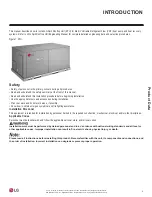
The LG ARNU363DDA4 Air Conditioner is a powerful and efficient cooling solution for your space. Ensure smooth setup and hassle-free installation with the comprehensive Installation Manual available for free download on our website. Get all the necessary instructions and guidelines to optimize the performance of your appliance. manualshive.com
Share
Download

Reviews:
No comments
Related manuals for ARNU363DDA4

FENA-01
Brand: ABB Pages: 2

FEPL-02 Ethernet POWERLINK
Brand: ABB Pages: 2

FSCA-01
Brand: ABB Pages: 52

ACH550 series
Brand: ABB Pages: 6

Relion 615 series
Brand: ABB Pages: 136

Relion 670 series
Brand: ABB Pages: 760

COM600 series
Brand: ABB Pages: 56

ACS850-04 series
Brand: ABB Pages: 296

650 series
Brand: ABB Pages: 320

EAN823
Brand: ABB Pages: 17

COM600 series
Brand: ABB Pages: 104

REC650 ANSI
Brand: ABB Pages: 370

FDNA-01
Brand: ABB Pages: 2

FPBA-01 PROFIBUS DP
Brand: ABB Pages: 2

615 Series ANSI
Brand: ABB Pages: 60

5800 Series
Brand: S&C Pages: 40

7 Series
Brand: Watts Pages: 2

6000 Series
Brand: Mako Networks Pages: 15


