background image

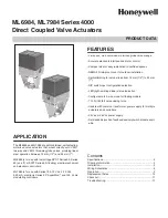
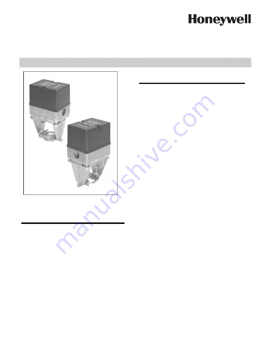
ML6984, ML7984 Series 4000
Direct Coupled Valve Actuators


PRODUCT DATA

FEATURES

• 3-wire and  Self-contained, motorized globe valve linkage

• Accurate electronic interface and motor control

• Compact size for easy installation in confined spaces

• NEMA 3R rain-proof cover for outdoor installation

• Self-calibrating for valve stroke from 13 mm (1/2

) to 25 mm

(1

)

• DIP switch input configuration selection

• LED (light-emitting diode) status indication

• Configurable to 3-wire mode for floating models

• 710 N (160 lbf) valve closing force

• Usable with common transformer power supply for multiple

actuators and controllers

• 24 Vac or 28 Vdc power supply

• Field-addable position feedback/auxiliary switch module avail-

able

APPLICATION

The ML6984 and ML7984 are self-contained, self-adjusting,
motorized  valve  actuators  that  mount  directly  onto  V5011
two-way and V5013 three-way globe valves, providing linear
stem operation between 13 mm (1/2

) and 25 mm (1

).

ML6984 is for use with low voltage SPDT Series 20, Series
60 (on-off), or SP3T Series 60 (floating) electro-mechanical
and electronic controllers.

ML7984 is for use with Series 70 0-10 Vdc, 2-10 Vdc,
4-20 mA; electronic Series 90 “SuperMod”; and 135  ohms
modulating controllers.

Contents

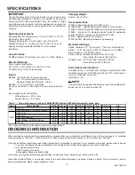
Specifications......................................................................... 2
Ordering Information............................................................... 2
Installation.............................................................................. 3
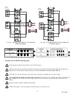
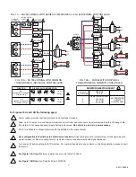
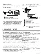
Wiring Schematics................................................................... 5
Operation................................................................................ 9
Replacement Notes................................................................. 10
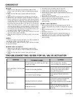
Checkout.................................................................................11
Troubleshooting ......................................................................11

Summary of Contents for 4000 Series

Page 1: ...ple actuators and controllers 24 Vac or 28 Vdc power supply Field addable position feedback auxiliary switch module avail able APPLICATION The ML6984 and ML7984 are self contained self adjusting motorized valve actuators that mount directly onto V5011 two way and V5013 three way globe valves providing linear stem operation between 13 mm 1 2 and 25 mm 1 ML6984 is for use with low voltage SPDT Serie...

Page 2: ... Stem Coupling 1 4 28 UNF thread Stroke Timing Nominal 63 seconds for 3 4 stroke Proportional to stroke length at 24 Vac Closing Force 710 N 160 lbs minimum at 24 Vac Force varies 22 N V 5 lbf volt Performance Specifications Life Expectancy at rated load and power conditions 50 000 full stroke cycles plus 1 000 000 repositions of 10 stem travel or 10 years whichever occurs first Hysteresis 5 Short...

Page 3: ...r rubber O ring over the valve stem Fig 3 Indicator will self align to the marking on the yoke after complete operating cycle FIG 2 MINIMUM MOUNTING CLEARANCE When Installing This Product 1 Read these instructions carefully Failures to follow them could damage the product or cause a hazardous condition 2 Check ratings given in instructions and on the product to ensure the product is suitable for y...

Page 4: ...astic cover from the MLx984 by loosening the two captive screws located on the top Drop the Allen Hex type of set screw included in the plastic bag into the top of the shaft hex side up 6 Tighten the set screw to lock valve stem in place Fig 6 using a 1 8 Allen wrench included FIG 4 U BOLT ASSEMBLY NOTE Use U bolt supplied with actuator Do not replace with stainless steel U bolt on chilled water v...

Page 5: ...4 WITH XL10 ELECTRONIC CONTROLLER For Figures 8A 8B and 8C the following apply 1 2 3 4 5 Power supply provides overload protection and disconnect means Allow up to 0 5 amps for each device Actuators and controller can share same transformer provided that the VA rating of the transformer is not exceeded and proper phasing is observed Do not mix a c and d c power sources Controller can be low voltag...

Page 6: ... c power sources In ML7984 T5 and W terminals are connected internally Device is compatible with 3 conductor wiring Use configuration DIP switches to select device functions Direct acting function actuator stem moves downwards with signal increases to 10V 20mA or Reverse acting function actuator stem moves upwards with signal increases to 10V 20mA Always turn power off before setting the DIP switc...

Page 7: ...n DIP switches to select device functions Direct acting function actuator stem moves upwards with signal increase or Reverse acting function actuator stem moves downwards with signal increase Turn power off before setting the DIP switches For common transformer and common controller application please consult the factory For Figure 10A Only Maximum resistance per control circuit of 280 For Figure ...

Page 8: ...function actuator stem moves upwards with signal increases to 10V 20mA or Reverse acting function actuator stem moves downwards with signal increases to 10V 20mA Turn power off before setting the DIP switches 1 2 3 4 5 8 95C 10939 4 4 5 T6 T5 B R W 3 2 ML7984 T6 T5 B R W 1 L1 L2 OR 28 Vdc 24 Vac T5 T6 3 2 ML7984 3 2 ML7984 T6 T5 B R W R W R W R W ELECTRONIC SERIES 90 W973 T775 H775 W7100 NOTE Pola...

Page 9: ... the installer may occur 5 DO NOT connect 24 Vac between any ML7984 signal input terminals DEVICE FAILURE WILL RESULT NOTE Caution GENERAL NOTE 1 The ML7984 must be field configured with the DIP switches which are located beside the terminal block See wiring diagrams for details Turn power off before setting the DIP switches 2 There is a 1 5 second delay in actuator response to every signal change...

Page 10: ...e needed Use Resistor Kit Part 272822 and set DIP switches accordingly See Figures 12 13 TO REPLACE ML684 1 The new ML6984 is a direct replacement for the old ML684A in single actuator or parallel multiple actuators hook up The old and new actuators can be mixed in the same electrical circuit For multiple actuators controlled by a common controller in parallel these actuators must be wired so that...

Page 11: ...ke sure the valve stem is locked in place with the set screw 3 Connect 24 Vac or 28 Vdc power to T5 and T6 4 Jumper R B The valve stem should move up 5 Jumper R W The valve stem should move down 6 For Floating operation open R connection Valve stem should remain in position 7 Re connect all control wiring 8 Operate the system valve actuator and controller for several cycles to ensure proper instal...

Page 12: ...ge No or low power supply 1 Check power supply 2 Check callibration cycle 3 Valve stroke length less than 1 2 or greater than 1 1 4 4 Reset device by a momentary disconnect of power at T5 and T6 Check voltage on T5 T6 terminals Change DIP switch setting ML7984 in mA mode with voltage input Signal degradation due to incompatible load impedance Output and ML Input Impedance specifications Galvanic r...

Reviews: