background image

Summary of Contents for CMU LPQ520

Page 1: ......

Page 2: ......

Page 3: ...out of print Fourth Edition November 2012 SVE 1 110 E All Rights Reserved Copyright 2003 2012 Hitachi Ltd The contents of this publication may be revised without prior notice No part of this publication may be reproduced in any form or by any means without permission in writing from the publisher Printed in Japan BI IC FL MW2007 AI10 ...

Page 4: ...rve all of those statements without fail The following are definitions of the phrases serious injury minor or moderate injury and property damage or loss not related to personal injury used in the above definitions of the safety labels Serious injury Is an injury that requires hospitalization for medical treatment has aftereffects and or requires long term follow up care Examples of serious injuri...

Page 5: ...ntenance parts in any manner not described in this manual Such a practice may result in breakdown of this equipment or peripherals injury or even death Hitachi will not be responsible for any accident or failure resulting from such mishandling Read the following safety guidelines carefully and follow them when you conduct maintenance of the machine Before starting maintenance z Maintenance of the ...

Page 6: ...ically inspected z Keep the maintenance area neat and tidy z Always put away parts materials or tools when not in use z Wear an eye protector where anything may fly about z When using sharp objects or cutting tools make sure that no part of your body lies in the path of the blade bit or point z Before finishing your work make sure that all parts removed during maintenance have been installed back ...

Page 7: ...ed If necessary use a measurement tool to ensure that the power is off z Do not touch any uninsulated conductor or surface where so instructed which remains charged for a limited time after the external power supply to the machine is disconnected z When working on a machine which has a grounding terminal make sure that the terminal is properly connected to the facility s ground z When working clos...

Page 8: ...ck z Then call an ambulance z If the victim is unconscious artificial respiration may be necessary A proper method for performing artificial respiration or resuscitation should be learned beforehand If the victim s heart is not beating cardio pulmonary resuscitation should be performed by a trained and qualified person For outbreak of fire z First shut off all the power from the machine using the ...

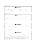
Page 9: ...is applied never touch a terminal strip or connector pin If you touch a terminal strip or connector pin while the power is applied you may receive an electric shock 2 2 CAUTION Statements chapter 3 page 3 4 CAUTION z Observe the installation procedure stated in the manual If the module is improperly installed it may drop become defective or malfunction z Do not allow wire cuttings or other foreign...

Page 10: ...ery Module chapter 6 page 6 47 CAUTION The battery cable has to be wired in a power on condition so be sure to provide protection against electric shock before you turn on the power to the CMU module chapter 6 page 6 48 CAUTION Handling batteries incorrectly will invite the danger of firing or bursting Some of used batteries may have a considerable remaining capacity Observe the general cautions f...

Page 11: ...destroyed in the event of its failure So be sure to make a backup copy of your important data stored in the memory z Read this manual thoroughly and follow all the safety precautions and instructions given in this manual before operations such as system configuration and program creation z Keep this manual handy so that you can refer to it any time you want z If you have any question concerning an...

Page 12: ...the power switch chapter 2 page 2 5 NOTICE z Be sure to mount this battery module next to the model LQP525 or LQP527 CMU module on the mount base z Never touch the connector of this battery module chapter 3 page 3 2 NOTICE The S10V Series places no limitations on the mounting location and available slots but certain limitations are imposed depending on the I O module combination For more informati...

Page 13: ...dirt or the like Ensure that the module is parallel to the mount base vertical surface as shown below when mounting If you connect a module to or disconnect it from its connector while it is tilted the connector pins may become damaged If the mount base is positioned overhead due to the employed enclosure structure use a stepladder or the like and mount the module squarely If you mount the module ...

Page 14: ...ery module and the battery cable supplied together with that battery module chapter 4 page 4 5 NOTICE Before installing the Base System shut down all Windows programs running including those resident in memory such as a virus checker If you install the Base System without shutting down these programs an error might occur while installing it If an error is encountered uninstall the Base System once...

Page 15: ... battery module s remaining life hours presented in the CMU battery information window is only a rough estimate and does not guarantee its actual remaining life or backup efficacy The battery module s useful life varies depending the ambient temperature and humidity so it is recommended that the battery module should be replaced periodically chapter 4 page 4 22 NOTICE The functions described in Su...

Page 16: ...tocol may not be displayed chapter 6 page 6 30 NOTICE Any item with CURRENT MAX HIGH and DROP each set equal to 0 is excluded from the displayed list chapter 6 page 6 47 NOTICE Be sure to replace the battery cable along with the battery module The purpose of this is to increase product reliability chapter 6 page 6 47 NOTICE This hardware unit may malfunction if it is connected poorly or has a brok...

Page 17: ...This Page Intentionally Left Blank ...

Page 18: ...n that which was delivered z The malfunction was caused by modifications or repairs made by a vendor other than the vendor that delivered the unit z The malfunction was caused by a relay or other consumable which has passed the end of its service life z The malfunction was caused by a disaster natural or otherwise for which the vendor is not responsible The warranty mentioned here means the warran...

Page 19: ...This Page Intentionally Left Blank ...

Page 20: ...on on the following hardware and program products SVE 1 110 E Hardware product CMU LQP520 LQP525 LQP527 Battery module LQZ500 Program products S 7895 03 HI FLOW SYSTEM 02 10 S 7895 29 ET NET SYSTEM 02 04 S 7895 38 BASE SYSTEM 01 15 ...

Page 21: ... System functions described under 4 2 2 Base System functions The subsection entitled 4 2 7 Battery information is added Memory areas backed up by the model LQP525 are added to the memory map described under 4 3 Memory Map Information on how to run the model LQP525 while disabling the execution of CMU programs is added to the description under 4 4 Disabling CMU Program Operations The section entit...

Page 22: ...odel numbered LQP527 is additionally made available All the safety precautions and instructions in this manual have been reviewed and necessary changes are added to them Windows 7 32 bit operating system is newly supported November 2012 In addition to the above changes all the unclear descriptions and typographical errors found are also corrected without prior notice ...

Page 23: ...This Page Intentionally Left Blank ...

Page 24: ...he standard model Example Standard model LQP520 Environmentally resistant model LQP520 Z This manual is applicable to both the standard model and environmentally resistant models Although the descriptions contained in this manual are based on the standard model follow the instructions set forth in this manual for proper use of the product even if you use the environmentally resistant model Users o...

Page 25: ... storage capacity calculations z Memory capacities and requirements file sizes and storage requirements etc must be calculated according to the formula 2n The following examples show the results of such calculations by 2n to the right of the equals signs 1 KB kilobyte 1024 bytes 1 MB megabyte 1 048 576 bytes 1 GB gigabyte 1 073 741 824 bytes z As for disk capacities they must be calculated using t...

Page 26: ...oftware 1 8 2 NAMES AND FUNCTIONS OF EACH PART 2 1 2 1 Names and Functions of Each Part 2 2 3 MOUNTING AND WIRING 3 1 3 1 Mount Base 3 2 3 2 Mounting the Module 3 2 3 2 1 Mounting the CMU module 3 2 3 2 2 Mounting the battery module 3 3 3 3 Communications Wiring 3 6 3 4 Battery Cable Wiring 3 7 4 OPERATION 4 1 4 1 CMU Operations 4 2 4 1 1 Connecting the CMU and a tool system 4 2 4 1 2 CMU mounting...

Page 27: ...onents 5 5 5 3 1 Wiring hubs and hubs to repeaters 5 5 5 3 2 Setting Single port Transceiver 5 11 5 4 System Definition Information 5 12 5 4 1 Physical address 5 12 5 4 2 IP address 5 12 5 4 3 Subnetwork mask 5 14 5 5 S Register SW510 for the LQP525 or LQP527 5 15 6 MAINTENANCE 6 1 6 1 Maintenance and Inspection 6 2 6 2 Troubleshooting 6 3 6 2 1 Procedure 6 3 6 2 2 Trouble detection and solution 6...

Page 28: ...v 6 4 Replacing the CMU Module 6 49 6 4 1 Replacing the module 6 49 6 5 Trouble Report 6 51 ...

Page 29: ...cess 5 8 Figure 5 9 Transceiver Installation 3 5 9 Figure 5 10 Laying Transceiver Cables 5 10 Figure 6 1 Troubleshooting Flow 6 3 TABLE Table 1 1 Types of System Software Tools 1 8 Table 4 1 Base System Function List 4 10 Table 4 2 Items Presented by the Performance Window 4 17 Table 4 3 Items Presented by the Error log information Window 4 19 Table 5 1 Network Component List 5 2 Table 5 2 Network...

Page 30: ...1 SPECIFICATIONS ...

Page 31: ...5 LQP527 Maximum number of modules that can mount in the mount base 1 One One Mass 240 g 200 g Battery backup capability Not provided Provided Battery backable memory Program storage memory Program storage memory and main memory 2 Battery Battery module model LQZ500 battery life one year 1 For the kinds of mount base in which the module can be mounted see 3 1 Mount Base The reader should note that...

Page 32: ...atically loaded from program memory into main memory when the module reboots The model LQP525 or LQP527 CMU module is capable of battery backing its main memory when used in conjunction with a battery module model LQZ500 1 2 3 Communications specifications Item Specifications Transmission method Serial transmission bit serial transmission Electrical interface 10BASE T Conforming to IEEE802 3 confo...

Page 33: ... and storage location of the wsvl file and should use them only for reference 1 3 2 The time when writing to the program storage memory ends Where the model LQP520 is used any write to the program storage memory ends when the user has finished all necessary interaction with the software tool they are using With the model LQP525 or LQP527 however such a write may not end even when the user has fini...

Page 34: ...S debugger system Initialize the task 5 Loading and register of task Delete task 6 RPDP S10V system svrpl 7 svdebug ld 8 NX Tools S10V system Transfer system program 9 Following DF editing OK when transmitting all settings to the destination 10 HI FLOW system Mode Online Send All processes Designated process 11 Utility PCs Delete process of PCs Exchange all processes and system 12 Utility PCs Dele...

Page 35: ...CMU module When you first use the CMU module perform the following procedure Mount the CMU and the battery module on the S10V mount base Power up the S10V controller Connect the battery cable to both the CMU and the battery module Be sure to connect this cable in a power on state Push and hold the BATT SET switch until the BATT SET LED comes on As soon as the BATT SET switch is pushed the USER LED...

Page 36: ... situation due to electromagnetic noise from such devices z The CMU module may have part or all of the contents of its memory destroyed in the event of its failure So be sure to make a backup copy of your important data stored in the memory z Read this manual thoroughly and follow all the safety precautions and instructions given in this manual before operations such as system configuration and pr...

Page 37: ...ter CPU when Windows 7 32 bit version is used Display having a resolution of 800 600 dots SVGA or higher Microsoft Windows 2000 operating system Microsoft Windows XP operating system or Microsoft Windows 7 32 bit operating system At least 64 MB of RAM when Windows 2000 is used At least 128 MB of RAM when Windows XP is used At least 1 GB of RAM when Windows 7 32 bit is used At least 10 MB of free h...

Page 38: ...2 NAMES AND FUNCTIONS OF EACH PART ...

Page 39: ...tions is detected T M switch 0 Normal mode of operation A CMU program operations disabled F Test mode Do not set this position Any other value is reserved for maintenance purposes and should not be set Station number switches 0 0 The CMU operates at the set IP address F F The CMU operates at IP address 192 192 192 1 Any other value should not be set Ethernet LINE indicator Glows to indicate that t...

Page 40: ...ndicate that a 100 Mbps link is established to the Ethernet network 10MLINK green Glows to indicate that a 10 Mbps link is established to the Ethernet network Battery replacement switch Used when you first use this CMU module or when you replace the battery module connected to it Battery backup TM setting switch 0 Selects the battery connected setting 1 Selects the battery not connected setting wh...

Page 41: ...indicate that a 100 Mbps link is established to the Ethernet network 10MLINK green Glows to indicate that a 10 Mbps link is established to the Ethernet network Battery replacement switch Used when you first use this CMU module or when you replace the battery module connected to it Battery backup TM setting switch 0 Selects the battery connected setting 1 Selects the battery not connected setting w...

Page 42: ...ector Used when connecting this battery module and a model LQP525 or LQP527 CMU module together NOTICE z Be sure to mount this battery module next to the model LQP525 or LQP527 CMU module on the mount base z Never touch the connector of this battery module LQZ500 Battery BATTERY ...

Page 43: ...This Page Intentionally Left Blank ...

Page 44: ...3 MOUNTING AND WIRING ...

Page 45: ... 2 1 Mounting the CMU module Mount the CMU module in option slots slot numbers 0 through 7 on the mount base as shown below NOTICE The S10V Series places no limitations on the mounting location and available slots but certain limitations are imposed depending on the I O module combination For more information refer to USER S MANUAL BASIC MODULE Manual number SVE 1 100 Figure 3 1 Mounting Option Mo...

Page 46: ...ower supply and investigate the problem cause z Do not perform any installation wiring handling or internal modification procedures other than stated in this manual In no event will Hitachi be responsible for personal injury or death or any damage to Hitachi s product or peripheral equipment arising out of the use of such an unauthorized procedure z While the power is applied never touch a termina...

Page 47: ...nector pins may become damaged If the mount base is positioned overhead due to the employed enclosure structure use a stepladder or the like and mount the module squarely If you mount the module obliquely the connector may become damaged CAUTION z Observe the installation procedure stated in the manual If the module is improperly installed it may drop become defective or malfunction z Do not allow...

Page 48: ...3 MOUNTING AND WIRING 3 5 NOTICE Do not disassemble or modify the module Failure to observe this precaution may result in a fire or cause the module to become defective or malfunction ...

Page 49: ...ne After connecting the connector check whether it is locked z Do not touch the connector during power on Otherwise the system may malfunction due to static electricity etc LQP520 T M RUN ALARM ERR CMU USER PROT U ST No L 10 100 BASE T ACTIVE LINE S10V Insert the cable into the connector Use a cross cable to connect two CMUs together or connect a CMU to a PC Use a straight cable to connect a CMU t...

Page 50: ...del LQP527 CMU module can be accomplished in the same way as shown below Figure 3 3 Battery Cable Wiring CAUTION The battery cable must always be wired in a power on state so be sure to provide protection against electric shock before you turn on the power to the CMU module LQP525 BATT SEL RUN ALARM ERR TX RX 100MLINK 10MLINK CMU USER PROT U ST No L 10BASE T 100BASE TX BATTERY BATT SET BATT SET Be...

Page 51: ...onnected poorly or has a broken line After connecting the connector check whether it is locked z Never use a battery module and a battery cable other than supplied as standard Always use a model LQZ500 battery module and the battery cable supplied together with that battery module ...

Page 52: ...4 OPERATION ...

Page 53: ...ibes how to connect the CMU and a tool system 4 1 1 Connecting the CMU and a tool system Connect the CMU to a tool system by way of Ethernet The CMU can be connected with a tool system in a one to one correspondence using a cross cable or in a 1 to N correspondence by way of a hub Run ladders Run HI FLOW task and NX Ladder setup tool base system HI FLOW RPDP NX and operations Tool system PC preloa...

Page 54: ...tch setting A Disable CMU program HI FLOW task and NX operations For more information see 4 4 Disabling CMU Program Operations F Let the CMU operate in test mode Do not set this position ST No U L 0 0 The CMU operates at the IP address that has previously been set by the S10V Base System of the tool system No communication can be established if the IP address is not set F F The CMU operates at IP ...

Page 55: ...ing selected the contents of the CMU s memory are lost in the event of a reset or power on reset and no alarm is issued A Disable CMU program HI FLOW task and NX operations For more information see 4 4 Disabling CMU Program Operations With this setting selected the battery backed contents of the CMU s main memory are lost in the event of a reset or power on reset so save the contents to a backup f...

Page 56: ...he Start button and choose All Programs Hitachi S10V S10V BASE SYSTEM S10V BASE SYSTEM from the Start menu on the Windows screen Click and hold the right mouse button on the S10V BASE SYSTEM and move the pointer to the desktop Then choose Copy Here from the pop up menu NOTICE Before installing the Base System shut down all Windows programs running including those resident in memory such as a virus...

Page 57: ...f the following cases 1 administrator permission is acquired by using User Account Control with a standard user account and 2 logon is made with an Administrator account that has been created using User Account Control with a standard user account If you make a logon with a user account that is different from the one you have used for the installation of the Base System the installed program may b...

Page 58: ...oose Settings Control Panel When the Control Panel opens double click on Add Remove Programs Then choose S10V BASE SYSTEM in the Change or Remove Programs tab and click the Change Remove button When the Confirm File Deletion dialog box appears click the Yes button 3 Uninstalling from Windows 7 32 bit Click on Start button on your Windows desktop and choose Control Panel When the Control Panel open...

Page 59: ...1 Double click the S10V BASE SYSTEM icon in the Windows screen Or select Start button All Programs Hitachi S10V S10V BASE SYSTEM S10V BASE SYSTEM 2 The S10V S10BASE window is displayed At startup the Connection status is set to OFFLINE so that the available functionality is limited ...

Page 60: ... there is an invalid setting of communications information the S10V S10BASE window is displayed in online state after a communication timeout is detected Depending on the setting of the communication type the communication timeout may take 2 to 3 minutes to detect Then click the button corresponding to the function of your choosing Closing the system Click or the Close button in the S10V S10BASE w...

Page 61: ...3 CLEAR USER ERR LED Clears the CMU USER LED 4 Set IP Address Sets a CMU IP address 5 Battery Information Displays the battery info currently maintained internally or sets new battery info 6 Performance Indicates the LPU processing time and CMU load percentage 7 Error Log Displays a log of errors that occurred in various modules 8 Display Status of Network Displays the RAS information of CMU ET NE...

Page 62: ...tected or when a battery not connected or a battery low condition is detected in the presence of the battery connected setting selected 4 2 5 CMU USER ERR LED clear Clears the CMU module USER LED which glows when an invalid user setting is detected 4 2 6 CMU IP address setting 1 Set CMU IP Address window The Set CMU IP Address window opens prompting you to set the IP address subnet mask broadcast ...

Page 63: ...able setup 2 Route window Sets the communication point address and gateway IP address Communication point address box Specifies the communication point network address or IP address Gateway box Specifies the gateway IP address When the box reads 0 0 0 0 it means that no IP address is entered OK button Accepts the newly entered information and closes the Route window The accepted information is wri...

Page 64: ...ing menu This button is effective only when the following two conditions are met 1 the CMU module used is of model LQP525 or LQP527 and 2 the battery connected setting is selected by setting the CMU module s BATT SEL switch in 0 position NOTICE The battery module s remaining life hours presented in the CMU battery information window is only a rough estimate and does not guarantee its actual remain...

Page 65: ... OPERATION 4 14 2 One of the following CMU buttery information windows is displayed depending on whether the battery module is connected to the CMU module or not Display when the battery is not connected ...

Page 66: ... replace the CMU module follow the procedure described under 6 4 Replacing the CMU Module The battery remainder time indicator bar graph This bar graph shows the battery module remaining life time in percent of the maximum possible life time This piece of battery information is not displayed where the battery module is not connected to the CMU module The last battery exchange date This piece of ba...

Page 67: ...emainder time and last battery exchange date and time to be recorded in the S10V Base System s operation history which is stored in the file S10log txt in the same folder in which the Base System is installed S10log txt The battery remainder time is computed as follows Battery remainder time useful battery life time accumulated power failure time where the useful battery life time is 365 days time...

Page 68: ... for execution of ladder programs and HI FLOW processes Setting value ms Set value of the sequence cycle timer CMU Load percentage Current value Current value of the CMU load percentage Maximum value Maximum value of the CMU load percentage Minimum value Minimum value of the CMU load percentage Measurement time sec Measurement time of the CMU load percentage Clear button sequence cycle Clears the ...

Page 69: ...required for execution of ladder programs and HI FLOW processes is shown shaded in the figure below 2 Change Measurement Time window Changes the CMU load percentage measurement time Measurement time box Changes the CMU load percentage measurement time setting in 1 second units The setting range is from 1 to 60 seconds The default setting is 1 second When the measurement time setting is changed fro...

Page 70: ...og error events For details on error codes and error descriptions concerning the CMU see 6 2 4 CMU error message formats For the details concerning the other modules refer to the respective module manuals The items of information presented by this Error log information window have the following meanings Table 4 3 Items Presented by the Error log information Window No Item Description 1 Module Name...

Page 71: ...ividual module basis From the list box select the module to be deleted and then click the Error Log Delete button Error Log All Delete button Deletes the entire error log information Error Log Save button Opens the Save As window which allows you to save the error log information in a file Error Log Detail button The Error Log Detail window that presents detailed information about the errors in CM...

Page 72: ...d information for the error log prior to the error log specified in the Error Log Information window Save button Opens the Save As window which allows you to save the error log information in a file 3 Save As window Save button Saves the error log information in a specified file and then closes the Save As window Cancel button Closes the Save As window without saving the error log information ...

Page 73: ... CMU ET NET opens 2 Click the Ladder and HI FLOW button to display the error log information of the errors that occurred in the Ethernet communication of the Ladder and HI FLOW Click the Socket handler button to display the error log information of the errors that occurred in the Ethernet communication of the Socket handler 3 Click the Display Status of DHP button to display the current DHP loggin...

Page 74: ...nts the trace logs of errors that occurred in the Ethernet communication of the Ladder and HI FLOW opens The content of the error log displayed is as follows Item Content ID Table number of Ladder and HI FLOW Ethernet communications management table Module Module name Trace Meaning of trace code in trace information Error code Error code for the error detected Contents Meaning of error code for th...

Page 75: ...Error Log Delete button Error Log All Delete button Deletes the entire error log information in the Ethernet communication of the Ladder and HI FLOW Save button Opens the Save As window which allows you to save the error log information in the Ethernet communication of the Ladder and HI FLOW in a file 2 Save As window Save button Saves the error log information in the Ethernet communication of the...

Page 76: ...at occurred in the Ethernet communication of the Socket handler opens The content of the error log displayed is as follows Item Content ID Socket ID of socket handler Module Module name Socket handler Name of socket handler Error code Error code from socket handler Trace Place at which the error was detected Details of error code Details of error code when the error was detected Contents Meaning o...

Page 77: ...Error Log All Delete button Deletes the entire error log information in the Ethernet communication of the Socket handler Save button Opens the Save As window which allows you to save the error log information in the Ethernet communication of the Socket handler in a file 2 Save As window Save button Saves the error log information in the Ethernet communication of the Socket handler as a specified f...

Page 78: ... modules of CMU ET NET LQE720 mounted in PCs Select the module to display or specify the status of DHP Logging mode Displays the logging mode of DHP Restart DHP logging button The logging mode of DHP will be changed to enable Stop DHP logging button The logging mode of DHP will be changed to disable Display DHP trace button The Display DHP trace window that presents the DHP trace opens ...

Page 79: ... DHP trace window are described below Item Content DHP DHP trace number displayed TIME Time the tracing was made tt tttttt where tt is seconds and tttttt microseconds EVENT Type of trace point TN Task number LV Priority level DATA1 to DATA5 Each is a piece of trace data output in hexadecimal format Refresh button Displays the Latest DHP trace Save button Opens the Save As window which allows you t...

Page 80: ...4 OPERATION 4 29 3 Save As window Save button Saves the DHP trace as a specified file and closes the Save As window Cancel button Closes the Save As window without saving the DHP trace ...

Page 81: ...indow The items displayed in the Display Status of Network window are described below Item Type of information displayed Active socket Socket information Interface Currently running network interfaces information Memory Send receive buffer management information Route Routing information IP IP protocol statistics ICMP ICMP protocol statistics TCP TCP protocol statistics UDP UDP protocol statistics...

Page 82: ...the modules of CMU ET NET LQE720 installed in PCs Select the module to display or specify the status of the network z Refresh button Displays the latest status of the network z Save button Opens the Save As window which allows you to save the network status in a file 2 Save As window Save button Saves the status of the network as a specified file and closes the Save As window Cancel button Closes ...

Page 83: ...P space CMU area CPMS space Task space GLBR space GLBW space IRSUB space Reserved System space This section of memory is battery backed in cases where a model LQP525 or LQP527 CMU module is used in conjunction with a battery module Figure 4 2 CMU Memory Map 0x00000000 0x00100000 0x00120000 0x00200000 0x00400000 0x00409000 0x00480000 0x00500000 0x00700000 0x00800000 0x01000000 0x01100000 0x03000000...

Page 84: ... run that CMU without loading in the faulty HI FLOW program or task from the flash memory After startup is achieved in this manner use various tools as needed to change the HI FLOW program or task In the case of the models LQP525 and LQP527 when the CMU is started up with the BATT SEL switch set in A position its main memory is cleared To prevent the loss of the main memory s contents back them up...

Page 85: ...This Page Intentionally Left Blank ...

Page 86: ...5 USER GUIDE ...

Page 87: ...U Table 5 1 Network Component List Description Manufacturer Model Remarks Hub Hitachi Information Technology Co Ltd With IT GS1 Switching hub Twisted pair cable Hitachi Cable Ltd HUTP CAT5 4P xxx xxx denotes the length Up to 100 m Transceiver Hitachi Cable Ltd HLT 200TB HBN200TZ HBN200TD Tap type HLT 200 Connector type Repeater Hitachi Cable Ltd HLR 200H Repeater for extending transmission distanc...

Page 88: ...ables Figure 5 1 Typical System Configuration When the distance between stations is relatively short each station can be connected directly to the hub through twisted pair cables without using any coaxial cable or transceiver as shown in Figure 5 2 Figure 5 2 Typical Hub based Configuration S S Hub S Twisted pair cable up to 100 m Terminator Transceiver cable Coaxial cable Transceiver Station Ethe...

Page 89: ...on to another Item 10BASE T Specification Number of hubs Up to 4 Up to 2 Number of segments Up to 5 Up to 3 Segment length Up to 100 m Up to 100 m Maximum network length Up to 500 m Up to 205 m 5 m or less between hubs Figure 5 3 Typical 10BASE T based Configuration Figure 5 4 Typical 100BASE TX based Configuration S Hub Hub S Hub S Hub S Segment Cable lengths not exceeding 100 m each S Hub S Segm...

Page 90: ... Enclosure Coaxial cable R250 R250 R250 Perpendicular wiring typical at the point of entry into an enclosure or elsewhere Figure 5 5 Coaxial Cable Bending Radius z Do not bend coaxial cables at or near transceiver location or near terminator location The transceiver or terminator connector would be stressed to cause defective contact Transceiver Coaxial cable 200 mm Terminator Coaxial cable 100 mm...

Page 91: ...htest looseness could result in defective contact Instructions on retightening terminator connectors are given below Retightening procedure Remove the rubber boot and connector cap Holding the coaxial connector securely by one hand clamp the terminator with the other hand and turn it firmly until it won t go any more Finally give additional tightening to the connector and check it for tightness Af...

Page 92: ... length of the male pin contact when attaching the connector Figure 5 8 No 13 Because the male pin at the terminal attachment is longer than standard it could give a crack to the female pin of the terminal connector If the male pin at the terminal attachment appears protruding when the terminal attachment is removed and the end of the coaxial cable is viewed from sideways the connector has been wo...

Page 93: ...ct with a soldering gun allow the solder inside to melt Then insert a preliminarily soldered central conductor deep into the base 13 Insert the plug shell and tighten it with a torque wrench before tightening the nut 14 Give a coat of Reich Lock to prevent loosening 15 Cover with the PVC cap to the tip of the plug shell Plug shell Covering sheath Contact Insulator Braided wire Clamp Gasket PVC cap...

Page 94: ...out phenomena similar to those described above Coaxial cable Transceiver Figure 5 9 Transceiver Installation 3 z When using a flame retardant coaxial cable use a connector type transceiver as a rule Flame retardant coaxial cables more susceptible to the effects of external torsion than regular standard coaxial cables because such force cause their internal conductor to rotate slightly z When using...

Page 95: ... z Do not overtighten twisted pair cables when securing the cables with clamps SK bands or the like do not tighten to such extent that the covering is deformed z When attaching a connector to an equipment port click it into position 7 Common tips on laying cables If the cables are laid together with a high power cable or network power cable the current flowing through the high power cable network ...

Page 96: ...ver connects Table 5 3 SQE Switch Settings Connected device CMU controller Multi port transceiver Repeater SQE switch setting ON OFF OFF For the single transceivers HLT 200 and HLT 200TB the SQE switch is contained in the case When changing the setting open the case to do the work The switch is set to ON by turning it to the SQE side of silk printing on the board SQE OFF ON ...

Page 97: ...ddress is assigned to each CMU This is a unique address the user cannot change it 5 4 2 IP address The IP address used for TCP IP and UDP IP is a 32 bit logical address An IP address consists of a network number and a host number There are three types of address assignment depending on the number of hosts i Class A The high order one bit of the network number is set to 0 Network number 8 bits Host...

Page 98: ...osts are connected to the network set the IP address of each station as follows Station A 192 001 000 001 Station B 192 001 000 002 Station C 192 001 000 003 Station D 192 001 000 004 Station E 192 001 000 005 There are two special IP addresses one indicates the entire network by setting all bits of host number of 0 and the other is the broadcast address in which all bits of host number are set to...

Page 99: ...and local host number by a subnetwork mask If a subnetwork mask is used with other than the default value the address is the broadcast address as shown in the example below Example For class B IP address Subnetwork mask Broadcast address 128 123 000 001 255 255 000 000 128 123 255 255 128 123 001 001 255 255 255 000 128 123 001 255 ...

Page 100: ...o 1 when the battery is found not connected to the CMU module Set to 0 when it is found connected to it Set to 1 when clearing of the flash memory is ended unsuccessfully Set to 1 when a write to the flash memory is ended unsuccessfully Set to 1 when a read from the flash memory is ended unsuccessfully Set to 1 when a battery low condition is detected Set to 1 when the battery life exceeds one yea...

Page 101: ...This Page Intentionally Left Blank ...

Page 102: ...6 MAINTENANCE ...

Page 103: ...function incur electrical shock hazards or develop short circuits resulting in burnouts Dust sticking condition Check to see if the module has not caught dust If dust is noticed remove it with a vacuum cleaner or other apparatus Dust could cause short circuits in its internal circuitry resulting in burnouts Module replacement Replacing the module without switching it off could cause damage to its ...

Page 104: ...d correctly Started up normally Set the switch in A position CMU program operation disabled and start up the CMU module Returned normally Load in the C mode HI FLOW program again Check the LED status information error with a tool and take a necessary action See 6 2 3 Viewing the log with a tool Returned normally Troubleshooting ended Fill in the trouble report Use 6 5 Trouble Report Contact your l...

Page 105: ...round the CMU module in the same place where high voltage equipment is grounded They must be grounded in separate places Perform grounding work conforming to Class D grounding or higher 4 Are LG and FG separated Be sure to separate the LG from the FG or vice versa because power noise enters the FG via the LG Failure to observe this rule may result in an equipment malfunction Ground the LG at the p...

Page 106: ...n click the Error Log button The Error log information window opens Module Mount Error code Contents Date and Time with the error will be displayed on the list For details on the information displayed under Contents see the description under 6 2 4 CMU error message formats Click the Error code you wish to deal with and click Error Log Detail button ...

Page 107: ...r log selected in the Error log information window will be displayed Analyze the cause of the error using the information displayed in the Error Log Detail window Refer to S10V TROUBLESHOOTING MANUAL Manual number SVE 3 001 for details displayed in the Error Log Detail window ...

Page 108: ...tem failure system error System failure built in sub error Fault severity classification F Fatal error FU Built in sub error Error message See Table 6 6 For error codes that are not enumerated in the error message list the following default error messages appear Table 6 3 Fatal Log Default Error Message List Format type Error message System failure system error System down System failure built in ...

Page 109: ...m failure kernel trap System failure built in sub stop ADT error Memory error System bus error Message frame error Buffer status report Socket error Transfer area duplication error Fault severity classification F Fatal error W Warning E Error I Information Error message See Table 6 6 and refer to SOFTWARE MANUAL OPERATION NX ACP S10V Manual number SVE 3 134 For error codes that are not enumerated ...

Page 110: ...el information Kernel Information System failure kernel trap System down System failure built in sub stop System down ADT error Program error Memory error Memory error System bus error System Bus Error Message frame error Message frame error Buffer status report Buffer status Socket error Socket error Transfer area duplication error Transfer memory address error Unit number and device number Unit ...

Page 111: ...ET RCTLNET network driver TSlib R600 communication server support library NX NXACP autonomous distributed platform MSxx Middleware xx 01 to 16 USxx Application software Fault severity classification F Fatal error E Error W Warning I Information Other fault Fault type HARD Hardware CPMS CPMS SOFT Software other than CPMS Other Code A 4 digit hexadecimal code appears to indicate a format type ...

Page 112: ...are CMU Hardware replacement 25 0500F008 Module error RERRMST Invalid Interrupt RERR interrupt status invalid Hardware CMU Hardware replacement 26 0500C001 Module error NINTR Invalid Interrupt NINT status invalid Hardware CMU Hardware replacement 27 0500B001 Module error PUINTR Invalid Interrupt PUINT status invalid Hardware CMU Hardware replacement 28 05005001 Module error RINTR Invalid Interrupt...

Page 113: ...Page Fault Instruction access page fault Software ULSUB CMU STOP Program correction 73 03030000 ULSUB down Inst Alignment Error Instruction alignment error Software ULSUB CMU STOP Program correction 74 03080000 ULSUB down Privileged Instruction Privileged instruction error Software ULSUB CMU STOP Program correction 75 03040000 ULSUB down Illegal Instruction Illegal instruction error Software ULSUB...

Page 114: ...y not connected Hardware Battery Connect the battery cable to both modules 120 07D10003 Module error Battery Low Battery low condition detected Hardware Battery Battery replacement 121 07D11001 Module error PS off Reset during writing Flash memory A power off condition or reset occurred during a write to the flash memory Load in the user program again 3 122 07D11002 Module error Flash memory Erase...

Page 115: ...sary processes to the destination at a time 7 Delete process of PCs Exchange all process and system Retry this option 8 Delete process of PCs Specify the process range Delete all the existing processes send all the necessary processes to the destination and then retry this option 9 Change system edition Delete all the existing processes send all the necessary processes to the destination and then ...

Page 116: ...race with a tool system For the tool system connection and setup procedures see 4 OPERATION Start the basic system and then click the Display Status of Network button The Display Status of Network window opens Click Display Status of DHP button ...

Page 117: ...le box Select the module for which you wish to display the status of DHP from the Module box Click Display DHP trace button after selecting the module The Display DHP trace window that presents the DHP trace selected in the Display Status of DHP window opens Analyze the behavior of the task using the DHP trace and find a way to deal with it ...

Page 118: ...sk 111 the OS switched to task 112 174 175 40 901771 40 901748 ABORT GFACT 112 112 10 10 0000006F 00000003 Task 112 was executed 176 177 178 40 901727 40 901703 40 901691 DISPATCH_E DISPATCH TASK_PRI 112 111 111 10 10 10 00000070 0000006F 0000006F 00000032 0000001C 0000001C 84DB2000 84DAF000 00000000 00000002 Delaying task 111 the OS switched to task 112 179 180 181 182 183 184 40 901611 40 901600...

Page 119: ...ror format Error code 0x030003 IOERR I O error handling uno unit number Device number Device address Detailed error code 0x030004 PRGERR Program error handling tn task number Fault address Program counter expevt register 0x030005 WDTERR WDT error handling time 0x030006 PIOERR PI O error handling slot 0x030007 MODERR Module error handling Error code Slot number HERST register INTST register 0x03000...

Page 120: ...PFREE Issuing of pfree n number of shared resources para1 para2 para3 para4 0x100012 GFACT Before After issuing of gfact fact initiation factor 0x100013 GTIME Issuing of gtime time time_t address 0x100014 EXIT Issuing of exit 0x100015 ASUSP Issuing of asusp 0x100016 ARSUM Issuing of arsum 0x10001e DHPCTL Issuing of dhpctl cmd command id trace range Trace output address 0x10001f DHPREAD Issuing of ...

Page 121: ...ormation Control information Control information 0x300010 NET_CTLR Acceptance of remote CPU control request Station number plus command Frame length plus transmission number Target type plus data length Data address Work data 0x300011 NET_START Start of NCP F I O Socket ID Task information Command code plus socket status Initiation information 1 Initiation information 2 0x300011 NET_START Transmis...

Page 122: ...he transfer source Address of the transfer destination Transfer size byte z For user Code value DHP displayed name Trace point DATA1 DATA2 DATA3 DATA4 DATA5 0x600000 USR0 User definition 0x600001 USR1 User definition 0x600002 USR2 User definition 0x600003 USR3 User definition 0x600004 USR4 User definition 0x600005 USR5 User definition 0x600006 USR6 User definition 0x600007 USR7 User definition Tab...

Page 123: ...network with a tool system For the tool system connection and setup procedures see 4 OPERATION Start the basic tool and then click the Display Status of Network button The Display Status of Network window opens Click the Display Status of Network button ...

Page 124: ...layed Active socket Socket information Interface Currently running network interfaces information Memory Send receive buffer management information Route Routing information IP IP protocol statistics ICMP ICMP protocol statistics TCP TCP protocol statistics UDP UDP protocol statistics Addition Interface cumulative information ARP ARP table information The specified type of status of network will b...

Page 125: ...ame of the protocol used over the connection Local Address The IP address of the local host source of connection If the IP address is not bound with a socket an asterisk is displayed instead Port The port number of the local host source of connection Foreign Address The IP address of the remote host destination of connection If the IP address is not bound with a socket an asterisk is displayed ins...

Page 126: ...ome available SYN_SENT Although it issued a connect SYN request to the server has not received a response ACK from it SYN_RECEIVED Has just received a connect SYN request from a client ESTABLISHED Currently performing data communication using an established TCP connection FINWAIT1 Server has sent out a FIN FINWAIT2 Has received an ACK CLOSEWAIT Has received a FIN from the server LASTACK Waiting fo...

Page 127: ...formation for the UDP protocol may not be displayed Processing reception transmission flag ACK Positive acknowledgement flag SYN Connection check flag FIN End of connection flag x no flag provided CLOSED LISTEN SYN_RECEIVED SYN_SENT ESTABLISHED FINWAIT1 CLOSING TIMEWAIT FINWAIT2 CLOSEWAIT LASTACK Waiting for a timeout to occur CLOSED Active open x SYN Close Transmission x SYN Passive open SYN SYN ...

Page 128: ...ative information where slot The slot number of the slot in which a module subjected to this display process is mounted kind Always the string EPORT is displayed as this item MTU The maximum transmission unit MTU that refers to the maximum size of data blocks into which a set of data is divided and that is transmittable by a single transfer IP address IP address used netmask Subnet mask used ...

Page 129: ... The number of message transmission failure reports that were made by hardware following a send request issued by the driver to the hardware deliver count The number of received message deliveries that were made to users input count The number of message reception reports that were made by hardware input discard error count The number of message receptions that failed due to memory shortage input ...

Page 130: ...s management information for send receive buffers memory where CURRENT The current state of mbuf MAX The status of mbuf at its maximum utilization HIGH Peak value for each item DROP The status of mbuf in the event of an overflow Cluster top address The starting address of the cluster memory ...

Page 131: ... The number of mbufs in which a socket address is stored socket options The number of mbufs in which a socket option is stored interface addresses The number of mbufs in which the address of a network interface is stored Kbytes allocated The size of the cluster memory or mbufs currently in use and the total size of the memory allocated to clusters For details on the size of the cluster memory curr...

Page 132: ...irtual network addresses an asterisk is appended to the end of the address value Gateway The IP address of the gateway associated with the destination Flags Information indicating the status of the route These flags are classified into the following three types Flag symbol Description U Indicates that the route is currently in operation G Indicates that the routing is to a gateway H Indicates that...

Page 133: ...AINTENANCE 6 32 Refcnt The number of users who are using the route Metric The number of gateways that are present in the route to the destination Interface Always the string EPORT is displayed as this item ...

Page 134: ...it is operating as a forwarding gateway default TTL The default value of TTL Time To Live that determines the maximum number of hops total packets received The total number of IP packets that were received from all existing network interfaces errors in IP headers The total number of IP packets that were discarded because of an error such as a checksum or version error in the IP header invalid IP a...

Page 135: ... shortage or some other cause packets discarded because no route The total number of IP packets that were discarded because they could not be routed due to a routing information setting error or some other cause maximum seconds fragments awaiting reassembly The maximum number of seconds during which a fragment awaiting reassembly may be placed in hold state fragment received The total number of fr...

Page 136: ... 35 fragments have been generated The total number of fragment packets that were created by the fragmentation of transmission IP packets routing entries were discarded The number of routing entries that were discarded ...

Page 137: ...ssed Destination Unreachable The total number of ICMP messages that could not be transmitted to the destination Time Exceeded The total number of ICMP messages that were discarded during routing because of a TTL Time To Live shortage Parameter Problems The total number of ICMP messages that reported on a parameter error Source Quenches The total number of ICMP messages that requested the control o...

Page 138: ...number of ICMP messages that were returned from the receiving side of ping Timestamps The total number of ICMP messages that were used as Timestamp requests Timestamp Replies The total number of ICMP messages that were used as responses to Timestamp requests Address Masks The total number of ICMP messages that were used as Address Mask Requests Address Mask Replies The total number of ICMP message...

Page 139: ...lue of retransmission timeout period expressed in milliseconds maximum value of retransmission timeout milliseconds The maximum value of retransmission timeout period expressed in milliseconds limit number of TCP connections The maximum number of connections that can be established at a time active opens The number of connections that were established to satisfy the connect requests issued to the ...

Page 140: ... total number of segments units of data each transmitted by TCP at a time that were received segments sent The total number of segments that were transmitted segments retransmit The total number of segments that were retransmitted because a reception acknowledgement was received from the destination segments received in error The number of received segments that contained an error segments send co...

Page 141: ...ts that were received no application at the destination port The number of UDP packets for which no higher level application port number could be found at the destination packets received in error The total number of UDP packets that could not be delivered to higher level services because of an error or some other cause packets sent The total number of UDP packets that were transmitted ...

Page 142: ...ed are used as internal information for maintenance purposes z Log number 001 Receiving frame success The number of frames that were received normally z Log number 002 Receiving frame fail The number of frames that caused an error during reception z Log number 003 The number of frame sending to LAN The number of frames that were sent out to the communication line z Log number 004 Total byte of the...

Page 143: ...ate collisions i e collisions detected during the transmission of the 64th or subsequent byte of data after the preamble that occurred during transmission z Log number 013 LSI Sent buffer errors The number of times the communication buffer became full z Log number 014 LSI Undershoot flow error The number of send buffer underflow errors that occurred during transmission z Log number 015 LSI Carrier...

Page 144: ...was terminated normally z Log number 024 Frame send timeout The number of frame send timeouts that occurred z Log number 129 Adapter state top 2 byte LINK 10M 100Mbps Full duplex half double state bottom 2 byte Data communication speed and full duplex half duplex state of the ET NET module used Interpret this information according to the following table Connection type Displayed value Hexadecimal ...

Page 145: ... information uno A value of 1 is always displayed as this item kind The string EPORT is always displayed as this item z Interface Information ARP entries that are registered Host The host name associated with the IP address displayed The host names displayed under this heading are those which are listed in the hosts file in the Tool currently in operation If no host names are registered in that fi...

Page 146: ...l Address The physical address of the destination registered in the ARP table If the ARP entry is invalid the string incomplete is displayed instead State The current state of the ARP entry The possible states are as follows State name displayed Meaning permanent Fixed entry published Proxy ARP entry ...

Page 147: ...ower off condition However if the LQZ500 is used in a severe environment of high temperature and high humidity replace it before its useful life reaches one year Of course when the ALARM LED is lit before the one year limit replace it Notes on battery replacement z Replace the LQZ500 module only when the following conditions are met 1 the LQP525 or LQP527 module s ALARM LED is lit and 2 the batter...

Page 148: ...the CMU module s program storage memory During the write the USER LED continues blinking this is no error indicating that the write is in progress When the BATT SET LED comes on release the BATT SET switch This procedure ends when the BATT SET LED and USER LED are both lit CAUTION The battery cable has to be wired in a power on condition so be sure to provide protection against electric shock befo...

Page 149: ... to rain and water 3 Packing method Perform packing by taking a measure to avoid mixing batteries during transportation for example by putting cushioning materials in a package Put batteries in pile up containers and put these containers in a corrugated fiberboard case or wooden case using cushioning materials in a packing unit of 10 kg or less Indicate the following contents on the packing case U...

Page 150: ...ation programs and setup information stored in the CMU module s memory z Replacement procedure Take a note of the following switch setting s provided on the existing CMU module s front panel the T M switch setting if the CMU module is of model LQP520 or the ST No and BATT SEL switch settings if it is of model LQP525 or LQP527 Take a note of the LADDER and T M switch settings provided on the LPU mo...

Page 151: ...on the initialization procedure refer to Section 3 23 Initialize the Task of the SOFTWARE MANUAL OPERATION S10V CPMS DEBUGGER For Windows Manual number SVE 3 126 Use the S10V Base System to check if the IP address of the new CMU module is identical to the one you took a note of in Step If they are not identical to each other set an identical IP address for the new module If the new CMU module is o...

Page 152: ...and time of occurrence year month day hour minute Where to make contact Address Telephone FAX E mail Model of defective module LPU model OS Ver Rev Program name Ver Rev Support program Program name Ver Rev Symptom of defect Connection load Type Model Wiring state System configuration and switch setting Space for correspondence ...

Page 153: ...This Page Intentionally Left Blank ...

Reviews: