background image

GE 

Security 


P/N 1069182 • REV 1.0 • ISS 23FEB10 

GE-DS-82 and 82-PoE Ethernet 

Managed Switch User Manual


Summary of Contents for 82-POE

Page 1: ...GE Security P N 1069182 REV 1 0 ISS 23FEB10 GE DS 82 and 82 PoE Ethernet Managed Switch User Manual ...

Page 2: ... latest product information contact your local supplier or visit us online at www gesecurity com FCC compliance This equipment has been tested and found to comply with the limits for a Class A digital device pursuant to part 15 of the FCC Rules These limits are designed to provide reasonable protection against harmful interference when the equipment is operated in a commercial environment This equ...

Page 3: ...gement 25 SNMP Based Network Management 28 The Administration Console 28 Direct Access 29 Protocols 30 Chapter 4 Web Based Management 33 About Web based Management 33 Logging on to the Switch 35 Main Web Page 36 Main Menu 37 System 38 VLAN Configuration 64 Rapid Spanning Tree 83 Trunking 94 Forwarding and Filtering 101 IGMP Snooping 105 QoS Configuration 110 Access Control List 116 MAC Limit 121 8...

Page 4: ...nfiguration 167 MAC limit 172 Port Mirroring Configuration 173 Quality of Service 174 MAC Address Configuration 177 STP RSTP Commands 179 SNMP 184 IGMP 188 802 1x Protocol 190 Access Control List 194 Binding 199 Power over Ethernet Commands GE DS 82 PoE 201 Chapter 7 Switch Operation 209 Chapter 8 Power Over Ethernet Overview 211 What is PoE 211 Chapter 9 Troubleshooting 217 Appendix A RJ 45 Pin A...

Page 5: ... Ethernet Managed Switches with 8 10 100Mbps ports and 2 Gigabit TP SFP fiber optical combo connective ability with robust layer 2 features The description of these models is below GE DS 82 8 Port 10 100Base TX 2 Port Gigabit TP SFP Combo Managed Switch GE DS 82 PoE 8 Port 10 100Base TX 2 Port Gigabit TP SFP Managed PoE Switch ...

Page 6: ...net ports with 2 Gigabit TP SFP combo ports The type 8 Fast Ethernet ports of the GE DS 82 and GE DS 82 PoE are 10 100Base TX copper RJ 45 The two Gigabit TP SFP combo ports of all models can be either 1000Base T for 10 100 1000Mbps or 1000Base SX LX through SFP Small Factor Pluggable interface The distance can be extended from 100 meters TP 550 meters Multi mode fiber up to above 10 50 70 120 kil...

Page 7: ...fers an easy to use platform independent management and configuration facility It supports standard Simple Network Management Protocol SNMP and can be monitored via any standard based management software For efficient management via WEB interface the GE DS 82 series can be programmed for basic switch management functions such as port speed configuration Port Trunking VLAN Port Mirroring Rapid Span...

Page 8: ...ged Switch WEB BASED MANAGEMENT Explains how to manage the Managed Switch by Web interface CONSOLE MANAGEMENT Describes how to use the Console Management Interface COMMAND LINE INTERFACE Explains how to manage the Managed Switch by Command Line Interface SWITCH OPERATION Explains how to operate the Managed Switch POWER OVER ETHERNET OVERVIEW Introduces the IEEE 802 3af PoE standard and PoE provisi...

Page 9: ... storm control runt CRC filtering eliminates erroneous packets to optimize the network bandwidth 8K MAC Address Table automatic source address learning and ageing Support VLAN IEEE 802 1Q Tag Based VLAN Port Based VLAN Q in Q tunneling Double Tag VLAN GVRP for dynamic VLAN Management Private VLAN Edge PVE Protect Port Supports Link Aggregation Up to 13 Trunk groups Up to 8 ports per trunk group wi...

Page 10: ... List ACL Source IP MAC Port Binding Port Security for Source MAC address entries filtering Management Switch Management Interface Telnet Command Line Interface Web switch management SNMP v1 v2c v3 switch management SSL switch management DHCP client for IP address assignment DHCP Option82 and DHCP Relay Link Layer Discovery Protocol LLDP for easy network management Built in Trivial File Transfer P...

Page 11: ...ort PoE function enable disable PoE Port Power feeding priority Per PoE port power limit PD classification detection PoE Power Supply Over Temperature Protection Product Specifications Product GE DS 82 GE DS 82 PoE Hardware Specification 10 100Mbps Copper Ports 8 10 100Base TX RJ 45 Auto MDI MDI X ports 8 10 100Base TX RJ 45 Auto MDI MDI X ports 1000Mbps Copper Ports 2 10 100 1000Base T RJ 45 port...

Page 12: ... Temperature Standard 0 50 Degree C Operating Humidity 10 to 90 Non condensing Storage Temperature 40 Degree C 85 Degree C Layer 2 Functions Management Interface Console Telnet Web Browser SNMP v1 v2c and v3 Port Configuration Port disable enable Auto negotiation 10 100Mbps full and half duplex mode selection Flow Control disable enable Bandwidth control and broadcast storm filter on each port Por...

Page 13: ... port Ingress Egress bandwidth control in steps of128Kbps Port Mirror RX TX Both 1 to 1 monitor Security 802 1x Port Based Network access control MAC Limit Static MAC MAC Filtering Access Control List Supports up to 220 rule entries SNMP MIBs RFC 1157 SNMP MIB RFC 1213 MIB II RFC 1215 Trap RFC 2863 Interface MIB RFC 1493 Bridge MIB RFC 2674 Extended Bridge MIB Q Bridge RFC 1643 RFC 2665 EtherLike ...

Page 14: ...tree protocol IEEE 802 1w Rapid spanning tree protocol IEEE 802 1p Class of service IEEE 802 1Q VLAN Tagging IEEE 802 1x Port Authentication Network Control IEEE 802 3af Power over Ethernet GE DS 82 PoE only RFC 768 UDP RFC 793 TFTP RFC 791 IP RFC 792 ICMP RFC 2068 HTTP RFC 1112 IGMP version 1 RFC 2236 IGMP version 2 Cable Fiber optic cable 50 125µm or 62 5 125µm multi mode fiber cable 100Base FX ...

Page 15: ...nt panel illustrations in this chapter display the unit LED indicators Before connecting any network device to the Managed Switch please read this chapter completely Hardware Description Switch Front Panel The unit front panel provides a simple interface for monitoring the Managed Switch Figure 1 shows the front panels of the Managed Switches Figure 1 GE DS 82 and GE DS 82 PoE Switch front panels ...

Page 16: ...ng the power off The following table summarizes the Reset button functions Reset Button Pressed and Released Function About 1 3 seconds Reboots the Managed Switch Until the PWR LED goes out Resets the Managed Switch to Factory Default configuration The Managed Switch will then reboot and load the default settings as below Default Password admin Default IP address 192 168 0 100 Subnet mask 255 255 ...

Page 17: ... 10 100 1000Base T port SFP interfaces LED Color Function LNK ACT 1000 Green Lit indicates the port is operating at 1000Mbps Off indicates the port is operating at 10Mbps or 100Mbps Blink indicates the Switch is actively sending or receiving data over that port LNK ACT 100 Green Lit indicates the port is operating at 100Mbps Off indicates the port is operating at 10Mbps or 1000Mbps Blink indicates...

Page 18: ...s or 100Mbps Blink indicates the Switch is actively sending or receiving data over that port LNK ACT 100 Green Lit indicates the port is operating at 100Mbps Off indicates the port is operating at 10Mbps or 1000Mbps Blink indicates the Switch is actively sending or receiving data over that port NOTE 1 Press the RESET button once The Switch will reboot automatically 2 Press the RESET button for abo...

Page 19: ...connect to the console port on the device After the connection users can run any terminal emulation program Hyper Terminal ProComm Plus Telix Winterm and so on to enter the startup screen of the device POWER NOTICE 1 The Managed Switch is a power required device it will not work unless it is receiving power If your networks must be active at all times we recommend that the Switch be connected to a...

Page 20: ...helf Installation NOTE Refer to the environmental restrictions listed in the Product Specification when selecting a location for the Managed Switch Step 1 Attach the rubber feet to the recessed areas on the bottom of the Managed Switch Step 2 Place the Managed Switch on a desktop or shelf near an AC power source as shown in Figure 5 Step 3 Ensure there is enough ventilation space between the Manag...

Page 21: ...ect the power cable plug to a standard wall outlet C Switch the power switch on the rear panel to ON When the Managed Switch receives power the Power LED should light and remain solid Green Rack mount Installation Use the following instructions to install the Managed Switch in a 19 inch standard rack Step 1 Place the Managed Switch on a hard flat surface with the front panel positioned towards the...

Page 22: ...the rack as shown in Figure 7 Figure 7 Mounting the GE DS 82 in a rack Step 6 Follow steps 4 and 5 of the Desktop Installation section to connect the network cabling and supply power to the Managed Switch SFP Transceiver Installation This section describes how to insert an SFP transceiver into an SFP slot SFP transceivers are hot pluggable and hot swappable You can insert and remove a transceiver ...

Page 23: ... The following list of approved GE Security SFP transceivers is correct at the time of publication 1000Base SX LX SFP transceiver SFP1000SX 220 SFP 1000BASE SX SFP transceiver Multi mode 220m SFP1000LX 10Km SFP 1000BASE LX SFP transceiver Single Mode 10km NOTE We recommend that only approved GE Security SFP transceivers be used on the Managed Switch If you insert an SFP transceiver that is not sup...

Page 24: ...fiber cable 1 Attach the duplex LC connector on the network cable into the SFP transceiver 2 Connect the other end of the cable to a device switches with SFP installed fiber NIC on a workstation or a Media Converter 3 Check the LNK ACT LED of the SFP slot on the front of the Switch Ensure that the SFP transceiver is operating correctly 4 Check the Link mode of the SFP port if the link failed Co wo...

Page 25: ...h User Manual 21 Figure 9 Pulling out the SFP transceiver CAUTION Never pull out the module without pull the handle or the push bolts on the module Pulling out the module with too much force could damage the module and SFP module slot of the Managed Industrial Switch ...

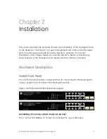
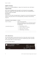
Page 26: ...Chapter 2 Installation 22 GE DS 82 and 82 PoE Ethernet Managed Switch User Manual ...

Page 27: ...omputer and the system It also contains information about port connection options This chapter covers the following topics Requirements Management Access Overview Administration Console Access Web Management Access SNMP Access Standards Protocols and Related Reading Requirements Clients of subscribers running Windows 98 ME NT4 0 2000 XP MAC OS9 or later Linux UNIX or other platform compatible with...

Page 28: ...e Managed Switch Management Access Overview The Managed Switch gives you the flexibility to access and manage it using any or all of the following methods Web browser interface An external SNMP based network management application The Administration Console The Administration Console and Web browser interface support are embedded in the Managed Switch software and are available for immediate use E...

Page 29: ... based Telnet functionality and HyperTerminal built into Windows 95 98 NT 2000 ME XP operating systems Secure Must be near switch or use dial up connection Not convenient for remote users Modem connection may prove to be unreliable or slow Web Browser Management The Managed Switch offers management features that allow users to manage the Managed Switch from anywhere on the network through a standa...

Page 30: ...ere x is a number between 1 and 254 except 100 and the default subnet mask is 255 255 255 0 Figure 10 PC connected to Switch over Ethernet cable 192 168 0 x PC Workstation with IE Browser RJ 45 UTP Cable Managed Switch IP Address 192 168 0 100 IP Address Login to the managed Switch 1 Using Internet Explorer 6 0 enter the IP address http 192 168 0 100 the factory default IP address or the IP addres...

Page 31: ...agement GE DS 82 and 82 PoE Ethernet Managed Switch User Manual 27 Figure 11 Login screen 3 After entering the username and password the main screen appears as shown in Figure 12 Figure 12 Web main screen of Managed Switch ...

Page 32: ...ows the get community string it can only read Mobs The default gets and sets community strings for the Managed Switch are public Figure 13 SNMP Management 192 168 0 x PC Workstation with SNMP application Managed Switch IP Address 192 168 0 100 IP Address Internet Intranet The Administration Console The Administration Console is an internal character oriented and command line user interface for per...

Page 33: ... to the administration console is achieved by directly connecting a terminal or a PC equipped with a terminal emulation program such as HyperTerminal to the Managed Switch console serial port When using this management method a straight DB9 RS 232 cable is required to connect the switch to the PC After making this connection configure the terminal emulation program to use the following parameters ...

Page 34: ...a software program such as Telnet that allows you to establish a management session from a Macintosh a PC or a UNIX workstation Because Telnet runs over TCP IP you must have at least one IP address configured on the Managed Switch before you can establish access to it with a virtual terminal protocol Terminal emulation differs from a virtual terminal protocol in that you must connect a terminal di...

Page 35: ...s 192 168 0 100 and the default telnet port number is 23 then press the OK button Figure 17 The Connect to dialog window Log on to the Console Make sure the device finished booting Once the telnet has connected to the device the hyper terminal will display the login request Then the following message asks the login user name and password The factory default password as following and the login scre...

Page 36: ...d data collection programs SNMP runs on top of the User Datagram Protocol UDP offering a connectionless mode service Management Architecture All of the management application modules use the same Messaging Application Programming Interface MAPI By unifying management methods with a single MAPI configuration parameters set using one method console port for example are immediately displayable by the...

Page 37: ...n Java Applets with an aim to reduce network bandwidth consumption enhance access speed and present an easy viewing screen NOTE By default IEv6 0 or later does not allow Java Applets to open sockets The user has to explicitly modify the browser setting to enable Java Applets to use network ports The Managed Switch can be configured through an Ethernet connection make sure the manager PC is set on ...

Page 38: ...192 168 1 1 with subnet mask 255 255 255 0 via console then the manager PC should be set at 192 168 1 x where x is a number between 2 and 254 to do the relative configuration on manager PC Requirements Workstations of subscribers running Windows 98 ME NT4 0 2000 2003 XP MAC OS9 or later Linux UNIX or other platform compatible with TCP IP protocols Workstation installed with Ethernet NIC Network Ca...

Page 39: ...s field to access the Web interface The factory default IP Address is http 192 168 0 100 Figure 19 Login screen 2 The login screen will appear Enter the default username and password or the username password you have changed via console to login to the main screen of Managed Switch User name admin Password admin 3 After entering the username and password the main screen appears as shown in Figure ...

Page 40: ...h PoE features so where there are differences they will be indicated Main Web Page The Main web page allows you to configure the Managed Switch This section describes how to use the Managed Switch s Web browser interface to configure and manage it Panel Display Near the top of the web page the web agent displays an image of the Managed Switch s ports The Mode can be set to display different inform...

Page 41: ...h User Manual 37 Figure 21 Port Control page The port states are illustrated as follows State Disabled Down Link RJ 45 Ports SFP Ports PoE Ports Main Menu The Main menu is located on the left side of the Main Web Page This is where all the configuration menus can be accessed ...

Page 42: ...ides basic system description including contact information IP CONFIGURATION Sets the IP address for management access SNMP CONFIGURATION Configure SNMP agent and SNMP Trap FIRMWARE UPGRADE Upgrade the firmware via TFTP server or Web Brower file transfer CONFIGURATION BACKUP Save View the Managed Switch configuration to remote host Upload the switch configuration from remote host FACTORY DEFAULT R...

Page 43: ...e 23 Basic System Information screenshot This page includes the following fields OBJECT DESCRIPTION MODEL NAME Displays the system name of the Managed Switch DESCRIPTION Describes the Managed Switch MAC ADDRESS Displays the unique hardware address assigned by manufacturer default FIRMWARE VERSION Displays the Managed Switch s firmware version HARDWARE VERSION Displays the current hardware version ...

Page 44: ...ins in the switch s address table The value is a multiple of 6 Default is 300 seconds Broadcast Storm Filter Mode To configure broadcast storm control enable it and set the upper threshold for individual ports The threshold is the percentage of the port s total bandwidth used by broadcast traffic When broadcast traffic for a port rises above the threshold you set broadcast storm control becomes ac...

Page 45: ... button to complete the configuration IP Configuration The Managed Switch is a network device which needs to be assigned an IP address to be identified on the network Users have to decide a means of assigning IP address to the Managed Switch What is an IP address Each device such as a computer which participates in an IP network needs a unique address on the network It s similar to having a US mai...

Page 46: ... DESCRIPTION DHCP Enable or disable the DHCP client function When DHCP function is enabled the Managed Switch will be assigned an IP address from the network DHCP server The default IP address will be replaced by the assigned IP address on DHCP server After the user clicks Apply a popup dialog shows up to inform the user that when the DHCP client is enabled the current IP will lose and user should...

Page 47: ...user has to assign the gateway in this column field The default gateway is 192 168 0 254 SNMP Configuration SNMP Overview The Simple Network Management Protocol SNMP is an application layer protocol that facilitates the exchange of management information between network devices It is part of the Transmission Control Protocol Internet Protocol TCP IP protocol suite SNMP enables network administrato...

Page 48: ...specific MIB modules Network management protocol A management protocol is used to convey management information between agents and NMSs SNMP is the Internet community s de facto standard management protocol SNMP Overview SNMP itself is a simple request response protocol NMSs can send multiple requests without receiving a response Get Allows the NMS to retrieve an object instance from the agent Set...

Page 49: ...be an alpha character And the first or last character must not be a minus sign The allowed string length is 0 to 255 System Location The physical location of this node e g telephone closet 3rd floor The allowed string length is 0 to 255 and the allowed content is the ASCII characters from 32 to 126 System Contact The textual identification of the contact person for this managed node together with ...

Page 50: ...information RW Read write Enables requests accompanied by this community string to display MIB object information and to set MIB objects ADD button Press the button to add the management SNMP community strings on the Managed Switch REMOVE button Press the button to remove the management SNMP community strings that you defined before on the Managed Switch Trap Managers A trap manager is a managemen...

Page 51: ... entry index keys are Security Model and Security Name The SNMPv3 Groups Configuration screen in Figure 30 appears Figure 30 SNMP Configuration Interface This page includes the following fields Object Description Group Name A string identifying the group name that this entry should belong to The allowed string length is 1 to 15 V1 V2c USM Indicates the security model that this entry should belong ...

Page 52: ...eys are View Name and OID Subtree The SNMPv3 Views Configuration screen in Figure 31 appears Figure 31 SNMP configuration interface This page includes the following fields Object Description View Name A string identifying the view name that this entry should belong to The allowed string length is 1 to 15 Included Excluded Indicates the view type that this entry should belong to Possible view type ...

Page 53: ...ess control at The object instance level SNMPv3 Access Configure the SNMPv3 access table on this page The entry index keys are Group Name Security Model and Security Level The SNMPv3 Accesses Configuration screen in Figure 32 appears Figure 32 SNMP configuration interface This page includes the following fields Object Description Group Name A string identifying the group name that this entry shoul...

Page 54: ...ects for which this request may request the current values The allowed string length is 1 to 16 Write View The name of the MIB views defining the MIB objects for which this request may potentially SET new values The allowed string length is 1 to 16 Notify View Set up the notify view Remove Check to delete the selected entry It will be deleted during the next save SNMPv3 usm user Configure SNMPv3 u...

Page 55: ...or MD5 authentication protocol the allowed string length is 8 to 32 Private Key 8 32 A string identifying the privacy pass phrase The allowed string length is 8 to 32 Remove Check to delete the selected entry It will be deleted during the next save Firmware Upgrade It provides the functions allowing the user to update the switch firmware via the Trivial File Transfer Protocol TFTP server Before up...

Page 56: ...are Upgrade page contains fields for downloading system image files from the Local File browser to the device The Web Firmware Upgrade screen in Figure 35 appears Figure 35 HTTP Firmware Upgrade interface To open the Firmware Upgrade screen do the following 1 Click System then Web Firmware Upgrade 2 The Firmware Upgrade screen is displayed as in Figure 35 3 Click the Browse button of the main page...

Page 57: ...guration Backup TFTP Restore Configuration You can restore a previous backup configuration from the TFTP server to recover the settings Before doing that you must locate the image file on the TFTP Server first and the Managed Switch will download the flash image Figure 36 Configuration Restore interface This page includes the following fields OBJECT DESCRIPTION TFTP Server IP Address Type in your ...

Page 58: ...lash ROM to the TFTP server for the purpose of recovering the configuration later It helps you to avoid wasting time on configuring the settings by backing up the configuration Figure 37 Configuration Backup interface This page includes the following fields OBJECT DESCRIPTION TFTP Server IP Address Type in your TFTP server IP Backup File Name Type in the file name ...

Page 59: ...witch User Manual 55 Factory Default Reset switch to default configuration Click reset to reset all configurations to the default value Figure 38 Factory Default interface System Reboot Reboot the switch Click reboot to reboot the system Figure 39 System Reboot interface ...

Page 60: ...web interface This page includes the following settings OBJECT DESCRIPTION Syslog Server IP IP address of syslog server Log level None never send syslog message to syslog serverme and Max Age parameters of the root bridge regardless of how it is configured Major only send major syslog to syslog server eg link up down system warm cold start All send all syslog message to syslog server Port Configur...

Page 61: ...as Force you have to set the speed and duplex mode manually Speed It is available for selecting when the Negotiation column is set as Force When the Negotiation column is set as Auto this column is read only Duplex It is available for selecting when the Negotiation column is set as Force When the Negotiation column is set as Auto this column is read only Flow Control Whether or not the receiving n...

Page 62: ...alid range is 0 8000 The unit is 128K 0 disable rate control 1 8000 valid rate value Security A port in security mode will be locked without permission of address learning Only the incoming packets with SMAC already existing in the address table can be forwarded normally User can disable the port from learning any new MAC addresses then use the static MAC addresses screen to define a list of MAC a...

Page 63: ...the status of each port clear at a glance like Port Link Up Link Down status negotiation Link Speed Rate Control Duplex mode and Flow Control Figure 42 Port Status interface Port Statistics The following chart shows the current statistic information that displays the real time packet transfer status for each port The user might use the information to plan and implement the network or check and fin...

Page 64: ... Tx Bad Packet The counts of transmitting bad packets including undersize less than 64 octets oversize CRC Align errors fragments and jabbers packets via this port Rx Good Packet The counts of receiving good packets via this port Rx Bad Packet The counts of receiving good packets including undersize less than 64 octets oversize CRC error fragments and jabbers via this port Tx Abort Packet The abor...

Page 65: ...raffic in switched networks Traffic through a port can be monitored by one specific port That is traffic goes in or out a monitored port will be duplicated into the sniffer port Figure 44 Port Mirror application Configuring the port mirroring by assigning a source port from which to copy all packets and a destination port where those packets will be sent ...

Page 66: ... Analysis port to LAN analyzer or netxray Monitored Port The port you want to monitor The monitor port traffic will be copied to the Analysis port You can select one monitor per ports in the switch User can choose which port that they want to monitor in only one sniffer type NOTE When the Mirror Mode set to RX or TX and the Analysis Port is selected the packets to and from the Analysis Port will n...

Page 67: ...orts Figure 46 Protected Port setting web interface This page includes the following fields OBJECT DESCRIPTION Port ID Identify the Managed Switch interface Protected Enable the Protected function on the selected port If the check box is not shown as then this port a unprotected port and it can communicate with any ports including protected ports Group 1 Set the protected port to be Group 1 member...

Page 68: ...e forwarded to only members of the VLAN on which the broadcast was initiated NOTE 1 No matter what basis is used to uniquely identify end nodes and assign these nodes VLAN membership packets cannot cross VLAN without a network device performing a routing function between the VLAN 2 The Managed Switch supports IEEE 802 1Q VLAN The port untagging function can be used to remove the 802 1 tag from pac...

Page 69: ...ny port can be configured as either tagging or untagging The untagging feature of IEEE 802 1Q VLAN allows VLAN to work with legacy switches that don t recognize VLAN tags in packet headers The tagging feature allows VLAN to span multiple 802 1Q compliant switches through a single physical connection and allows Spanning Tree to be enabled on all ports and work normally Some relevant terms Tagging T...

Page 70: ... another with the VLAN information intact This allows 802 1Q VLAN to span network devices and indeed the entire network if all network devices are 802 1Q compliant Every physical port on a switch has a PVID 802 1Q ports are also assigned a PVID for use within the switch If no VLAN are defined on the switch all ports are then assigned to a default VLAN with a PVID equal to 1 Untagged packets are as...

Page 71: ...moved from the default VLAN and Link Aggregation Groups In order to use VLAN segmentation in conjunction with port link aggregation groups you can first set the port link aggregation group s and then you may configure VLAN settings If you wish to change the port link aggregation grouping with VLAN already in place you will not need to reconfigure the VLAN settings after changing the port link aggr...

Page 72: ...2 1 tag from packet headers to maintain compatibility with devices that are tag unaware Port Based VLAN Packets can go among only members of the same VLAN group Note all unselected ports are treated as belonging to another single VLAN If the port based VLAN enabled the VLAN tagging is ignored In order for an end station to send packets to different VLANs it itself has to be either capable of taggi...

Page 73: ...new VLAN group Figure 49 appears 4 Type a name and Group ID for the new VLAN the available range is 2 4094 5 From the Available ports box select ports to add to the Managed Switch and click Add 6 Click Apply 7 You will see the VLAN Group displays 8 If the port based VLAN groups list over one page please click Next Page to view other VLAN groups on other page 9 Use Delete button to delete unwanted ...

Page 74: ...field to specify a name for the VLAN It can be up to 16 alphanumeric characters long including blanks Group ID You can configure the ID number of the VLAN by this item This field is used to add VLANs one at a time The VLAN group ID and available range is 2 4094 Port Indicate port 1 to port 26 Add Defines the interface as a Port Based member of a VLAN Member Remove Forbidden ports are not included ...

Page 75: ... or untagged Tagged Ports with tagging enabled will put the VID number priority and other VLAN information into the header of all packets that flow into those ports If a packet has previously been tagged the port will not alter the packet thus keeping the VLAN information intact The VLAN information in the tag can then be used by other 802 1Q compliant devices on the network to make packet forward...

Page 76: ...Group Configuration interface 1 Click the hyperlink VLAN Static VLAN to enter the VLAN configuration interface 2 Select 802 1Q at the VLAN Operation Mode to enable the 802 1Q VLAN function 3 Click Add to create a new VLAN group or Edit to management exist VLAN groups Then the VLAN Group column appears 4 Input a VLAN group ID and available range is 2 4094 ...

Page 77: ... port Figure 52 appears 6 After setup completed please press Apply button to take effect 7 Please press Back for return to VLAN configuration screen to add other VLAN group 8 If there are many groups that over the limit of one page you can click Next to view other VLAN groups 9 Use Delete button to delete unwanted VLAN 10 Use Edit button to modify existing VLAN group ...

Page 78: ...anks VLAN ID You can configure the ID number of the VLAN by this item This field is used to add VLANs one at a time The VLAN group ID and available range is 2 4094 Port Indicate port 1 to port 26 Untag Packets forwarded by the interface are untagged UnTag Member Tag Defines the interface as a tagged member of a VLAN All packets forwarded by the interface are tagged The packets contain VLAN informa...

Page 79: ... section provides 802 1Q Ingress Filter of each port from the Switch the screen in Figure 53 appears Figure 53 802 1Q Ingress filter interface This page includes the following fields OBJECT DESCRIPTION NO Indicate port 1 to port 26 PVID Set the port VLAN ID that will be assigned to untagged traffic on a given port This feature is useful for accommodating devices that you want to participate in the...

Page 80: ...tiple customers across their networks QinQ tunneling is used to maintain customer specific VLAN and Layer 2 protocol configurations even when different customers use the same internal VLAN IDs This is accomplished by inserting Service Provider VLAN SPVLAN tags into the customer s frames when they enter the service provider s network and then stripping the tags when the frames leave the network A s...

Page 81: ...When leaving the MAN the tag is stripped and the original VLAN tag with the customer related VID is again available This provides a tunneling mechanism to connect remote costumer VLANs through a common MAN space without interfering with the VLAN tags All tags use EtherType 0x8100 or 0x88A8 where 0x8100 is used for customer tags and 0x88A8 are used for service provider tags In cases where a given s...

Page 82: ...eserve customer VLAN IDs for traffic crossing the service provider network Q in Q Tunnel Setting Business customers of service providers often have specific requirements for VLAN IDs and the number of VLANs to be supported The VLAN ranges required by different customers in the same service provider network might overlap and traffic of customers through the infrastructure might be mixed Assigning a...

Page 83: ... 55 Q in Q Tunnel Setting interface To configure the QinQ Port do the following 1 Enable global QinQ function select QinQ enable Enable 2 Fill QinQ Tpid 3 Enable port QinQ function select QinQ checkbox for special port 4 Enable port QinQ Uplink function select QinQ Uplink checkbox for special port ...

Page 84: ...tual local area networks VLANs within a larger network GVRP conforms to the IEEE 802 1Q specification which defines a method of tagging frames with VLAN configuration data This allows network devices to dynamically exchange VLAN configuration information with other devices GVRP Setting To configure GVRP Enable global GVRP function select GVRP enable Enable Enable port GVRP function select GVRP che...

Page 85: ... Ethernet Managed Switch User Manual 81 Figure 56 GVRP Configuration web interface This page includes the following fields OBJECT DESCRIPTION GVRP Enable global GVRP function Port Indicate port 1 to port 10 Port GVRP Enable selected port GVRP function ...

Page 86: ... VLANs from being learned via GVRP Figure 57 GVRPTable web interface This page includes the following fields OBJECT DESCRIPTION VLAN ID Display the learned VLANs via GVRP protocol on GVRP enabled ports The Managed Switch allows displaying up to 128 dynamic VLAN entries Port Members Identify the GVRP enabled port that dynamic VLAN is learned from ...

Page 87: ...between switches that form loops within the network When multiple links between switches are detected a primary link is established Duplicated links are blocked from use and become standby links The protocol allows for the duplicate links to be used in the event of a failure of the primary link Once the Spanning Tree Protocol is configured and enabled primary links are established and duplicated l...

Page 88: ...e topology All switches connected to the LAN on which the packet is transmitted will receive the BPDU BPDUs are not directly forwarded by the switch but the receiving switch uses the information in the frame to calculate a BPDU and if the topology changes initiates a BPDU transmission The communication between switches via BPDUs results in the following One switch is elected as the root switch The...

Page 89: ...gy The forward delay timer is used to allow the network topology to stabilize after a topology change In addition STP specifies a series of states a port must transition through to further ensure that a stable network topology is created after a topology change Each port on a switch using STP exists is in one of the following five states Blocking the port is blocked from forwarding or receiving pa...

Page 90: ...ome major network problems if the STP assistance is not applied If switch A broadcasts a packet to switch B switch B will broadcast it to switch C and switch C will broadcast it to back to switch A and so on The broadcast packet will be passed indefinitely in a loop potentially causing a network failure In this example STP breaks the loop by blocking the connection between switch B and C The decis...

Page 91: ...he Priority setting or influencing STP to choose a particular port to block using the Port Priority and Port Cost settings is however relatively straight forward Figure 59 Before Applying the STA Rules In this example only the default STP values are used Figure 60 After Applying the STA Rules ...

Page 92: ...for both levels NOTE On the switch level STP calculates the Bridge Identifier for each switch and then sets the Root Bridge and the Designated Bridges On the port level STP sets the Root Port and the Designated Ports The following are the user configurable STP parameters for the switch level PARAMETER DESCRIPTION DEFAULT VALUE Bridge Identifier Not user configurable except by setting priority belo...

Page 93: ...0 000 100Mbps Fast Ethernet ports 20 000 1000Mbps Gigabit Ethernet ports 0 Auto Default Spanning Tree Configuration Feature Default Value Enable state STP disabled for all ports Port priority 128 Port cost 0 Bridge Priority 32 768 NOTE The Hello Time cannot be longer than the Max Age Otherwise a configuration error will occur Observe the following formulas when setting the above parameters Max Age...

Page 94: ...the highest priority and is selected as the root If the value is changed the user must reboot the switch The value must be a multiple of 4096 according to the protocol standard rule Max Age 6 40 The number of seconds a switch waits without receiving Spanning tree Protocol configuration messages before attempting a reconfiguration Enter a value between 6 through 40 Hello Time 1 10 The time that con...

Page 95: ... Each switch in a spanning tree adopts the Hello Time Forward Delay time and Max Age parameters of the root bridge regardless of how it is configured Root Bridge Information This page provides a status overview for all RSTP bridge instances The displayed table contains a row for each RSTP bridge instance where the column displays the following information The RSTP Bridge Status screen in Figure 62...

Page 96: ...s the sum of the Port Path Costs on the least cost path to the Root Bridge Root Port The switch port currently assigned the root port role Maximum Age Path Cost to the Designated Root for the Root Bridge Hello Time Minimum time between transmissions of Configuration BPDUs Forward Delay Derived value of the Root Port Bridge Forward Delay parameter Port Configuration This web page provides the port ...

Page 97: ... function allows the P2P status of the link to be manipulated administratively YES means the port is regarded as a point to point link NO means the port is regarded as a shared link AUTO means the link type is determined by the auto negotiation between the two peers Admin Edge The port directly connected to end stations won t create bridging loop in the network To configure the port as an edge por...

Page 98: ... or network cables to expand the connection speed beyond the limits of any one single port or network cable The Managed Switch supports two types of port trunk technology Static Trunk LACP The Link Aggregation Control Protocol LACP provides a standardized means for exchanging information between Partner Systems on a link to allow their Link Aggregation Control instances to reach agreement on the i...

Page 99: ... Switch User Manual 95 Aggregator Setting This section provides Port Trunk Aggregator Setting of each port from the Managed Switch the screen in Figure 64 appears Figure 64 Port Trunk Aggregator setting interface two ports are added to the left field with LACP enabled ...

Page 100: ...mber ports but member ports won t know that they should be aggregated together to form a logic trunk group Work ports This column field allows the user to type in the total number of active port up to four With LACP static trunk group e g you assign four ports to be the members of a trunk group whose work ports column field is set as two the exceed ports are standby redundant ports and can be aggr...

Page 101: ...Chapter 4 Web Based Management GE DS 82 and 82 PoE Ethernet Managed Switch User Manual 97 Figure 65 Assigning 2 ports to a trunk group with LACP disabled Figure 66 Static Trunking Group information ...

Page 102: ...u will see the trunking group information between two switches on the tab of Aggregator Information Switch 1 configuration 1 Set System Priority of the trunk group The default is 1 2 Select a trunk group ID by pull down the drop down menu bar 3 Enable LACP 4 Include the member ports by clicking the Add button after selecting the port number and the column field of Work Ports changes automatically ...

Page 103: ...p ID by pull down the drop down menu bar 8 Enable LACP 9 Include the member ports by clicking the Add button after selecting the port number and the column field of Work Ports changes automatically Figure 68 Switch 2 configuration interface 10 Click on the tab of Aggregator Information to check the trunked group information as the illustration shown above after the two switches are configured ...

Page 104: ...ty Having set up the LACP aggregator on the tab of Aggregator Setting you can configure the state activity for the members of the LACP trunk group You can tick or cancel the checkbox beside the state label When you remove the tick mark of the port and click Apply the port state activity will change to Passive Figure 70 State Activity of Switch 1 ...

Page 105: ...ocol packet from the opposite device Forwarding and Filtering The frames of Ethernet Packets contain a MAC address SMAC address which shows the MAC address of the equipment sending the frame The SMAC address is used by the switch to automatically update the MAC table with these dynamic MAC addresses Dynamic entries are removed from the MAC table if no frames with the corresponding SMAC address hav...

Page 106: ...ic entry Click Clear to clear the dynamic MAC addresses information of the current port shown on the screen Static MAC Table You can add a static MAC address that remains in the switch s address table regardless of whether the device is physically connected to the switch This saves the switch from having to re learn a device s MAC address when the disconnected or powered off device is active on th...

Page 107: ...MAC Address Enter the MAC address of the port that should permanently forward traffic regardless of the device network activity Port Num Pull down the selection menu to select the port number VLAN ID The VLAN ID for the entry MAC Filtering By filtering MAC address the switch can easily filter the pre configured MAC address and become more secure You can add and delete filtering MAC address ...

Page 108: ... DS 82 and 82 PoE Ethernet Managed Switch User Manual Figure 73 MAC Filtering interface This page includes the following fields OBJECT DESCRIPTION MAC Address Enter the MAC address that you want to filter VLAN ID The VLAN ID for the entry ...

Page 109: ...eed to inform nearby routers that they will become members of a multicast group The Internet Group Management Protocol IGMP is used to communicate this information IGMP is also used to periodically check the multicast group for members that are no longer active In the case where there is more than one multicast router on a sub network one router is elected as the queried This router then keeps tra...

Page 110: ...Chapter 4 Web Based Management 106 GE DS 82 and 82 PoE Ethernet Managed Switch User Manual Figure 75 Multicast flooding Figure 76 IGMP Snooping multicast stream control ...

Page 111: ...Group Membership Query if Group Address is Present 0x16 Membership Report version 2 0x17 Leave a Group version 2 0x12 Membership Report version 1 IGMP packets enable multicast routers to keep track of the membership of multicast groups on their respective sub networks The following outlines what is communicated between a multicast router and a multicast group member using IGMP A host sends an IGMP...

Page 112: ... Join Group Send Report Start Timer Query Received Start Timer Report Received Stop Timer Timer Expried Send report Idle Member Non Member Delaying Member IGMP Querier A router or multicast enabled switch can periodically ask their hosts if they want to receive multicast traffic If there is more than one router switch on the LAN performing IP multicasting one of these devices is elected querier an...

Page 113: ...BJECT DESCRIPTION IGMP Protocol Enable or disable the IGMP protocol IGMP Fastleave Enable or disable Fast Leave on the port IGMP Querier Enable or disable the IGMP query function The IGMP query information will be displayed in IGMP status section NOTE Fast Leave The Managed Switch can be configured to immediately delete a member port of a multicast service if a leave packet is received at that por...

Page 114: ...es Assigning priorities to traffic for example to set higher priorities to time critical or business critical applications Applying security policy through traffic filtering Provide predictable throughput for multimedia applications such as video conferencing or voice over IP by minimizing delay and jitter Improve performance for specific types of traffic and preserve performance as the amount of ...

Page 115: ... Source Address VLAN TAG Ethernet Type Data FCS 6 bytes 6 bytes 4 bytes 2 bytes 46 1517 bytes 4 bytes Set up the COS priority level With the drop down selection item of Priority Type above being selected as COS only COS first this control item will then be available to set the queuing policy for each port Priority Queue Service settings QoS settings allow customization of packet priority in order ...

Page 116: ...iority queue These options represent the number of higher priority packets sent before one lower priority packet is sent For example 8 Highest 4 SecHigh 2 SecLow 1 Lowest means that the switch sends 8 highest priority packets before sending 4 second high priority packet before sending 2 second low priority packet before sending 1 lowest priority packet 802 1p priority 0 7 Set up the COS priority l...

Page 117: ...t 1 to port 26 Port Priority Each port has 8 priority levels 0 7 or Disable to be chosen 7 is the highest priority TOS DSCP TOS DSCP priority is obtained through a 6 bit Type of Service TOS or Differentiated Service Code Point DSCP to 3 bit priority mapping The Type of Service TOS octet in the IPv4 header is divided into three parts Precedence 3 bits TOS 4 bits and MBZ 1 bit The Precedence bits in...

Page 118: ...6 bit 2 bit VER 0100 Header Size DiffServ RES Preamble Destination Address Source Address VLAN TAG Optional Ethernet Type 0800 Data FCS 6 bytes 6 bytes 4 bytes 2 bytes 2 bytes 46 1517 bytes 4 bytes The DSCP is six bits wide allowing coding for up to 64 different forwarding behaviors The DSCP retains backward compatibility with the three precedence bits so that non DSCP compliant TOS enabled device...

Page 119: ...The values of the IP DSCP header field within the incoming packet 0 63 Priority Specify which 802 1p priority to map the corresponding IP DSCP The value is 0 7 TOS DSCP Port Configuration Set up IP TOS DSCP mapping to 802 1p priority when receiving IPv4 IPv6 packets the Managed Switch allows to by port configuring the QoS Status This TOS DSCP Port Configuration page is to configure the IP TOS DSCP...

Page 120: ...priate access rights to a given object depending on certain aspects of the process that is making the request principally the process s user identifier Access Control List ACL is a mechanism that implements access control for a system resource by listing the identities of the system entities that are permitted or denied to access the resource The screen in following figure appears Packets can be f...

Page 121: ...the following fields IPv4 ACL OBJECT DESCRIPTION DEFAULT VALUE Group ID 1 247 max 247 ACL group Action Permit Deny Permit Permit packet cross switch Deny Drop packet Permit VLAN Any VID Any Any VLAN id VID 1 4094 A certain VLAN id Any Packet Type IPv4 Non IPv4 Binding IPv4 Set Ipv4 packet field Non IPv4 Set non Ipv4 packet field Binding Set binding entry IPv4 ...

Page 122: ...is range from 0 to 255 Any IP Fragment Set this field if Packet Type is IPv4 else ignore Uncheck Check Uncheck Not check IP fragment field Check Check IP fragment field Uncheck L4 Protocol Set this field if Packet Type is IPv4 else ignore Any ICMP 1 IGMP 2 TCP 6 UDP 17 Any Protocol Set this field if Packet Type is IPv4 else ignore 0 255 If protocol not find in L4 Protocol field you can direct assi...

Page 123: ... OBJECT DESCRIPTION DEFAULT VALUE Group ID 1 247 max 247 ACL group Action Permit Deny Permit Permit packet cross switch Deny Drop packet Permit VLAN Any VID Any Any VLAN ID VID 1 4094 A certain VLAN ID Any Packet Type IPv4 Non IPv4 Binding IPv4 Set Ipv4 packet field Non IPv4 Set non Ipv4 packet field Binding Set binding entry IPv4 Ether Type Set this field if Packet Type is Non IPv4 else ignore An...

Page 124: ...ld select Binding OBJECT DESCRIPTION DEFAULT VALUE Group ID 1 247 max 247 ACL group Action Permit Deny Permit Permit packet cross switch Deny Drop packet Permit VLAN Any VID Any Any Vlan id VID 1 4094 A certain vlan id Any Packet Type IPv4 Non IPv4 Binding IPv4 Set Ipv4 packet field Non IPv4 Set non Ipv4 packet field Binding Set binding entry IPv4 MAC Address is represent a digit from 0 9 and A F ...

Page 125: ...AC address table should be blocked MAC Limit Configuration The Layer 2 MAC Limit function can be per port configured for security management purposes When the port is in MAC Limit mode the port will be locked without permission of address learning Only the incoming packets with Source MAC already existing in the address table can be forwarded normally User can disable the port from learning any ne...

Page 126: ...AC Limit Port Status This table displays current MAC Limit status of each port Figure 85 MAC Limit MAC Limit Port Status This page includes the following fields OBJECT DESCRIPTION Port Number Indicates port 1 to port 26 Limit Display the current MAC Limit configuration and status of each port ...

Page 127: ...orized clients from connecting to a LAN through publicly accessible ports The authentication server authenticates each client connected to a switch port before making available any services offered by the switch or the LAN Until the client is authenticated 802 1X access control allows only Extensible Authentication Protocol over LAN EAPOL traffic through the port to which the client is connected A...

Page 128: ...on 3 0 RADIUS operates in a client server model in which secure authentication information is exchanged between the RADIUS server and one or more RADIUS clients Switch 802 1X device controls the physical access to the network based on the authentication status of the client The switch acts as an intermediary proxy between the client and the authentication server requesting identity information fro...

Page 129: ... the client can initiate authentication by sending an EAPOL start frame which prompts the switch to request the client s identity NOTE If 802 1X is not enabled or supported on the network access device any EAPOL frames from the client are dropped If the client does not receive an EAP request identity frame after three attempts to start authentication the client transmits frames as if the port is i...

Page 130: ...s identity In this situation the client does not respond to the request the port remains in the unauthorized state and the client is not granted access to the network In contrast when an 802 1X enabled client connects to a port that is not running the 802 1X protocol the client initiates the authentication process by sending the EAPOL start frame When no response is received the client sends the r...

Page 131: ...ransitions from up to down or if an EAPOL logoff frame is received the port returns to the unauthorized state System Configuration 802 1x makes use of the physical access characteristics of IEEE802 LAN infrastructures in order to provide a means of authenticating and authorizing devices attached to a LAN port that has point to point connection characteristics and of preventing access to that port ...

Page 132: ...et the UDP destination port for authentication requests to the specified RADIUS Server Accounting Port Set the UDP destination port for accounting requests to the specified RADIUS Server Shared Key Set an encryption key for using during authentication sessions with the specified RADIUS server This key must match the encryption key used on the RADIUS Server NAS Identifier Set the identifier for the...

Page 133: ...zed The specified port is required to be held in the unauthorized state FA Force Authorized The specified port is required to be held in the authorized state Authorize The specified port is set to the Authorized or Unauthorized state in accordance with the outcome of an authentication exchange between the Supplicant and the authentication server No The specified port works without complying with 8...

Page 134: ...riod the port waits for retransmit next EAPOL PDU during an authentication session Default value is 30 seconds Supplicant Timeout Set the period of time the switch waits for a supplicant response to an EAP request Default value is 30 seconds Server Timeout Set the period of time the switch waits for a server response to an authentication request Default value is 30 seconds Max Requests Set the num...

Page 135: ...t Hotel Campus Factory Warehouse can install the Access Point any where with no hesitation 10 12 watts IP Surveillance Enterprise Museum Campus Hospital Bank can install IP Camera without limits of install location no need electrician to install AC sockets 3 12 watts PoE Splitter PoE Splitter split the PoE 48V DC over the Ethernet cable into 5 9 12V DC power output It frees the device deployment f...

Page 136: ...s cannot be connected When this value is exceeded ports will be deactivated according to user defined priorities The power budget is managed according to the following user definable parameters maximum available power ports priority the maximum allowable power per port The Over Temperature Protection of the PoE Switch offers a safety and stable PoE operating by limit the output power according to ...

Page 137: ...160 Watts Power limit mode Allow you to configure the power limit mode of Web Smart Device You can choose Port Priority Deliver PoE power by port priority setting Total Limit Set limit value of the total POE port provided power to the PDs Power Allocation Show the total watts usage of PoE Switch PoE Function Can enable or disable the PoE function Priority Set port priority for the POE power manage...

Page 138: ...PD classification is to provide information about the maximum power required by the PD during operation Class 0 is the default for PDs However to improve power management at the PSE the PD may opt to provide a signature for Class 1 to 3 The PD is classified based on power The classification of the PD is the maximum power that the PD will draw across all input voltages and operational modes A PD sh...

Page 139: ...erent subnet RFC 1542 So DHCP server can provide IP addresses to clients spanning multiple subnets instead of deploying a DHCP server on every subnet Configuring DHCP Relay Option82 To configure DHCP Option82 1 Enable the global option82 function select DHCP Option82 enable 2 Enable port option82 function select Option82 checkbox for special port 3 Select DHCP Router Port 4 Click Apply To configur...

Page 140: ...d port Relay IP Type the IP addresses of the DHCP Relay IP LLDP Link Layer Discovery Protocol LLDP is used to discover basic information about neighboring devices on the local broadcast domain LLDP is a Layer 2 protocol that uses periodic broadcasts to advertise information about the sending device Advertised information is represented in Type Length Value TLV format according to the IEEE 802 1ab ...

Page 141: ...lo time You can change LLDP hello time value The time interval between the transmission LLDP info packets Value range is from 5 to 32768 Default value is 30 LLDP hold time You can change LLDP hold time value The hold time the hello time is the TTL time in the LLDP info packets Value range is from 2 to 10 Default value is 4 PerPort Configuration This page allows the user to inspect and configure th...

Page 142: ...ckets Value range is from 5 to 32768 Default value is 30 LLDP hold time You can change LLDP hold time value The hold time the hello time is the TTL time in the LLDP info packets Value range is from 2 to 10 Default value is 4 Port Status You can change LLDP port status to Tx_only Rx_only Tx_and_Rx Disable Tx_only LLDP transmit the packet of the port only Rx_only LLDP receive the packet of the port ...

Page 143: ...t the console port directly through PC without the need of Null Modem Please refer to the Administration Console section on page 28 to get more information about how to connect to the console interface of GE DS 82 PoE with HyperTerminal on Microsoft Windows platform Once the terminal has connected to the device power on the GE DS 82 PoE the terminal will display that it is running testing procedur...

Page 144: ...anual Figure 96 GE DS 82 PoEConsole Login screen NOTE For security reasons please change and memorize the new username and password after this first setup Username Max 6 Min 1 characters Password Max 6 Min 1 characters Only enter commands in lowercase letters in the console interface ...

Page 145: ...IP Address 192 168 0 100 Subnet Mask 255 255 255 0 To check the current IP address or modify a new IP address for the Switch please use the procedures as follow Show the current IP address 1 On Switch prompt enter configure 2 On Switch config prompt enter show ip 3 The screen displays the current IP address Subnet Mask and Gateway As show in Figure 97 Figure 97 Show IP information screen ...

Page 146: ... 0 Switch config ip default gateway 192 168 1 254 The previous command would apply the follow settings for the Switch IP 192 168 1 100 Subnet Mask 255 255 255 0 Gateway 192 168 1 254 Figure 98 Set IP address screen 2 Repeat Step 1 to check if the IP address has changed If the IP is successfully configured the Managed Switch will apply the new IP address setting immediately You can access the Web i...

Page 147: ... attachment under UNIX can use an emulator such as TIP Commands Level The following table lists the CLI commands and description Modes Access Method Prompt Exit Method About This Model User EXEC Begin a session with your switch switch Enter logout or quit The user commands available at the user level are a subset of those available at the privileged level Use this mode to Perform basic tests Displ...

Page 148: ...Chapter 5 Console Management 144 GE DS 82 and 82 PoE Ethernet Managed Switch User Manual ...

Page 149: ...rnet Managed Switch User Manual 145 Chapter 6 Command Line Interface Operation Notice To enter the configuration mode you need to be in the privileged mode and then types in the command configure Switch configure Switch config ...

Page 150: ...cursor forward one word Backspace Delete the character before the cursor Del Delete the character at the cursor The following generic function keys provide functions in all of the menus Command Help You may enter at any command mode and the CLI will return all possible commands at that point along with some description of the command System Commands Command Description show running config Display ...

Page 151: ...rt list specifies the ports to be turn on or off If not entered all ports are turn on or off port nego Description Set port negotiation Syntax port nego force auto nway force port list Parameters port list specifies the ports to be set If not entered all ports are set port speed Description Set port speed in mbps and duplex Syntax port speed 10 100 1000 full half port list Parameters port list spe...

Page 152: ...isables flow control in half duplex mode port list specifies the ports to be set If not entered all ports are set port rate Description Set port effective ingress or egress rate Syntax port rate ingress egress 0 8000 port list Parameters 0 8000 specifies the ingress or egress rate 0 8000 port list specifies the ports to be set If not entered all ports are set port priority Description Set port pri...

Page 153: ...ters port list specifies the ports to be set If not entered all ports are set show port status Description Show port status including port State Link Trunking VLAN Negotiation Speed Duplex Flow control Rate control Priority Security BSF control Switch config show port status Port 1 Information State on Link down Trunking none VLAN DEFAULT Priority disable Security off Port 2 Information State on L...

Page 154: ...n Show port statistics including TxGoodPkt TxBadPkt RxGoodPkt RxBadPkt TxAbort Collision and DropPkt Parameters port id specifies the port to be shown Switch config show port statistics Port 1 Information TxGoodPkt 0 TxBadPkt 0 RxGoodPkt 0 RxBadPkt 0 TxAbort 0 Collision 0 DropPkt 0 Port 2 Information TxGoodPkt 0 TxBadPkt 0 RxGoodPkt 0 RxBadPkt 0 TxAbort 0 Collision 0 ...

Page 155: ...3 Information More show port protection Description Show protected port information Switch config show port protection Port Protected Group 1 off 1 2 off 1 3 off 1 4 off 1 5 off 1 6 off 1 7 off 1 8 off 1 9 off 1 10 off 1 11 off 1 12 off 1 13 off 1 14 off 1 15 off 1 16 off 1 17 off 1 18 off 1 19 off 1 20 off 1 ...

Page 156: ...vers to the switch Trunk can also provide a redundant link for fault tolerance If one link in the trunk failed the switch can balance the traffic among the remaining links NOTE The 10 100 Mbps port cannot be trunked with gigabit port port 25 26 All ports in the same trunk group will be treated as a single port If a trunk group exists the ports belonging to that trunk will be replaced by TRUNK in t...

Page 157: ... be added lacp Description Specifies the added trunk group to be LACP enabled Syntax lacp no lacp specifies the added trunk group to be LACP disabled Parameters port list specifies the ports to be set active port list specifies the ports to be set to LACP active no trunk Description Delete an existing trunk group Syntax no trunk trunk id Parameters trunk id specifies the trunk group to be deleted ...

Page 158: ...rity no lacp system priority Description Set LACP system priority to the default value 32768 show lacp status Description Show LACP enable disable status and system priority show lacp Description Show LACP information Switch config show lacp status LACP is enabled LACP system priority 32768 show lacp agg Description Show LACP aggregator information Syntax show lacp agg trunk id Parameters trunk id...

Page 159: ...AN group VLAN prevents users from accessing network resources of another on the same LAN thus the users can not see the hard disks and printers of another user in the same building VLAN can also increase the network performance by reducing the broadcast traffic and enhance the security of the network by isolating groups The GE DS 82 PoEsupports two types of VLANs Port based IEEE 802 1Q tag based O...

Page 160: ...can belong to more than one VLAN The difference between a port based VLAN and a tag based VLAN is that the tag based VLAN truly divided the network into several logically connected LANs Packets rambling around the switches can be forwarded more intelligently In the figure shown below by identifying the tag broadcast packets coming from computer A in VLAN1 at sw1 can be forwarded directly to VLAN1 ...

Page 161: ...s received on a port you can govern the switch to drop it or not if it is an untagged packet Furthermore if the received packet is tagged but not belonging to the same VALN group of the receiving port you can also control the switch to forward or drop the packet The example below configures the switch to drop the packets not belonging to the same VLAN group and forward the packets not containing V...

Page 162: ...ort based VLAN mode NAME specifies the VLAN group name cpu port no cpu port specifies the CPU port belong this VLAN group LIST specifies the ports to be set to VLAN members LIST specifies the ports to be set to tagged members If not entered all members set to untagged e g switch config vlan add 1 vlan1 cpu port 1 4 This VLAN entry has four members from port1 to port4 and all members are untagged n...

Page 163: ...ine Interface GE DS 82 and 82 PoE Ethernet Managed Switch User Manual 159 show vlan Description Show VLAN entry information Syntax show vlan 1 4094 Parameters 1 4094 specifies the VLAN id null means all valid entries e g ...

Page 164: ...1 Untagged Port2 Untagged Port3 Untagged Port4 Untagged Port5 Untagged Port6 Untagged Port7 Untagged Port8 Untagged Port9 Untagged Port10 Untagged Port11 Untagged Port12 Untagged Port13 Untagged Port14 Untagged Port15 Untagged Port16 Untagged More Port17 Untagged Port18 Untagged Port19 Untagged Port20 Untagged Port21 Untagged Port22 Untagged Port25 Untagged Port26 Untagged Trk1 Untagged ...

Page 165: ...ed Switch User Manual 161 show vlan static Description Show static VLAN entry information show vlan pvid Description Show port default VLAN id Syntax show vlan pvid LIST Parameters LIST specifies the ports to be showed If not entered all port s PVID will be showed e g ...

Page 166: ...Switch User Manual Switch config show vlan pvid Port PVID Port1 1 Port2 1 Port3 1 Port4 1 Port5 1 Port6 1 Port7 1 Port8 1 Port9 1 Port10 1 Port11 1 Port12 1 Port13 1 Port14 1 Port15 1 Port16 1 Port17 1 Port18 1 Port19 1 Port20 1 Port21 1 More Port22 1 Port25 1 Port26 1 Trk1 1 ...

Page 167: ... specifies the non members packet will be forwarded or not If set enable forward only packets with VID matching this port s configured VID enable disable specifies the untagged frame will be dropped or not If set enable drop untagged frame show vlan filter Description Show VLAN filter setting Syntax show vlan filter LIST Parameters LIST specifies the ports to be showed If not entered all ports fil...

Page 168: ...rop Forward Port5 Drop Forward Port6 Drop Forward Port7 Drop Forward Port8 Drop Forward Port9 Drop Forward Port10 Drop Forward Port11 Drop Forward Port12 Drop Forward Port13 Drop Forward Port14 Drop Forward Port15 Drop Forward Port16 Drop Forward Port17 Drop Forward Port18 Drop Forward Port19 Drop Forward Port20 Drop Forward More Port21 Drop Forward Port22 Drop Forward Port25 Drop Forward Port26 D...

Page 169: ...sable MAC address age out mac age time 6 1572858 Parameters 6 1572858 specifies the MAC address age out time Must be divisible by 6 Type the number of seconds that an inactive MAC address remains in the switch s address table show mac age time Description Show MAC address age out time broadcast Description Set broadcast storm filter mode to off 1 2 1 4 1 8 1 16 Syntax broadcast mode off 1 2 1 4 1 ...

Page 170: ...er IP multicast IP multicast packets filter Broadcast Packets Broadcast Packets filter Syntax broadcast select unicast multicast control packet ip multicast broadcast Collision Retry Description Collision Retry setting Syntax Collision Retry off 16 32 48 Parameters 16 32 48 In Half Duplex collision retry maximum is 16 32 48 times and packet will be dropped if collisions still happen Disable In Hal...

Page 171: ...stname name str Parameters name str specifies the switch name If you would like to have spaces within the name use quotes around the name no hostname Reset the switch name to factory default setting no password Description Set or remove username and password for manager or operator Syntax no password manager operator all Parameters The manager username and password is also used by the web UI ...

Page 172: ...teway Description Set the default gateway IP address Syntax ip default gateway ip addr show ip Description Show IP address subnet mask and the default gateway show info Description Show basic information including system info MAC address and versions Switch config show info Model name GE DS 242 PoE Description 24 Port 10 100Mbps 2G TP SFP Combo Managed Switch MAC address 00 30 4F 44 55 66 Firmware...

Page 173: ... as dhcp client it can get ip from dhcp server NOTE If you set this command the switch will reboot show dhcp Description Show dhcp enable disable Reboot switch boot Description Reboot warm start the switch Reset to Default erase startup config Description Reset configurations to default factory settings at next boot time ...

Page 174: ...le to be downloaded from the TFTP server Restore Configure File copy tftp running config flash Description Retrieve configuration from the TFTP server If the remote file is the text file of CLI commands use the keyword running config If the remote file is the configuration flash image of the switch instead use the keyword flash Syntax copy tftp running config flash ip addr remote file Parameters i...

Page 175: ...escription Send configuration to the TFTP server If you want to save the configuration in a text file of CLI commands use the keywordrunning config If you want to save the configuration flash image instead use the keyword flash Syntax copy running config flash tftp ip addr remote file Parameters ip addr specifies the IP address of the TFTP server ...

Page 176: ...in until it is aged out When an opening is available the switch stored the first new MAC address it sees in that opening All packets from MAC addresses not in the MAC address table should be blocked User can configure the MAC limit setting and fill in the new value mac limit Description Enable MAC limit no mac limit Description Disable MAC limit Mac limit Description Set port MAC limit value 0 to ...

Page 177: ...ecify the direction of the traffic that you want to monitor After properly configured packets with the specified direction from the monitored ports are forwarded to the monitoring port NOTE The default Port Monitoring setting is disabled mirror port Description Set port monitoring information RX only TX only both RX and TX Syntax mirror port rx tx both port id port list Parameters rx specifies mon...

Page 178: ...iority When the received packet is an 802 1p tagged packet the switch will put the packet into a queue according to the 802 1p Priority setting Otherwise the switch will put the packet into a queue according the setting of Static Port Ingress Priority 802 1p Priority the 802 1p packet has a priority tag in its packet header The range of the priority is 7 0 The Managed Switch can specify the mappin...

Page 179: ...low lowest queue qos priority Description Set 802 1p priority Syntax qos priority first come first service all high before low weighted round robin Parameters highest weight sechighweight sec low weight lowest weight e g qos priority weighted round robin 8 4 2 1 qos level Description Set priority levels to highest second high second low and lowest Syntax qos level highest second high second low lo...

Page 180: ...figurations QoS mode weighted round robin Highest weight 8 Second High weight 4 Second Low weight 2 Lowest weight 1 802 1p priority 0 7 Lowest Lowest SecLow SecLow SecHigh SecHigh Highest Highest Per Port Priority port priority Description Set port priority Syntax port priority disable 0 7 port list Parameters port list specifies the ports to be set If not entered all ports are set e g port priori...

Page 181: ... is supplied the last parameter must be port list Otherwise it must be port id Syntax mac address table static mac addr vlan id port id port list no mac address table static mac addr Description Delete static unicast or multicast MAC address table entries Syntax no mac address table static mac addr vlan id show mac address table Description Display MAC address table entries Switch config show mac ...

Page 182: ...ginning with 01 00 5E is supplied the last parameter must be port list Otherwise it must be port id Syntax smac address table static mac addr vlan id port id port list show smac address table Description Display secondary MAC address table entries show smac address table multicast Description Display multicast related secondary MAC address table no filter Description Set MAC address filter The pac...

Page 183: ...nds Syntax spanning tree forward delay 4 30 Parameters 4 30 specifies the forward delay in seconds Default value is 15 NOTE The parameters must enforce the following relationships 2 hello time 1 maximum age 2 forward delay 1 spanning tree hello time Description Set spanning tree hello time in seconds Syntax spanning tree hello time 1 10 Parameters 1 10 specifies the hello time in seconds Default v...

Page 184: ...lowing relationships 2 hello time 1 maximum age 2 forward delay 1 spanning tree priority Description Set spanning tree bridge priority Syntax spanning tree priority 0 61440 Parameters 0 61440 specifies the bridge priority The value must be in steps of 4096 spanning tree port path cost Description Set spanning tree port path cost Syntax spanning tree port path cost 1 200000000 port list Parameters ...

Page 185: ... the ports to be set Null means all ports show spanning tree Description Show spanning tree information show spanning tree port Description Show spanning tree per port information Syntax show spanning tree port port list Parameters port list specifies the port to be shown Null means all ports The remaining commands in this section are only for system with RSTP rapid spanning tree 802 1w capability...

Page 186: ... protocol RSTP 802 1w no spanning tree port mcheck Description Force the port to transmit RST BPDUs No format means not force the port to transmit RST BPDUs Syntax no spanning tree port mcheck port list Parameters port list specifies the ports to be set Null means all ports no spanning tree port edge port Description Set the port to be edge connection No format means set the port to be non edge co...

Page 187: ... be point to point connection Syntax spanning tree port point to point mac auto true false port list Parameters auto specifies point to point link auto connection true specifies point to point link true false specifies point to point link false port list specifies the ports to be set Null means all ports show spanning tree Description Show spanning tree information of CIST show spanning tree port ...

Page 188: ...anagement Protocol SNMP can be managed by the switch System Options Snmp no snmp Description Enable or disable SNMP Show snmp status Description Show the enable or disable status of SNMP Snmp system name Description Set agent system name string Syntax snmp system name name str Parameters name str specifies the system name string e g snmp system name SWITCH ...

Page 189: ... system location location str Parameters location str specifies the location string e g snmp system location office Snmp system contact Description Set agent system contact string Syntax snmp system contact contact str Parameters contact str specifies the contact string e g snmp system contact abc sina com show snmp system Description Show SNMP system information ...

Page 190: ...ysinfo only read all only read write all community str Parameters community str specifies the community string e g snmp community read all only public no snmp community Description Delete SNMP community string Syntax no snmp community community str Parameters community str specifies the community string e g no snmp community public show snmp community Description Show SNMP community strings ...

Page 191: ...eters ip addr specifies the IP address community str specifies the community string 1 65535 specifies the trap receiver port number e g snmp trap 192 168 200 1 public no snmp trap Description Remove trap receiver IP address and port number Syntax no snmp trap ip addr 1 65535 Parameters ip addr specifies the IP address 1 65535 specifies the trap receiver port number e g no snmp trap 192 168 200 1 s...

Page 192: ... Description Enable disable IGMP snooping Syntax no igmp igmp fastleave Description Enable disable IGMP snooping fast leave If enable switch will fast delete member who send leave report else wait one sec Syntax no igmp fastleave igmp querier Description Enable disable IGMP snooping querier Syntax no igmp querier igmp crossVLAN Description Enable disable IGMP snooping CrossVLAN Syntax no igmp Cros...

Page 193: ...escription Show IGMP snooping information Syntax show igmp status router groups table Parameters status specifies IGMP snooping status and statistics information router specifies IGMP snooping router s IP address groups specifies IGMP snooping multicast group list table specifies IGMP snooping IP multicast table entries igmp clear_statistics Description Clear IGMP snooping statistics counters ...

Page 194: ...radius server IP port number and accounting port number Syntax radius server host ip addr 1024 65535 1024 65535 Parameters ip addr specifies server s IP address The first 1024 65535 specifies the server port number The second 1024 65535 specifies the accounting port number radius server key Description Set 802 1x shared key Syntax radius server key key str Parameters key str specifies shared key s...

Page 195: ...ow radius server information including radius server IP port number accounting port number shared key NAS identifier dot1x timeout quiet period Description Set 802 1x quiet period default 60 seconds Syntax dot1x timeout quiet period 0 65535 Parameters 0 65535 specifies the quiet period in seconds dot1x timeout tx period Description Set 802 1x Tx period default 15 seconds Syntax dot1x timeout tx pe...

Page 196: ...escription Set radius server timeout default 30 seconds Syntax dot1x timeout radius server 1 300 Parameters 1 300 specifies the radius server timeout in seconds dot1x max req Description Set 802 1x maximum request retries default 2 times Syntax dot1x max req 1 10 Parameters 1 10 specifies the maximum request retries dot1x timeout re authperiod Description Set 802 1x re auth period default 3600 sec...

Page 197: ...server timeout maximum requests and re auth period dot1x port Description Set 802 1x per port information Syntax dot1x port fu fa au no port list Parameters fu specifies forced unauthorized fa specifies forced authorized au specifies authorization no specifies disable authorization port list specifies the ports to be set show dot1x port Description Show 802 1x per port information ...

Page 198: ...d Switch can be used to block packets by maintaining a table of packet fragments indexed by source and destination IP address protocol and so on Ipv4 ACL commands no acl Description Delete ACL group Syntax no acl 1 220 Parameters 1 220 specifies the group id e g no acl 1 no acl count Description Reset the ACL group count Syntax no acl count GroupId Parameters GroupId 1 220 specifies the group id ...

Page 199: ...mation Syntax show acl 1 220 Parameters 1 220 specifies the group id null means all valid groups e g Switch config show acl 1 Group Id 1 Switch config show acl 1 Group Id 1 Action Permit Rules Vlan ID Any IP Fragement Uncheck Src IP Address Any Dst IP Address Any L4 Protocol Any Port ID Any Hit Octet Count 165074 Hit Packet count 472 ...

Page 200: ... 0 means don t care A B C D specifies the Source IP address 0 0 0 0 means don t care A B C D specifies the Mask 0 0 0 0 means don t care 255 255 255 255 means compare all A B C D specifies the Destination IP Address 0 0 0 0 means don t care A B C D specifies the Mask 0 0 0 0 means don t care 255 255 255 255 means compare all check unCheck specifies the IP Fragment check Check IP fragment field unC...

Page 201: ...id qosvoip specifies the action do qos voip packet adjustment 0 4094 specifies the VLAN id 0 means don t care 0 1F specifies the port ID value 0 1F specifies the port ID mask 0 FF specifies the protocol value 0 FF specifies the protocol mask 0 FFFF specifies the source port value 0 FFFF specifies the source port mask 0 FFFF specifies the destination port value 0 FFFF specifies the destination mask...

Page 202: ...edit 1 220 permit deny 0 4094 nonipv4 0 65535 Parameters add edit specifies the operation 1 220 specifies the group id permit deny specifies the action permit permit packet cross switch deny drop packet 0 4094 specifies the VLAN id 0 means don t care 0 65535 specifies the Ether Type 0 means don t care e g acl add 1 deny 0 nonipv4 2054 This ACL rule will drop all packets for either type is 0x0806 a...

Page 203: ...use network We can set specific IP address MAC address VLAN id and port id to bind and device can cross switch if all conditions match SIP SMAC binding commands bind Description Enable binding function no bind Description Disable binding function no bind Description Delete Binding group Syntax no bind 1 220 Parameters 1 220 specifies the group id e g no bind 1 ...

Page 204: ...d 1 220 A B C D E F 0 4094 A B C D 1 26 Parameters 1 220 specifies the group id A B C D specifies the MAC address 0 4094 specifies the VLAN id 0 means don t care A B C D specifies the Source IP address 0 0 0 0 means don t care A B C D specifies the IP Address 1 26 specifies the Port id e g Switch config bind add 1 00 11 22 33 44 55 0 192 168 1 1 1 This Binding rule will permit all packet cross swi...

Page 205: ...bling the port POE injects function poe priority Set port priority for the power supply management poe maximum power Enabling or disabling per port power output limit NOTE GE DS 82 PoE PoE power budget is 110W and support 8 ports PoE This section will be describe how to configure PoE feature by example of GE DS 82 PoE Display System PoE status show poe Description Show System Power over Ethernet i...

Page 206: ... Priority Power Limit W Current Consumption W Current mA Device Class Port1 Enable on Low 15 4 13 4 279 0 Example 2 Switch config show poe status Port Admin Oper Priority Power Limit W Current Consumption W Current mA Device Class Port1 Enable on Low 15 4 13 4 279 0 Port2 Enable on Low 15 4 11 3 236 0 Port3 Enable on Low 15 4 6 5 135 3 Port4 Enable off Low 15 4 0 0 0 Port5 Enable off Low 15 4 0 0 ...

Page 207: ...dget change automatically by detected PoE unit temperature Disable Disable PoE power budget change automatically NOTE PoE temperature protection working in Priority mode or Total Limit mode only Configure PoE System poe limit mode Description Configure System PoE power limit mode information Command Level Global Configuration Syntax poe limit mode Port Priority Total Limit no poe limit mode Parame...

Page 208: ...onfig show poe Maximum Available Power System Operation Status PoE Power Consumption Usage Threshold PoE Power limit mode 190Watts on 55 watts 21 Port Priority Switch config no poe limit mode Switch config show poe Maximum Available Power System Operation Status PoE Power Consumption Usage Threshold PoE Power limit mode 190Watts on 55 watts 21 No Limit ...

Page 209: ...le port list Parameters port list specifies the ports to be set If not entered all ports are set Example Switch config poe enable 1 Switch config show poe status 1 Port Admin Oper Priority Power Limit W Current Consumption W Current mA Device Class Port1 Enable on High 15 4 13 4 279 0 Switch config no poe enable 1 Switch config show poe status 1 Port Admin Oper Priority Power Limit W Current Consu...

Page 210: ...igh Low port list Parameters Critical High Low Critical Indicates that operating the powered device is high High Indicates that operating the powered device has medium priority Low Indicates that operating the powered device has low priority port list specifies the ports to be set If not entered all ports are set Example Switch config poe priority low 1 Switch config show poe status 1 Port Admin O...

Page 211: ...t mode is set to Total Limit Command Level Global Configuration Syntax poe maximum power 1 15 4 port list no poe mximum power port list Parameters 1 15 4 port list specifies the ports to be set If not entered all ports are set Example Switch config poe maximum power 10 1 Switch config show poe status 1 Port Admin Oper Priority Power Limit W Current Consumption W Current mA Device Class Port1 Enabl...

Page 212: ...Chapter 6 Command Line Interface 208 GE DS 82 and 82 PoE Ethernet Managed Switch User Manual ...

Page 213: ...ering When one packet comes from some port of the Ethernet Switching it will also check the destination address besides the source address learning The Ethernet Switching will lookup the address table for the destination address If not found this packet will be forwarded to all the other ports except the port which this packet comes in And these ports will transmit this packet to the network it co...

Page 214: ...he learning function of the Ethernet switching the source address and corresponding port number of each incoming and outgoing packet are stored in a routing table This information is subsequently used to filter packets whose destination address is on the same segment as the source address This confines network traffic to its respective domain and reduce the overall load on the network The Switch p...

Page 215: ...productivity It minimizes wires that must be used to install the network for offering lower cost and less power failures IEEE802 3af also called Data Terminal equipment DTE power via Media dependent interface MDI is an international standard to define the transmission for power over Ethernet The 802 3af is delivering 48V power over RJ 45 wiring Besides 802 3af also define two types of source equip...

Page 216: ... spare pairs of standard CAT 5 cabling How Power is Transferred Through the Cable A standard CAT5 Ethernet cable has four twisted pairs but only two of these are used for 10BASE T and 100BASE T The specification allows two options for using these cables for power shown in Figure 99 and Figure 100 The spare pairs are used Figure 99 shows the pair on pins 4 and 5 connected together and forming the p...

Page 217: ... scenarios You re planning to install the latest VoIP Phone system to minimize cabling building costs when your company moves into new offices next month The company staff has been clamoring for a wireless access point in the picnic area behind the building so they can work on their laptops through lunch but the cost of electrical power to the outside is not affordable Management asks for IP Surve...

Page 218: ...E may choose to perform classification to estimate the amount of power to be consumed by this PD After a time controlled start up the PSE begins supplying the 48 VDC level to the PD till it is physically or electrically disconnected Upon disconnection voltage and power shut down Since the PSE is responsible for the PoE process timing it is the one generating the probing signals prior to operating ...

Page 219: ...various required power levels and 4 is reserved for future use PDs that do not support classification are assigned to class 0 Special care must be employed in the definition of class thresholds as classification may be affected by cable losses Classifying a PD according to its power consumption may assist a PoE system in optimizing its power distribution Such a system typically suffers from lack o...

Page 220: ...ter What s sure to follow is not a pretty picture The standard defines two means of disconnection DC Disconnect and AC Disconnect both of which provide the same functionality the PSE shutdowns power to a disconnected port within 300 to 400ms The upper boundary is a physical human limit for disconnecting one PD and reconnecting another DC Disconnect DC Disconnect detection involves measurement of c...

Page 221: ...e Ethernet Switch Some stations cannot talk to other stations located on the other port Solution Check the VLAN settings trunk settings or port enabled disabled status Performance is poor Solution Check the full duplex status of the Ethernet Switch If the Ethernet Switch is set to full duplex and the partner is set to half duplex then the performance will be poor Please also check the in out rate ...

Page 222: ... 1 AC power cord not inserted or faulty 2 Check that the AC power cord is inserted correctly 3 Replace the power cord If the cord is inserted correctly check that the AC power source is working by connecting a different device in place of the switch 4 If that device works refer to the next step 5 If that device does not work check the AC power While IP Address be changed or forgotten admin passwor...

Page 223: ...ents 1000Mbps 1000Base T Contact MDI MDI X 1 BI_DA BI_DB 2 BI_DA BI_DB 3 BI_DB BI_DA 4 BI_DC BI_DD 5 BI_DC BI_DD 6 BI_DB BI_DA 7 BI_DD BI_DC 8 BI_DD BI_DC Implicit implementation of the crossover function within a twisted pair cable or at a wiring panel while not expressly forbidden is beyond the scope of this standard ...

Page 224: ...llowing table and diagram show the standard RJ 45 receptacle connector and their pin assignments RJ 45 Connector pin assignment Contact MDI Media Dependant Interface MDI X Media Dependant Interface Cross 1 Tx transmit Rx receive 2 Tx transmit Rx receive 3 Rx receive Tx transmit 4 5 Not used 6 Rx receive Tx transmit 7 8 Not used The standard cable RJ 45 pin assignment 1 2 3 4 5 6 7 8 8 7 6 5 4 3 2 ...

Page 225: ...Brown 8 Brown 1 White Orange 2 Orange 3 White Green 4 Blue 5 White Blue 6 Green 7 White Brown 8 Brown Crossover Cable SIDE 1 SIDE2 SIDE 1 1 1 2 2 3 3 4 4 5 5 6 6 7 7 8 8 SIDE 2 1 White Orange 2 Orange 3 White Green 4 Blue 5 White Blue 6 Green 7 White Brown 8 Brown 1 White Green 2 Green 3 White Orange 4 Blue 5 White Blue 6 Orange 7 White Brown 8 Brown Please make sure your connected cables have the...

Page 226: ......

Reviews: