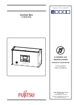
background image

Installation and 

operating manual

intended for professionals

To be saved for 

future consultation

FR

EN

IT

NL DE

Control Box

UTW-SCBYA

Document n° 1395-1 ~ 09/02/2010

Fujitsu General

 (Euro) GmbH

Werftstrasse 20

40549 Düsseldorf - Germany

Subject to modifications without notice.

Non contractual document.

Summary of Contents for UTW-SCBYA

Page 1: ... professionals To be saved for future consultation FR EN IT NL DE Control Box UTW SCBYA Document n 1395 1 09 02 2010 Fujitsu General Euro GmbH Werftstrasse 20 40549 Düsseldorf Germany Subject to modifications without notice Non contractual document ...

Page 2: ...Complies with Low voltage directive 73 23 CEE under standard EN 60335 1 Electromagnetic compatibility Diretive 89 336 CEE Installation and operating manual 1395 EN Control Box 2 ...

Page 3: ...ng the slope of heating 14 Temperature control 14 Manual adjustment 14 Self adaptation 14 Parametering the setting 16 General 16 Setting parameters 16 List of function lines settings diagnosis status 16 Configuring the installation 28 Configuration 1 2 5 or 7 29 Hydraulic connections 29 Electrical connections 29 Parametering the setting 29 Special cases 29 Electrical wiring diagram 34 Troubleshoot...

Page 4: ...nstallation and operating manual 1395 EN Control Box 4 References of heat pump Monobloc heat pump Control Box Model Output Code WPYA080LA 8 kW UTW SCBYA WPYA100LA 10 kW Optional equipment DHW kit UTW KDWXA for connecting a DHW tank with built in electrical backups Boiler connection kit UTW KBSXA for connecting a boiler to the heat pump Room thermostat UTW C55XA For correcting the ambient temperatu...

Page 5: ... 4 Control box components Front view 1 2 3 4 5 6 Back view Side view Legend 1 Start stop switch 2 User interface 3 Interface and power card 4 Regulator 5 Terminal blocks 6 DHW power relay 1 4 Description Installation and operating manual 1395 EN 5 Control Box ...

Page 6: ...heat pump program line 560 561 and 562 is set for nominal temperature from 0 00 to 5 00h and for reduced temperature for the rest of the day This optimizes electrical consumption while ensuring comfortable availability of hot water Setting for reduced temperature can be useful to prevent the DHW from switching on too often and for too long during the day The production of domestic hot water DHW is...

Page 7: ...aging The sensor must be installed in the living room area on a very uncluttered wall 1 5 m above the floor Avoid direct sources of heat chimney flue television cooking hobs draughty areas ventilation door etc Air leaks in the seals in the constructions are often translated into cold air blowing through the electrical conduits Lag the electrical conduits if there is a cold draught on the back of t...

Page 8: ...l back ups 230 V Connection to the DHW tank resistance 2 1 3 2 1 CL CL G M M B9 M BX1 CL CL QX4 N EX6 EX5 EX4 Outdoor sensor DHW sensor DHW distribution valve 5 Room thermostat ou Room control unit options External fault Tariffs day night peak times off peak times Power shedding or EJP peak day removal External component contact faults load shedder power meter If the control device does not provid...

Page 9: ...option Connect the distribution valve to connector QX4 eath and N Connect the domestic water sensor to terminal BX1 and M Conect the DHW back up to terminals 17 earth 18 and 19 Connect the back up electrical supply to terminals 14 15 and 16 earth Boiler connection Connect the distribution valve deviation boiler to the termianls 11 earth 12 and 13 Connect the boiler supply to terminals 8 9 and 10 e...

Page 10: ...ture To avoid this situation the sensor must be connected correctly Re initialise parameter 8703 commissioning level consumer diagnostic menu 2 4 Configuring room thermostat To configure the room thermostat and connect it to the appropriate heating zone Hold down the presence key for more than 3 seconds The room thermostat displays RU and a number flashes Turn the wheel to choose the zone 1 Hold d...

Page 11: ... Installation and operating manual 1395 EN 11 Control Box ...

Page 12: ...n figure 9 User interface of the control box Auto ESC OK RESET 0 4 8 12 16 20 24 1 2 3 4 5 6 7 8 9 figure 10 Room control unit option Auto ESC OK 0 4 8 12 16 20 24 1 2 3 4 5 7 12 8 6 figure 11 Room thermostat option C Auto 5 10 11 12 Installation and operating manual 1395 EN Control Box 12 ...

Page 13: ...atic Constant comfort temperature Constant reduced temperature Stand by mode with anti frost protection Provided that the heat pump s electrical power supply is not interrupted 6 Information display Various data page 35 Reading error codes Information concerning maintenance special mode 7 Confirm OK Input into the selected menu Confirmation of the parameter settings Confirmation of the adjustment ...

Page 14: ... temperature control parameter 721 modifies the initial temperature of all the curves without modification of the slope figure 13 The corrective actions in the case of any inconvenience are detailed in the table figure 14 3 2 3 Self adaptation When this function is active parameter 726 the temperature control is automatically adjusted it is therefore futile to modify the slope or the off set in th...

Page 15: ... weather Curve slope line 720 Curve off set line 721 No correction No correction No correction No correction No correction OK OK OK OK OK OK Cold Cold Cold Cold Cold Hot Hot Hot Hot Hot Hot Cold No correction Corrective actions on the temperature control 90 80 70 60 50 40 30 C 100 C 20 20 10 1 0 75 1 75 0 5 0 25 1 25 10 0 2 1 5 2 25 2 5 Boiler connection application Heat pump application only Heat...

Page 16: ...1 Hours 1 24 h Operator section Day month 2 Minutes 0 60 min Time prog heating circuit 1 Year 3 Press for 3 seconds End user Commissioning Engineer OEM Time of day and date Hours minutes 1 Operator section Day Month 2 Time prog heating circuit 1 Year 3 Start of summer time 4 01 01 31 12 End of summer time 5 Line Function Setting range or display Setting increment Basic setting Date and time 1 U Ho...

Page 17: ... is fitted with a DHW tank Only with the DHW kit option 560 U Pre selection Day Week Mon Sun Mon Fri Sat Sun Monday Tuesday Mon Sun 561 U 1st phase On start 00 00 10 min 00 00 562 U 1st phase Off end 00 00 10 min 05 00 563 U 2nd phase On start 00 00 10 min 564 U 2nd phase Off end 00 00 10 min 565 U 3rd phase On start 00 00 10 min 566 U 3rd phase Off end 00 00 10 min 576 U Default values No Yes No ...

Page 18: ...C 10 C 1 C 3 C This function enables you partially to offset the automatic summer winter switchover during the intermediate seasons Increasing the value delays the switchover to summer regime Decreasing the value advances the switchover to summer regime This function is only active in automatic mode 740 S Flow temp setpoint min for fan convectors 8 95 C 1 C 8 C 741 S Flow temp setpoint max 8 95 C ...

Page 19: ...ops automatically after running for 25 days 856 I Floor curing day current 0 32 857 I Days complete current 0 32 900 S Operating mode changeover None Protection mode Reduced Comfort Automatic 1 Protection mode Operating mode at end of concrete slab drying period Please comply with the standards and instructions of the manufacturer of the building A good performance ofthisfunctionisonlypossible wit...

Page 20: ...ode after having operated in heating mode and vice versa 918 S Summer comp start at OT 20 50 C 1 C 26 C The comfort setting 902 is increased in line with the outdoor temperature rising above this reading 919 S Summer comp end at OT 20 50 C 1 C 40 C Above this reading the comfort setting 902 is no longer affected by an increase in the outdoor temperature 920 S Summer comp setp increase 1 10 C 1 C 4...

Page 21: ...cr hygro 1 20 C 1 C 10 C 948 S Flow setp incr start at r h 0 100 1 60 950 S Flow temp diff dewpoint 0 5 C 1 C 2 C 963 S With prim contr system pump No Yes No 969 S Operating mode changeover No Off Automatic Off 30 20 18 16 C C 25 35 908 909 923 924 Flow temperature setpoint Outside temperature Flow temperature setpoint with minimum limit Flow temperature setpoint without minimum limit figure 18 Li...

Page 22: ...only authorised during off peak hours 1640 I Legionella function Off Periodic depending on the line setting 1641 Set day of the week depending on the line setting 1642 Off 1641 I Legionella funct periodically 1 to 7 1 day 7 1642 I Legionella funct weekday Monday Tuesday Saturday 1644 I Legionella funct time 00 00 23 50 If no value is entered no anti legionella cycle has been run 1645 I Legionella ...

Page 23: ...on and 1 heating circuit Pre setting 7 Boiler connection 1 heating circuit and DHW tank Pre setting 3 4 6 8 to 12 Do not use for monobloc heat pump 5711 S Cooling circuit 1 Off 4 pipe system 2 pipe system Off 4 pipe system is not compatible with the heat pump Select 2 pipe system to activate cooling operation 5870 S Combi storage tank No Yes No 5987 S Cont type input EX4 Normally closed contact NC...

Page 24: ...ult occurs error 370 On The heat pump uses the boiler connection when a fault occurs error 370 In the On position the energy costs can be onerous if the error is not eliminated 7142 S Emergency operating function type Manual Automatic Manual Manual Emergency mode is not active when a fault occurs Emergency mode OFF Automatic Emergency mode is active when a fault occurs Emergency mode ON In Automat...

Page 25: ...28 350 C 0 7833 I Sensor temperature BX22 module 2 28 350 C 0 7841 I Contact status H1 Open Closed Open 7846 I Contact status H2 Open Closed Open 7855 I Contact status H3 Open Closed Open 7914 I Input EX4 0 230 V 0 7915 I Input EX5 0 230 V 0 7916 I Input EX6 0 230 V 0 State 8000 I State heating circuit 1 0 8003 I State DHW 0 8004 I State cooling circuit 1 0 8006 I State heat pump 0 8022 I State su...

Page 26: ...50 C 8701 U Outside temp min Reset No Yes 50 50 C 8702 U Outside temp max Reset No Yes 50 50 C 8703 I Outside temp attenuated Reset No Yes 50 50 C This is the average of the outdoor temperature over a 24 hour period This value is used for automatic Summer Winter switchover line 730 8704 I Outside temp composite 50 50 C The composite outdoor temperature is a combination of the current outdoor tempe...

Page 27: ...w temperature setpoint 0 140 C 0 8957 I Common flow setpoint refrigeration 0 140 C 9031 I Relay output QX1 Off On Off 9032 I Relay output QX2 Off On Off 9033 I Relay output QX3 Off On Off 9034 I Relay output QX4 Off On Off 9035 I Relay output QX5 Off On Off 9036 I Relay output QX6 Off On Off 9037 I Relay output QX7 Off On Off 9050 I Relay output QX21 module 1 Off On Off 9051 I Relay output QX22 mo...

Page 28: ...700 Type of installation Page Pre setting 1 1 heating circuit 30 Pre setting 2 1 heating circuit and DHW tank 31 Pre setting 3 Do not use for monobloc heat pump Reserved only for 2 circuits installation Pre setting 4 Pre setting 5 Boiler connection and 1 heating circuit 32 Pre setting 6 Do not use for monobloc heat pump Reserved only for 2 circuits installation Pre setting 7 Boiler connection 1 he...

Page 29: ...10 to 1661 Adjust the heating curve slope line 720 4 1 4 Special cases Please consult us regarding any other installation configuration DHW tank control with electrical back up requires the use of the DHW kit The management of a boiler is required to install a boiler connection kit 4 1 1 Hydraulic connections In the case of a mixed DHW tank Install the distribution valve on the heating circuit in ...

Page 30: ...egulation Control Box R Radiators or fan convectors CA Room control unit or Room thermostat option SE Outdoor sensor SP Heated floor thermal safety fuse Overall hydraulic layout Overview of all the electrical connections See detailed instructions on page 28 Installation and operating manual 1395 EN Control Box 30 ...

Page 31: ...lation pump CR Regulation Control Box KS DHW kit R Radiators or fan convectors CA Room control unit or Room thermostat option SE Outdoor sensor SP Heated floor thermal safety fuse SSa DHW sensor VD Distribution valve Overall hydraulic layout Overview of all the electrical connections Configuration 2 1 heating circuit and DHW tank Installation and operating manual 1395 EN 31 Control Box ...

Page 32: ...alve CCI Heatingsystemcirculationpumpbuiltintotheboiler CC Heating circulation pump CR Regulation Control Box R Radiators or fan convectors CA Room control unit or Room thermostat option SE Outdoor sensor SDR Boiler connection valve flow sensor SP Heated floor thermal safety fuse TA Boiler supply of boiler unit VDI Distribution valve deviation boiler Ex boiler unit Ex boiler unit See detailed inst...

Page 33: ...avity feed valve CCI Heatingsystemcirculationpumpbuiltintotheboiler CC Heating circulation pump CR Regulation Control Box R Radiators or fan convectors CA Room control unit or Room thermostat option KS DHW kit SE Outdoor sensor SDR Boiler connection valve flow sensor SSa DHW sensor SP Heated floor thermal safety fuse TA Boiler supply of boiler unit VD Distribution valve VDI Distribution valve devi...

Page 34: ...ref H1 H3 X30 DO1 DO2M BX4 BX5 1 L 2 N 3 COM 4 5 6 7 8 N 9 L 10 11 12 L 13 N 14 L 15 N OUTDOOR UNIT BOILER CONNECT BOILER VALVE DHW BACK UP SUPPLY DHW BACK UP CONNECT 16 17 18 L 19 N Connections to regulator accessories and options see figure 8 page 8 Connections to terminals see figure 7 page 8 Start stop switch Installation and operating manual 1395 EN Control Box 34 ...

Page 35: ...s 369 External fault safety component No 370 Heat pump error Refer to the service manual of the heat pump No 6 2 Information display Various data can be displayed by pressing the info button Depending on the type of unit configuration and operating state some of the info lines listed below may not appear Possible error messages from the error code list Possible service messages from the maintenanc...

Page 36: ...ent than default values 1610 1612 3 Start a legionella cycle 1640 1647 4 Perform floor drying 850 857 7 2 Start up check list 7 2 1 Before starting up Sight checks Heat pump OK Non compliant Location and fittings condensate evacuation Compliance with distances from obstacles Hydraulic checks OK Non compliant Value Connection of pipes valves and pumps 1 circuit DHW Installation water volume expansi...

Page 37: ...After a few minutes measurement of air temp delta Check condensation and evaporation pressure temperature After 15 mins of operation Primary water temp delta DHW priority switching of selection valve Operation of heating mixing valve boiler backup Control settings Room control see chapiter Configuring the room thermostat page 10 OK Non compliant Settings manipulations checks Setpoint display Expla...

Page 38: ...kup 3700 OT switch on authoris addit gen 3705 swith off delay addit gen Miscellaneous 6046 input H2 function 9 configuration 6100 OT sensor correction configuration 6120 frost protection on off configuration 6205 reset settings configuration 6220 software version configuration 6711 reset heat pump error 7070 to 7183 maintenance maintenance 7700 to 7916 input output testing I O testing 8402 to 8457...

Page 39: ...ation C Water input temperature C ΔT secondary C Evaporation temperature LP bar C Suction temperature C Overheating C Battery air input temperature C ΔT evaporation C Battery air output temperature C ΔT battery C Hydraulic system of hydraulic unit Secondary system Low temp heating floor Circulator brand Type LT Radiators Circulator brand Type fan coils Domestic hot water tank type Circulator brand...

Page 40: ...is appliance also conforms to Regulation 842 2006 of the european parliament on certain fluorinated greenhouse gases The standards relating to the product and the testing methods used Air conditioners refrigeration units and heat pumps with compressor driven by electric motor for heating and refrigeration EN 14511 1 14511 2 14511 3 and 14511 4 To standard XP ENV 12102 Air conditioners heat pumps a...

Reviews: