background image


Rev.9 EM073C1492F

ROBOT CONTROLLER


RC420


Summary of Contents for RC420

Page 1: ...Rev 9 EM073C1492F ROBOT CONTROLLER RC420 ...

Page 2: ...ROBOT CONTROLLER RC420 Rev 9 ...

Page 3: ...RC420 Rev 9 i ROBOT CONTROLLER RC420 Rev 9 Copyright 2002 2007 SEIKO EPSON CORPORATION All rights reserved ...

Page 4: ...for warranty period information However customers will be charged for repairs in the following cases even if they occur during the warranty period 1 Damage or malfunction caused by improper use which is not described in the manual or careless use 2 Malfunctions caused by customers unauthorized disassembly 3 Damage due to improper adjustments or unauthorized repair attempts 4 Damage caused by natur...

Page 5: ...y to Windows 2000 and Windows XP NOTICE No part of this manual may be copied or reproduced without authorization The contents of this manual are subject to change without notice Please notify us if you should find any errors in this manual or if you have any comments regarding its contents INQUIRIES Contact the following service center for robot repairs inspections or adjustments If service center...

Page 6: ...266 61 1802 FAX 81 0 266 61 1846 SUPPLIERS North South America EPSON AMERICA INC Factory Automation Robotics 18300 Central Avenue Carson CA 90746 USA TEL 1 562 290 5900 FAX 1 562 290 5999 E MAIL info robots epson com Europe EPSON DEUTSCHLAND GmbH Factory Automation Division Otto Hahn Str 4 D 40670 Meerbusch Germany TEL 49 0 2159 538 1391 FAX 49 0 2159 538 3170 E MAIL robot infos epson de ...

Page 7: ...ble Connection 24 3 3 2 Connecting the Manipulator to the Controller 27 3 4 Noise Countermeasures 28 4 OPTIONAL DEVICE Connector 29 4 1 OPTIONAL DEVICE Connector 29 4 2 ATTEND TEACH Control Device 30 4 3 OPTIONAL DEVICE Dummy Plug 31 4 4 Pin Assignments 32 5 EMERGENCY Connector 33 5 1 Safety Door Switch and Latch Release Switch 33 5 1 1 Safety Door Switch 33 5 1 2 Latch Release Switch 34 5 1 3 Che...

Page 8: ...ircuit 56 7 4 Expansion I O Board Pin Assignments 58 7 4 1 Pin Assignments NPN type 58 7 4 2 Pin Assignments PNP type 60 7 5 Expansion I O Connector 62 7 5 1 Pin Layout of Expansion I O Connector 62 7 5 2 Expansion I O Connector Cable 62 7 5 3 Cable Pin Assignments 63 8 I O Remote Settings 67 8 1 I O Signal Description 68 8 1 1 Remote Input Signals 68 8 1 2 Remote Output Signals 71 8 2 Timing Spec...

Page 9: ...ure 98 10 6 4 UPS Setup Consideration 102 Maintenance 1 Safety Precautions on Maintenance 107 1 1 Safety Precautions 107 1 2 Lockout 108 1 3 Tagout 108 2 Regular Maintenance Inspection 109 2 1 Schedule for Maintenance Inspection 109 2 2 Inspection Point 109 2 2 1 Inspection While the Controller is Turned OFF 109 2 2 2 Inspection While the Controller is Turned ON 109 2 3 Cleaning the Fan Filter 109...

Page 10: ...he HDD 143 12 1 Recovering Windows 144 12 1 1 Recovery Procedure 144 12 1 2 Windows Recovery With EasyRestore License Label 144 12 1 3 Windows Recovery Without EasyRestore License Label 147 12 2 Configuring Windows 151 12 3 Setting Up EPSON RC Using the Network 151 12 3 1 Necessary Items 151 12 3 2 Sharing Configuration 151 12 3 3 Network Configuration 153 12 3 4 Starting EPSON RC Setup Program 15...

Page 11: ...Setup Operation This manual contains information for setup and operation of the RC420 Robot Controller ...

Page 12: ...Setup Operation ...

Page 13: ...equirements 1 1 Conventions Important safety considerations are indicated throughout the manual by the following symbols Be sure to read the descriptions shown with each symbol WARNING This symbol indicates that a danger of possible serious injury or death exists if the associated instructions are not followed properly WARNING This symbol indicates that a danger of possible harm to people caused b...

Page 14: ...ct has been designed and manufactured strictly for use in a normal indoor environment Using the product in an environment that exceeds the specified environmental conditions may not only shorten the life cycle of the product but may also cause serious safety problems The robot system must be used within the installation requirements described in the manuals Using the robot system outside of the in...

Page 15: ...o connect the cables properly Do not allow unnecessary strain on the cables Do not put heavy objects on the cables Do not bend or pull the cables forcibly The unnecessary strain on the cables may result in damage to the cables disconnection and or contact failure Damaged cables disconnection or a contact failure is extremely hazardous and may result in electric shock and or improper function of th...

Page 16: ...s or wiring press the Emergency Stop switch immediately to stop the Manipulator The following items are safety precautions for qualified operator personnel WARNING The interlock of the Safety Door must be functioning when the robot system is operated Do not operate the system under the condition that the switch cannot be turned ON OFF I E the condition where the switch is disabled Example Tape is ...

Page 17: ...ped with the Emergency Stop switch The EMERGENCY connector on the Controller has expansion Emergency Stop input terminals used for connecting the Emergency Stop switches These Emergency Stop inputs are internally connected to the relays for the dynamic brake Therefore pressing any Emergency Stop switch can shut off the motor power immediately and the robot system will enter the Emergency Stop cond...

Page 18: ...ory check sum error and overheat condition inside the Motor Driver Module Encoder Cable Disconnection Error Detection The dynamic brake circuit is activated when the Motor Encoder Signal cable is disconnected Motor Overload Detection The dynamic brake circuit is activated when the system detects that the load on the motor has exceeded its capacity Irregular Motor Torque out of control manipulator ...

Page 19: ...tected the dynamic brake circuit is activated Memory Check sum Error Detection The dynamic brake circuit is activated when a memory check sum error is detected Overheat Detection at the Motor Driver Module The dynamic brake circuit is activated when the temperature of the power device inside the Motor Driver module is above the nominal limit Over Voltage Detection The dynamic brake circuit is acti...

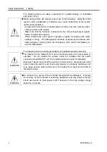
Page 20: ...Setup Operation 1 Safety 10 RC420 Rev 9 ...

Page 21: ...ore Controllable Axes Up to four 4 connectable AC Servo Motors Programming Language and Robot Control Software EPSON RC a multi tasking robot language Joint Control Simultaneous control over all the four 4 joints Software AC servo control Speed Control PTP motion Programmable in the range of 1 to 100 CP motion Programmable Actual value to be manually entered Robot Manipulator Control Acceleration ...

Page 22: ... Safety door input Low power mode Dynamic brake Encoder cable disconnection error detection Motor overload detection Irregular motor torque out of control Manipulator detection Motor speed error detection Positioning overflow servo error detection Speed overflow servo error detection CPU irregularity detection Memory check sum error detection Overheat detection at the Motor Driver Module Safety ke...

Page 23: ...ed for the robot system If any other hardware is installed to the robot system the robot system may not only function improperly but also cause safety problems For EPSON RC Users only the hardware that has been approved by EPSON can be installed on the robot system CAUTION Do not install any other software in the robot system except for the software that was originally installed at ship time If an...

Page 24: ...0 4 sec 0 4 sec Joint number in 2 digits Manipulator number in 2 digits Error number in 4 digits 1 sec The above mentioned cycle which lasts approximately 10 seconds repeats and is displayed until the error is canceled or the power is OFF Error Number Four digit error numbers are displayed For details refer to the error number table in the chapter SPEL Error Messages in SPEL Language Reference Man...

Page 25: ...oller is turned ON SAFE SHUTDOWN Lights when it is safe to turn OFF the Controller 4 Connection Check label The details of the Manipulator to be connected are recorded on the label as shown below The label indicates the Manipulator model and Manipulator serial number Example MANIPULATOR 00002 ES551S 5 Windows COA label The Product Key that is required when you install Windows is recorded on this l...

Page 26: ...SON RC software key to the IEEE 1284 parallel connector on the rear of the Controller 11 Cooling Fan Filter A protective filter is installed in front of the cooling fan to filter out dust Check condition of the filter regularly and clean it as necessary A dirty filter may result in the malfunction of the robot system as the temperature rises in the Controller The filter needs regular check up and ...

Page 27: ...9 12 14 15 16 11 1 1 M C POWER connector A connector for the Manipulator power source Connect the dedicated power cable attached to the Manipulator 2 USB connector Connects the USB enabled hardware CD ROM drive etc There is another port on the front of the Controller 3 IEEE 1284 parallel connector This connector is for the EPSON RC software key 4 EMERGENCY connector This connector is used for inpu...

Page 28: ...ard For details refer to the Setup Operation 2 2 Standard Specifications The CPU board has different model numbers and appearances depending on the dates of the shipping and the board changeover CPU Board Connector for Mouse and Keyboard 11 1 PC 686BX PC EPC850 Separate connectors 11 2 SPI 6941 EPC Integrated connector 12 Ethernet connector This Ethernet connector is used for network communication...

Page 29: ...etup Operation 2 3 Controller Part Names and Functions RC420 Rev 9 19 2 3 3 Dimensions 383 0 483 0 433 0 9 9 470 0 189 0 12 0 101 6 415 0 35 0 Unit mm Do not remove any rubber feet of the Controller NOTE ...

Page 30: ...Setup Operation 2 3 Controller Part Names and Functions 20 RC420 Rev 9 ...

Page 31: ...out mouse and keyboard Electrostatic noise 6 kV or less without mouse and keyboard Environment Install indoors only Place in a well ventilated area Keep away from direct sunlight Keep away from dust oily smoke oily mist salinity metal powder or other contaminants Keep away from flammable or corrosive liquid and gas Keep away from water Keep away from shocks or vibrations Keep away from sources of ...

Page 32: ... to determine total consumption Rated consumption 200 W total Manipulator consumption rated 1 2 Peak Current When power is turned ON approximately 50A 2msec When motor is ON approximately 150A 5msec Leakage Current Max 3 5 mA Ground Resistance 100 Ω or less Install an earth leakage circuit breaker or a circuit breaker in the AC power cable line at 20A or less rated electric current Both should be ...

Page 33: ...al AC power Blue W terminal Protective earth wire Green Yellow 3 3 Cable Connection Make sure that the power to the Controller is turned OFF and locked out before connecting or disconnecting any cables Connecting or disconnecting any cables with the power ON is extremely hazardous and may result in electric shock and malfunction of the Controller WARNING Be sure to connect the cables properly Do n...

Page 34: ...the shipping and the board changeover Separate connectors for mouse and keyboard Manipulator M C POWER M C SIGNAL STANDARD I O EMERGENCY INPUT Protective Earth Terminal Expansion I O option MONITOR MOUSE KEYBOARD OPTIONAL DEVICE 1 M C Power Cable 2 M C Signal Cable 3 STANDARD I O 4 EMERGENCY 5 AC Power Cable 6 Protective Earth Input output unit E STOP switch Safety Door switch AC200V power Protect...

Page 35: ... Terminal Expansion I O option MONITOR MOUSE KEYBOARD OPTIONAL DEVICE 1 M C Power Cable 2 M C Signal Cable 3 STANDARD I O 4 EMERGENCY 5 AC Power Cable 6 Protective Earth Input output unit E STOP switch Safety Door switch AC200V power Protective earth Input output unit Monitor Mouse Keyboard ATTEND TEACH Control Device or Operation Unit or Dummy Plug 7 Controller 10 Mouse Keyboard Cable ...

Page 36: ...le Cables for AC 200V or the local equivalent power supply to the Controller 6 Protective Earth Terminal connector The Protective Earth terminal connects to the earth ground wire The Protective Earth terminal is better to be connected when a peripheral control unit such as a sequencer is used in the system Use a cable of size equal to or greater than AWG 16 for the Protective Earth terminal 7 OPTI...

Page 37: ...damage to the cables disconnection and or contact failure Damaged cables disconnection or contact failure is extremely hazardous and may result in electric shock and or improper function of the system CAUTION The serial number of the Manipulator that should be connected is indicated on the Connection Check Label on the Controller Connect the Controller and the Manipulator correctly Improper connec...

Page 38: ...O lines and do not bundle both sets of wiring with the same cable tie If more than one duct cable must cross each other they should cross perpendicularly The preferable example is shown in the right figure AC Line duct DC line duct 200 mm or more For I O lines wire as short as possible and use a shielded cable and clamp the shield to the attached connector interior Use a shielded cable for the EME...

Page 39: ... OPTIONAL DEVICE connector while the Controller is ON may cause damage to the EPSON RC software key Connect the EPSON RC software key to the IEEE 1284 parallel connector on the rear of the Controller The OPTIONAL DEVICE connector is used for an optional operation unit ATTEND TEACH control device or OPTIONAL DEVICE Dummy Plug The OPTIONAL DEVICE Dummy Plug an accessory that comes with the Controlle...

Page 40: ...E connector Emergency Stop switch 3 position enable switch dead man switch ATTEND TEACH control device enable disable switch Refer to the following the figure for the internal circuit and refer to the Setup Operation 4 4 Pin Assignments for the signal OPTIONAL DEVICE ATTEND TEACH Control Device Connector E_SW11 E_SW21 E_SW12 E_SW22 SG ENABLE SG KEY1 KEY2 6 9 10 11 13 14 15 18 19 EStop Switch 3 Pos...

Page 41: ...he dummy plug as shown below to disable the Emergency Stop input for the OPTIONAL DEVICE port and the ATTEND TEACH control device enable disable input In this case however you cannot operate the Manipulator while the safety door is open When designing and manufacturing robotic systems follow the descriptions of the Safety chapter in EPSON RC User s Guide OPTIONAL DEVICE OPTIONAL DEVICE Dummy Plug ...

Page 42: ...ot to be used 17 Not to be used 5 Not to be used 18 KEY1 6 E_SW11 19 KEY2 7 SG 20 Not to be used 8 Not to be used 21 Not to be used 9 E_SW21 22 Not to be used 10 E_SW12 23 Not to be used 11 E_SW22 24 Not to be used 12 Not to be used 25 12V 13 SG Each mode is dictated by the signals at KEY1 and KEY2 as follows Operation Condition KEY1 KEY2 Enabled Connect to SG 13 pin Open The ATTEND TEACH control ...

Page 43: ...ion In order to maintain a safe working zone a safeguard must be erected around the Manipulator The safeguard must have an interlock switch at the entrance to the working zoon The Safety Door that is described in this manual is one of the safeguards and an interlock of the Safety Door is called a Safety Door switch Connect the Safety Door switch to the Safety Door input terminal on the EMERGENCY c...

Page 44: ...e sure to check the switch operation for safety by following the procedures described below before operating the Manipulator 1 Turn ON the Controller while the safety door is open in order to boot the controller software 2 Make sure that Safety is displayed on the main window status bar 3 Close the safety door and turn ON the switch connecting to the latch release input Make sure that the Safety i...

Page 45: ... or more the system recognizes it as a critical error Therefore make sure that the Emergency Stop switch has double contacts and that each circuit connects to the specified pins on the EMERGENCY connector at the Controller Refer to the Setup Operation 5 5 Circuit Diagrams 5 2 2 Checking Emergency Stop Switch Operation Once the Emergency Stop switch is connected to the EMERGENCY connector continue ...

Page 46: ...the Safety Door switch or Emergency Stop switch to the EMERGENCY connector remove the E STOP box from the connector E STOP Box Cable 4 m Connect to EMERGENCY connector 5 3 2 Checking E STOP Box Operation Once the E STOP box is connected to the EMERGENCY connector continue the following procedure to make sure that the E STOP box functions properly For the safety of the operator the Manipulator must...

Page 47: ... occurs if the input values from the Safety Door 1 and Safety Door 2 are different for two or more seconds They must be connected to the same switch with two sets of contacts 3 The signal from the Emergency Stop switch is designed to use two redundant circuits An error occurs if the statuses of the two redundant circuits are different for two or more seconds They must be connected to the same swit...

Page 48: ...24V External 24V Safety Door input 2 Latch release input Latch release input Close latch off Open latch on Emergency Stop switches of an operation unit External 24V GND 9 19 1 2 11 12 3 13 5 6 4 14 10 20 8 7 18 17 16 15 Dynamic brake control External Emergency Stop switches Controller Safety Door input 1 Dynamic brake control Emergency Stop detection Emergency Stop detection Emergency Stop detecti...

Page 49: ...ove diagram is simplified for representation Dynamic brake relay of motor driver 24V 24V Safety Door input 1 External 24V Latch release input 9 Safety Door latch release input Close latch off Open latch on Emergency stop detection Dynamic brake control Emergency Stop switches of an operation unit 19 1 2 11 12 3 13 5 6 4 14 10 20 8 7 18 17 16 15 External 24V GND External 24V External 24V GND Extern...

Page 50: ...Setup Operation 5 5 Circuit Diagrams EMERGENCY Connector 40 RC420 Rev 9 ...

Page 51: ...put equipment to the system It has pins for 16 inputs and 16 outputs The STANDARD I O corresponds to the input output bit numbers 0 15 Refer to the Setup Operation 7 Expansion I O Board Optional for the specified model of an expansion I O Board For cable wiring refer to the Setup Operation 3 4 Noise Countermeasures in order to prevent noise ...

Page 52: ...rrectly Improper wiring may cause safety problems as it may make the Manipulator move unusually CAUTION When the wiring for PNP or NPN type is changed the jumper settings don t require changing Typical Input Circuit Application 1 NPN I O 1 Same Omit GND DC 1 Input No 0 to 7 common 2 Input No 0 3 Input No 1 4 Input No 2 5 Input No 3 10 Input No 8 to 15 common 11 Input No 8 12 Input No 9 6 Input No ...

Page 53: ...cal Input Circuit Application 2 PNP I O 1 Same Omit GND DC 1 Input No 0 to 7 common 2 Input No 0 3 Input No 1 4 Input No 2 5 Input No 3 10 Input No 8 to 15 common 11 Input No 8 12 Input No 9 6 Input No 4 7 Input No 5 8 Input No 6 9 Input No 7 Same Same Same Same Same Same Same ...

Page 54: ...iring diagram for CE conformance Be sure to wire correctly Improper wiring may cause safety problems as it may make the Manipulator move unusually Typical Output Circuit Application 1 NPN I O 1 Same L Load L GND DC Omit 19 Output No 0 20 Output No 1 21 Output No 2 22 Output No 3 23 Output No 4 24 Output No 5 25 Output No 6 26 Output No 7 28 Output No 8 29 Output No 9 44 Output common GND 45 Output...

Page 55: ...pplication 2 PNP I O 1 Same L Load L GND DC Omit 19 Output No 0 20 Output No 1 21 Output No 2 22 Output No 3 23 Output No 4 24 Output No 5 25 Output No 6 26 Output No 7 28 Output No 8 29 Output No 9 44 Output common DC 45 Output common DC 46 Output common DC Same Same Same Same Same Same Same Same ...

Page 56: ... 11 8 Input No 6 33 NC 9 Input No 7 34 Output No 12 10 Input common No 8 to 15 35 NC 11 Input No 8 36 Output No 13 12 Input No 9 37 NC 13 Input No 10 38 Output No 14 14 Input No 11 39 NC 15 Input No 12 40 NC 16 Input No 13 41 Output No 15 17 Input No 14 42 NC 18 Input No 15 43 NC 19 Output No 0 44 Output common 20 Output No 1 45 Output common 21 Output No 2 46 Output common 22 Output No 3 47 24V O...

Page 57: ...5 Input No 3 30 NC 6 Input No 4 31 Output No 10 7 Input No 5 32 Output No 11 8 Input No 6 33 NC 9 Input No 7 34 Output No 12 10 Input common No 8 to 15 35 NC 11 Input No 8 36 Output No 13 12 Input No 9 37 NC 13 Input No 10 38 Output No 14 14 Input No 11 39 NC 15 Input No 12 40 NC 16 Input No 13 41 Output No 15 17 Input No 14 42 NC 18 Input No 15 43 NC 19 Output No 0 44 Output common 20 Output No 1...

Page 58: ...Setup Operation 6 3 Pin Assignments STANDARD I O Connector 48 RC420 Rev 9 ...

Page 59: ...d I O 48 to 79 48 to 79 The 1st Expansion I O board 80 to 111 80 to 111 The 2nd Expansion I O board The types of the optional expansion I O board are listed below Board Name Input Output Type Output Circuit Overcurrent Protection Protected Expansion I O board NPN Hybrid IC SEP007 Available Protected Expansion I O board PNP Hybrid IC SEP008 Available Expansion I O board NPN Transistor array and pho...

Page 60: ... A14 15 16 A15 1 700 Short Short Short Short Short 2 710 Short Short Short Short Short 3 720 Short Short Short Short Short 4 730 Short Short Short Short Short JP 2 Board Address 1 2 A3 3 4 A4 5 6 A5 7 8 A6 9 10 A7 1 700 Short Short Short Short Short 2 710 Short Short Short Short 3 720 Short Short Short Short 4 730 Short Short Short Short Short circuit Blank Open JP3 Short circuit 1 2 4 5 7 8 and 1...

Page 61: ...ntroller software settings Input Voltage Range 12 V to 24 V 10 ON Voltage 10 8 V Min OFF Voltage 5 V Max Input Current 10 mA TYP at 24 V input CAUTION Use the PNP type of wiring diagram for CE conformance Be sure to wire correctly Improper wiring may cause safety problems as it may make the Manipulator move unusually Protected Expansion I O Board Typical Input Circuit Application 1 NPN Same Same S...

Page 62: ...al 52 RC420 Rev 9 Protected Expansion I O Board Typical Input Circuit Application 2 PNP Same Same Same Same Same Omit GND DC 1 Input No 48 to 51 common 3 Input No 48 4 Input No 49 5 Input No 50 6 Input No 51 51 Input No 52 to 55 common 53 Input No 52 54 Input No 53 2 2 kΩ 470 Ω ...

Page 63: ...gs CAUTION Use the PNP type of wiring diagram for CE conformance Be sure to wire correctly Improper wiring may cause safety problems as it may make the Manipulator move unusually Protected Expansion I O Board Typical Output Circuit Application 1 NPN Same Same Same Same 27 Output No 48 28 Output No 49 29 Output No 50 30 Output No 51 77 Output No 52 25 Output No 48 to 51 common DC 26 Output No 48 to...

Page 64: ... Application 2 PNP Same Same Same Same 27 Output No 48 28 Output No 49 29 Output No 50 30 Output No 51 77 Output No 52 25 Output No 48 to 51 common GND 26 Output No 48 to 51 common DC L L GND DC Omit Rated Output Voltage 12 V to 24 V 10 Maximum Output current 250 mA 1 output Output Driver P channel power MOS FET Saturation Voltage 1 0 V or under ...

Page 65: ... Short 4 730 Short Short Short Short Short JP 2 Board Address 1 2 A3 3 4 A4 5 6 A5 7 8 A6 9 10 A7 1 700 Short Short Short Short Short 2 710 Short Short Short Short 3 720 Short Short Short Short 4 730 Short Short Short Short Short circuit Blank Open JP3 Short circuit 1 2 4 5 7 8 and 10 11 JP4 5 6 Normally open When an Expansion I O Board is used the appropriate software settings must be done in add...

Page 66: ...m the first point in among the 32 points in a board CAUTION Be sure to wire the output circuit properly because it has no protection circuitry for short circuit and reverse connection Improper wiring may cause malfunction of the parts on the board and then improper function of the robot system Same Same Same Same 27 Output No 48 28 Output No 49 29 Output No 50 30 Output No 51 77 Output No 52 25 Ou...

Page 67: ...s no protection circuitry for short circuit and reverse connection Improper wiring may cause malfunction of the parts on the board and then improper function of the robot system Same Same Same Same Same 33 Output No 56 35 Output No 58 34 Output No 57 36 Output No 59 83 Output No 60 32 Output No 56 to 59 common 84 Output No 61 L L GND DC L Omit Rated Output Voltage 12 V to 24 V 10 Maximum Output Cu...

Page 68: ...n C No 56 to 59 32 Output common C GND No 56 to 59 8 NC 33 Output No 56 9 Input No 56 34 Output No 57 10 Input No 57 35 Output No 58 11 Input No 58 36 Output No 59 12 Input No 59 37 Output common E DC No 64 to 67 13 Input common E No 64 to 67 38 Output common E GND No 64 to 67 14 NC 39 Output No 64 15 Input No 64 40 Output No 65 16 Input No 65 41 Output No 66 17 Input No 66 42 Output No 67 18 Inpu...

Page 69: ...60 to 63 58 NC 83 Output No 60 59 Input No 60 84 Output No 61 60 Input No 61 85 Output No 62 61 Input No 62 86 Output No 63 62 Input No 63 87 Output common F DC No 68 to 71 63 Input common F No 68 to 71 88 Output common F GND No 68 to 71 64 NC 89 Output No 68 65 Input No 68 90 Output No 69 66 Input No 69 91 Output No 70 67 Input No 70 92 Output No 71 68 Input No 71 93 Output common H DC No 76 to 7...

Page 70: ...utput common C DC No 56 to 59 8 NC 33 Output No 56 9 Input No 56 34 Output No 57 10 Input No 57 35 Output No 58 11 Input No 58 36 Output No 59 12 Input No 59 37 Output common E GND No 64 to 67 13 Input common E No 64 to 67 38 Output common E DC No 64 to 67 14 NC 39 Output No 64 15 Input No 64 40 Output No 65 16 Input No 65 41 Output No 66 17 Input No 66 42 Output No 67 18 Input No 67 43 Output com...

Page 71: ...0 to 63 58 NC 83 Output No 60 59 Input No 60 84 Output No 61 60 Input No 61 85 Output No 62 61 Input No 62 86 Output No 63 62 Input No 63 87 Output common F GND No 68 to 71 63 Input common F No 68 to 71 88 Output common F DC No 68 to 71 64 NC 89 Output No 68 65 Input No 68 90 Output No 69 66 Input No 69 91 Output No 70 67 Input No 70 92 Output No 71 68 Input No 71 93 Output common H GND No 76 to 7...

Page 72: ...ctor 50 1 100 51 Internal power is not connected to the Expansion I O connector Therefore an external power source must be supplied 7 5 2 Expansion I O Connector Cable The Expansion I O connector cable is an optional part It has a 100 pin connector on one end and two 50 pin connectors on the other end Expansion I O board 100 pin 50 pin 2 1 2 2 m 3 4 NOTE ...

Page 73: ...ND No 52 to 55 9 53 Input No 52 34 77 Output No 52 10 54 Input No 53 35 78 Output No 53 11 55 Input No 54 36 79 Output No 54 12 56 Input No 55 37 80 Output No 55 13 7 Input common C No 56 to 59 38 31 Output common C DC No 56 to 59 14 8 NC 39 32 Output common C GND No 56 to 59 15 9 Input No 56 40 33 Output No 56 16 10 Input No 57 41 34 Output No 57 17 11 Input No 58 42 35 Output No 58 18 12 Input N...

Page 74: ... No 68 34 89 Output No 68 10 66 Input No 69 35 90 Output No 69 11 67 Input No 70 36 91 Output No 70 12 68 Input No 71 37 92 Output No 71 13 19 Input common G No 72 to 75 38 43 Output common G DC No 72 to 75 14 20 NC 39 44 Output common G GND No 72 to 75 15 21 Input No 72 40 45 Output No 72 16 22 Input No 73 41 46 Output No 73 17 23 Input No 74 42 47 Output No 74 18 24 Input No 75 43 48 Output No 7...

Page 75: ...No 52 34 77 Output No 52 10 54 Input No 53 35 78 Output No 53 11 55 Input No 54 36 79 Output No 54 12 56 Input No 55 37 80 Output No 55 13 7 Input common C No 56 to 59 38 31 Output common C GND No 56 to 59 14 8 NC 39 32 Output common C DC No 56 to 59 15 9 Input No 56 40 33 Output No 56 16 10 Input No 57 41 34 Output No 57 17 11 Input No 58 42 35 Output No 58 18 12 Input No 59 43 36 Output No 59 19...

Page 76: ... No 68 34 89 Output No 68 10 66 Input No 69 35 90 Output No 69 11 67 Input No 70 36 91 Output No 70 12 68 Input No 71 37 92 Output No 71 13 19 Input common G No 72 to 75 38 43 Output common G GND No 72 to 75 14 20 NC 39 44 Output common G DC No 72 to 75 15 21 Input No 72 40 45 Output No 72 16 22 Input No 73 41 46 Output No 73 17 23 Input No 74 42 47 Output No 74 18 24 Input No 75 43 48 Output No 7...

Page 77: ...this manual For details about communication with external equipment refer to the chapter Remote Control in EPSON RC User s Guide CAUTION When using remote I O always make sure of the following Using the robot system under unsatisfactory conditions may cause malfunction of the system and or safety problems Assign remote functions to inputs outputs correctly and wire correctly when setting up remote...

Page 78: ...bled when tasks are running PowerHigh Sets high motor power mode for the current robot The motors must be on and the PowerLow input must be off Disabled when tasks are running PowerLow Turns off high power mode for the current robot and disables PowerHigh Disabled when tasks are running Mcal Executes MCal command Disabled when tasks are running Home Executes Home command Disabled when tasks are ru...

Page 79: ... are running Reboot Reboots the Controller Disabled when tasks are running 1 The SelRobot input is used to select the Manipulator for executing Motor Mode Power Mode MCALComplete AtHOME the output of CurrRobot0 to 3 for remote output and Motor ON Motor OFF Mcal Home for remote input 2 The Start input is enabled for the group number specified with SelGroup0 3 bits 3 Specify the manipulator number w...

Page 80: ...roup number with SelGroup0 3 referring to the table below Specified Group No SelGroup0 SelGroup1 SelGroup2 SelGroup3 1 0 0 0 0 2 1 0 0 0 3 0 1 0 0 4 1 1 0 0 5 0 0 1 0 6 1 0 1 0 7 0 1 1 0 8 1 1 1 0 9 0 0 0 1 10 1 0 0 1 11 0 1 0 1 12 1 1 0 1 13 0 0 1 1 14 1 0 1 1 15 0 1 1 1 16 1 1 1 1 0 OFF 1 ON ...

Page 81: ...n error had occurred You must execute a Reset input to clear the error condition AutoMode Indicates that remote input commands will be accepted TeachMode Indicates that the system is in Teach mode EnableOn Indicates that the enable switch dead man is on during Teach mode CurrRobor0 Robot Bit 0 weight 1 3 CurrRobor1 Robot Bit 1 weight 2 3 CurrRobor2 Robot Bit 2 weight 4 3 CurrRobor3 Robot Bit 3 wei...

Page 82: ...as well as CPU speed of the Controller Check carefully and refer to the following charts for the timing interrelation when you enter an input signal During system design make sure that you actuate only one remote input operation at a time otherwise an error will occur The pulse width of an input signal must be 25 or more milliseconds to be detected 8 2 2 Timing Diagram for Operation Execution Sequ...

Page 83: ...quence CurrGroup Output CmdRunning Output TasksRunning Output Paused Output 1 20 20 20 20 20 10 10 30 10 10 60 34 600 600 SelGroup Input Start Input Pause Input Cont Input AbortAll Input 40 Unit msec 1 The duration varies depending on the Quick Pause QP setting and the program s operating status at the time of Pause input ...

Page 84: ...y Door Input Sequence Paused Output MotorOn Output Safety Input Input Latch Input Input 10 SafeGuard Output Cont Input 30 10 600 Depending on Program Unit msec 8 2 5 Timing Diagram for Emergency Stop Sequence TasksRunning Output MotorOn Output 60 EStopOn Output Emergency Input Reset Input 10 10 50 Unit msec ...

Page 85: ...e Settings RC420 Rev 9 75 8 2 6 Timing Diagram for RECOVER Sequence Remote Auto Recover Paused Output SafeGuard Output RecoverReqd Output RecoverInCycle Output Safety Input Input Latch Input Input Recover Input Start Input 22 6 21 25 20 18 11 Unit msec ...

Page 86: ...ifications I O Remote Settings 76 RC420 Rev 9 Remote Manual Recover Paused Output SafeGuard Output RecoverReqd Output RecoverInCycle Output Safety Input Input Latch Input Input Recover Input Start Input 22 6 21 25 20 18 11 Unit msec ...

Page 87: ...ler The user must prepare them as necessary Connector Standard Communication connector D sub 9 pin 4 40 screw The cable must be shielded twisted pair Clamp the shield to the connector hood to prevent noise 9 1 1 Pin Assignments Pin assignments for RS 232C connectors are as follows Pin No Abbr Signal Name Signal Direction 1 CD Data carrier detect Input 2 RD Receive data Input 3 SD Send data Output ...

Page 88: ...ol Controller Peripheral equipment Signal Name Pin No Pin No Signal Name SD 3 2 SD RD 2 3 RD SG 5 7 SG RS 7 4 RS CS 8 5 CS DR 6 6 DR CD 1 8 CD ER 4 20 ER Clamp Hood 1 FG 9 2 Preparation for Communication For communication via RS 232C between the Controller and peripheral equipment to work the port configuration on both units must be the same For details on the set up procedure and communication co...

Page 89: ... 5V and 12V power supplies that are necessary to operate the CPU and hard disk The UPS does not back up the power for the Manipulator or Encoder Power Supply Therefore when a power failure or power off without shutdown occurs while the Manipulator is operating an error such as an encoder cable disconnection error occurs and the Manipulator makes an emergency stop 10 3 Normal Shutdown of Robot Syst...

Page 90: ...ccurs The power recovers during the automatic shutdown The power switch is turned OFF accidentally The power switch is turned ON during the automatic shutdown The UPS automatically shuts down Windows when detecting power off Once the shutdown is started the shutdown cannot be stopped even though the power failure condition has been corrected After Windows is shut down the SHUTDOWN LED on the front...

Page 91: ...rging Battery Turning ON the Controller will automatically charge the UPS battery It takes approximately 80 minutes to completely charge a discharged UPS battery To charge the battery fully turn ON the Controller and keep it energized continuously 10 5 3 Life Cycle of Battery The life cycle of the battery depends on the ambient temperature number of backup cycles current carrying capacity during b...

Page 92: ...zed for approximately 80 minutes 2 From the Windows 2000 task bar click the Start button and select the Settings Control Panel The Control Panel window will appear 3 Double click the System icon in the Control Panel window to show the System Properties dialog Then click the Hardware tab 4 Click the Device Manager button to show the Device Manager dialog 5 Select the SPEL RESOURCE Drivers SPEL VSRC...

Page 93: ...t cover from the Controller 4 Remove the battery connector 5 Remove six mounting screws and remove the battery cover 6 Pull out the battery from the Controller 7 Remove the U shaped plate from the front of the battery and mount it onto a new battery U shaped Plate 8 Insert the new battery into the Controller 9 Secure the battery cover to the Controller with the six mounting screws 10 Connect the b...

Page 94: ...Controller you must configure COM4 to allow communication with the device and also install the UPS driver following the procedure below The installation procedure differs according to the version of the EPSON RC NOTE EPSON RC 4 1 or before Windows 2000 1 Restart the Controller and enter the BIOS 2 In the PCI configuration set IRQ11 to Legacy This will reserve IRQ11 for COM4 3 Reboot the Controller...

Page 95: ...e Power Supply 7 Select the Add a new device then click the Next button 8 Select the No I want to select the hardware from a list option button then click the Next button 9 Select the Ports COM LPT then click the Next button RC420 Rev 9 85 ...

Page 96: ...ll receive a warning message Windows could not detect settings Ignore the message and click the OK button 12 Select Basic configuration 0008 in the Setting based on box in the Add New Hardware Wizard Properties dialog 13 Click the Input Output Range in the Resource settings box in the Add New Hardware Wizard Properties dialog 86 RC420 Rev 9 ...

Page 97: ...e Wizard Properties dialog 17 Click the Change Setting button in the Add New Hardware Wizard Properties dialog The Edit Interrupt Request dialog will appear 18 Enter 11 for the Value box and click the OK button 19 Click the Next button in the wizard and finish the installation 20 Reboot the system when prompted to do so 21 Double click the Add Remove Hardware icon in the Control Panel The Add Remo...

Page 98: ...23 Select the Add Troubleshoot a device option button then click the Next button 24 Select the Add a new device then click the Next button 25 Select the No I want to select the hardware from a list option button then click the Next button 88 RC420 Rev 9 ...

Page 99: ...tem when prompted EPSON RC 4 2 or after Windows XP 1 Restart the Controller and enter the BIOS 2 In the PCI configuration set IRQ11 to Legacy This will reserve IRQ11 for COM4 3 Reboot the Controller and start Windows 4 Open the Control Panel and select Switch to Classic View 5 Double click the Add Hardware icon 6 The Add Hardware Wizard dialog will appear Click the Next button 7 Select the Yes I h...

Page 100: ...ply 8 Select the Add a new hardware device then click the Next button 9 Select the Install the hardware that I manually select from a list option button then click the Next button 10 Select the Ports COM LPT then click the Next button 90 RC420 Rev 9 ...

Page 101: ... the Communications Port in the Models box then click the Next button 12 Click the Next button in the Add Hardware Wizard 13 Click View or change resources for this hardware in the Add Hardware Wizard 14 Click the Set Configuration Manually button RC420 Rev 9 91 ...

Page 102: ...settings box in the dialog of step 15 and click the Change Setting button The Edit Input Output Range dialog will appear 17 Enter 02E8 02EF for the Value box and click the OK button 18 Select the Interrupt Request in the Resource settings box in the dialog of step 15 and click the Change Setting button The Edit Interrupt Request dialog will appear 92 RC420 Rev 9 ...

Page 103: ...he dialog in step 13 and finish the installation 22 Reboot the system when prompted to do so 23 Open the Control Panel 24 Double click the Add Hardware icon 25 Click the Next button on Add Hardware Wizard 26 Select Yes I have already connected the hardware then click the Next button 27 Select Add a new hardware device then click the Next button RC420 Rev 9 93 ...

Page 104: ...S Uninterruptible Power Supply 28 Select Install the hardware that I manually select from a list then click the Next button 29 Select Show All Devices then click the Next button 30 Click the Have disk button 94 RC420 Rev 9 ...

Page 105: ...wer Supply 31 Enter or browse for the target path for the VSRCShut inf file located in c EpsonRc RC420 Drivers Then click Next 32 Click the Next button in the wizard and finish the installation 33 Reboot the system when prompted RC420 Rev 9 95 ...

Page 106: ...t necessary to configure Windows following the procedure described in this section 1 Open the Control Panel When using EPSON RC 4 2 Windows XP select Switch to Classic View 2 Double click the Power Options icon in the Control Panel The Power Options properties dialog will appear 3 Select the UPS tab in the Power Options Properties dialog 96 RC420 Rev 9 ...

Page 107: ... Selection dialog will appear 5 Select the SEIKO EPSON CORPORATION from the Select manufacturer box 6 Select the RC420 UPS from the Select model box 7 Select the COM4 from the On port box 8 Click the Finish button in the UPS Selection dialog The Power Options Properties dialog will appear RC420 Rev 9 97 ...

Page 108: ... it is not necessary to configure the Controller following the procedure described in this section When the computer name user name or password is changed however configure the Controller following the procedure below 1 Open the Control Panel When using EPSON RC 4 2 Windows XP select Switch to Classic View 2 Double click the Power Options icon in the Control Panel The Power Options Properties dial...

Page 109: ...Setup Operation 10 UPS Uninterruptible Power Supply 4 Click the Configure button The UPS Configuration dialog will appear 5 Check the When the alarm occurs run this program checkbox RC420 Rev 9 99 ...

Page 110: ...g on serial number at shipping or user setting Administrator This is the default user name Specify the user name for logging on the Controller EPSON RC 4 2 or after Windows XP SN This is the default computer name The actual computer name varies depending on serial number at shipping or user setting EPSON RC User This is the default user name Specify the user name for logging on the Controller 7 En...

Page 111: ... Set each item correctly to function UPS properly 9 Click the OK button The UPS Configuration dialog will appear 10 Click the OK button 11 Click the OK or Apply button in the Power Options Properties dialog 12 Double click the file name EPSON RC C EpsonRC RC420 drivers UPS reg SPEL CT C PSPELWORK SYS REG UPS folder Wait0 reg 13 Click the Yes button 14 Click the OK button RC420 Rev 9 101 ...

Page 112: ...ialog selected It also enters 0 for the Minutes on battery before critical alarm box When you click the OK button in the UPS Configuration dialog in this condition the following error message appears Click the OK button in the error message Then click the Cancel button in the UPS Configuration dialog When 2 is entered for the Minutes on battery before critical alarm box the shutdown procedure star...

Page 113: ...ssword epson Serial No SN denotes a five digit number and it is unique to each Controller When the computer name user name or password is changed the UPS will not automatically shut down the RC420 Controller in the case of a power failure despite its setting After you change the computer name user name or password configure the UPS again so that it will automatically shut down the RC420 Controller...

Page 114: ...Setup Operation 10 UPS Uninterruptible Power Supply 104 RC420 Rev 9 ...

Page 115: ...97 Maintenance This manual contains maintenance procedures for the RC420 Robot Controller ...

Page 116: ...Maintenance RC420 Rev 9 106 ...

Page 117: ...ribed in this manual when you do replace a part or maintain the equipment Improper removal of parts or improper maintenance may cause not only improper function of the robot system but also serious safety problems WARNING Before performing any maintenance procedure always make sure that the main power of the Controller is turned OFF and that the high voltage charged area is completely discharged P...

Page 118: ...Controller all the data must be copied as a backup The details of data backup restore are described in the Maintenance 2 5Backup of Data 1 2 Lockout The lockout is a method to prevent any one from turning ON the robot system by mistake while someone else is within the safeguarded area for maintenance or repair When the robot system is locked out the POWER switch of the Controller is locked in the ...

Page 119: ...ges daily monthly quarterly biannual and annual The inspection points are added every stage If the robot system is operated for 250 hours or longer per month the inspection points must be added every 250 hours 750 hours 1500 hours and 3000 hours operation Inspection Point Daily inspection Monthly inspection Quarterly inspection Biannual inspection Annual inspection 1 month 250 h 9 2 months 500 h 9...

Page 120: ...ry A dirty filter may result in the malfunction of the robot system as the temperature rises in the Controller Refer to the Maintenance 10 4 Fan Filter for details on cleaning the fan filter 2 4 Replacing a Lithium Battery on the CPU Board The button type lithium battery is mounted on the CPU board for backup of BIOS settings The battery life is five years Replace the battery every five years CAUT...

Page 121: ... press the Enter key 3 3 Set the Date and Time to current date and time Use the Page Up key for changing the setting items and the arrow keys for moving a cursor 3 4 Press the Esc key The BIOS dialog will appear 3 5 Select the PnP PCI Configurations and press the Enter key 3 6 Select the IRQ Resources Press Enter and press the Enter key 3 7 Set the IRQ 5 IRQ 10 and IRQ 11 to the Legacy ISA Use the...

Page 122: ...the data is restored in the other system the system may function improperly or EPSON RC may fail to start up If EPSON RC is downgraded and its version is different even though the backup data is for the same system an error may occur and the data may fail to be restored For EPSON RC you can save and restore the system configuration using the MKVER and SETVER commands Before servicing the system yo...

Page 123: ...e Maintenance dialog 1 Select the Maintenance in the Tools menu 2 Click the icon 2 Click the MKVER button to open the MKVER dialog 3 Type in a unique name to identify the system in the MKVER Name text box 4 Select the disk drive where you want to save the information in the Drive box You can select any drive except for C drive 5 Click the OK button to save the system configuration ...

Page 124: ...ollowing to open the Maintenance dialog 1 Select the Maintenance in the Tools menu 2 Click the icon 2 Click the SETVER button to open the SETVER dialog 3 Select the drive where the backed up information is stored in the Drive box 4 Select the system configuration from the Select MKVER files list box 5 Click the OK button to restore the system configuration ...

Page 125: ...he current project 1 Select the Copy command in the Project menu to open the Copy Project dialog 2 Select the drive where a backup copy will be made in the Destination Drive box 3 Enter the current project name for the Destination Project Name box 4 Click the OK button The currently open project is the original project stored in the C drive not a backed up project stored in the destination drive s...

Page 126: ...ect is stored in the Select Drive box and open the backed up project The currently open project is the backed up project stored in the drive you select in the Select Drive box 3 Select the Save As command in the Project menu to open the Save Project As dialog 4 Select the C drive in the New Project Drive box 5 Enter a project name for the New Project Name box 6 Click the OK button The currently op...

Page 127: ...op Cover Motor Driver Module Front Regeneration Module DPB DMB CPU Board Front Optional Board Slot When required the Regeneration module must be mounted in the last Motor Driver module slot as shown above You can see the DMB and the DPB after removing the Motor Driver modules You can see the layout as shown in the picture below when removing the Bottom Cover Front Switching Power Supply Module 1 S...

Page 128: ...rcuit DPB Motor Power Control Cooling Fan Cooling Fan Panel Board Optional Device Connector Earth Leakage Circuit Breaker USB CPU Board Back Plane DC DC DC DC DC DC HDD FDD 4 COM 2 3 COM 1 2 Parallel 1 USB ISA BUS PCI BUS FDD Cable IDE Cable 5V 12V ISA BUS 5V 12V 24V 5V 12V 12V 24V 24V 12V 5V 12V 5V 5V 24V Encoder 5V 24V 24V X301 X302 X303 X304 X310 X311 X312 X313 X305 X306 X307 X308 X309 FS1 X315...

Page 129: ...le The following tables show the pin assignments for the M C power connector and M C signal connector As for the pin assignments of the connectors not covered in this section refer to the Setup Operation Pin No Signal Name Pin No Signal Name 1 1U 9 3W 2 4V 10 2U 3 1V 11 NC 4 4U 12 NC 5 SHIELD 13 3V 6 1W 14 2V 7 4W 15 3U 8 NC 16 2W FG ...

Page 130: ...G 7 ENC 5V 32 EMB1 57 1A 8 EG 33 24V 58 1B 9 3A 34 RG 59 1Z 10 3B 35 EG 60 1S 11 3Z 36 4A 61 HCOM 12 3S 37 4B 62 ENC 5V 13 3HOME 38 4Z 63 NC 14 ENC 5V 39 4S 64 NC 15 EG 40 NC 65 NC 16 2A 41 ENC 5V 66 EMB2 17 2B 42 EG 67 24V 18 2Z 43 3A 68 RG 19 2S 44 3B 20 2HOME 45 3Z 21 ENC 5V 46 3S 22 EG 47 NC 23 1A 48 ENC 5V 24 1B 49 EG 25 1Z 50 2A The Controller s and Manipulator s pin numbering layout differs...

Page 131: ...200V or the local equivalent and outputs 12V 5V Front Switching Power Supply Module 1 Switching Power Supply Module 2 5 2 Inspection Inspect the Switching Power Supply modules by following the steps below 1 Turn ON the Controller 2 From the Controller s front panel check if the POWER LED green is ON If this LED is either OFF or dim suspect that the 24V power output is not normal 3 From the Control...

Page 132: ... Windows and turn OFF the Controller 2 Disconnect all the cables from the back of the Controller 3 Turn OFF the UPS ON OFF switch 6 Battery Connector UPS ON OFF switch 7 4 Wait for about 1 minute until the high voltage charged area is completely discharged Remove four mounting screws and remove the front cover from the Controller 5 Remove the connector X400 of the board for display from the front ...

Page 133: ... the board for display to the front cover 22 Secure the front cover to the Controller with the four mounting screws 23 Turn ON the UPS ON OFF switch 24 Connect the all the cables to the back of the Controller 5 3 2 Replacing Switching Power Supply Module 2 WARNING Before performing any maintenance procedure always make sure that the main power of the Controller is turned OFF and that the high volt...

Page 134: ...dule 2 in the same position Then secure it with the four mounting screws 7 Connect the five connectors to the new Switching Power Supply module 2 8 Secure the Bottom Cover to the Controller with the six mounting screws 9 Insert the battery into the Controller 10 Secure the battery cover to the Controller with the six mounting screws 11 Connect the battery connector to the battery 12 Connect the co...

Page 135: ... models For details refer to the maintenance parts list in the Manipulator manual CT data The CT data beside the signature label indicates specific information to each Motor Driver module In order to optimize the Controller s control over the Manipulator the exact same values as indicated here must be set up in the Controller after the motor Driver module is replaced There are two kinds of CT data...

Page 136: ...system 1 Shut down Windows and turn OFF the Controller 2 Disconnect all the cables from the back of the Controller 3 Wait for about 1 minute until the high voltage is completely discharge Remove the Top Cover by removing the six mounting screws 4 Remove the two mounting screws for the Motor Driver module as shown in the picture below Motor Driver Module Mounting Screws 5 Pull the Motor Driver modu...

Page 137: ...connectors on DPB and DMB 7 DPB connector 7 DMB connector 8 M4 screws 9 CT data 8 Secure the new Motor Driver module 9 Record the CT data 10 Mount the Top Cover 11 Set up the CT data For details refer to the section RC420 Drive Module Software Configuration in the chapter Motion Systems in EPSON RC User s Guide ...

Page 138: ...Maintenance 6 Motor Driver Module 128 RC420 Rev 9 ...

Page 139: ...The connector to supply motor power to the Regeneration module X312 The connector to input the 5V and 12V to the backplane X313 The connector to connect the DMB interface cable X316 The connector to connect the Cooling Fan on the left side as you face the front X317 The connector to connect the Cooling Fan on the right side as you face the front The connectors are on the back side of the DPB as sh...

Page 140: ... Make sure that the encoder power is being supplied by checking LED1 on the Manipulator s relay board The LED must be ON 2 Measure the voltage between the encoder 5V and the GND pin on the Encoder Signal connector of the longest motor cable in the Manipulator As for which pins to use refer to the Manipulator manual If the encoder voltage is not within the range of 4 9 V to 5 2 V adjust it as follo...

Page 141: ... The test pins for voltage check No Test pins for voltage check Description TP14 5V 5V for DMB TP15 5V 5V for the Motor Driver module TP16 24V 24V output voltage of the Switching Power Supply module TP17 GND GND for all the control power sources TP18 12V 12V for the system panel TP19 5V 5V for the Motor Driver module TP20 5 6V Encoder power supply voltage TP21 GND GND for all the control power sou...

Page 142: ...ON while the power for Encoder is output 2 ON while the Manipulator s electromagnetic brake is released 8 2 Replacing DMB WARNING Before performing any maintenance procedure always make sure that the main power of the Controller is turned OFF and that the high voltage charged area is completely discharged Performing any maintenance procedure while the main power is ON or the high voltage charged a...

Page 143: ...for four axes in the Controller Axis 1 Axis 3 Axis 4 Axis 2 11 If a Regeneration module is installed remove it by following the steps 4 and 5 in the section Maintenance 9 2 Replacing a Regeneration Module 12 Keep a written record of the corresponding axis number CT data and wattage for each module so that the modules can later be re installed correctly 13 Pull each Motor Driver module up and disco...

Page 144: ...t to position the DMB 19 Tighten the eight mounting screws that are still loose from step 17 20 Connect the X104 X114 cables that were disconnected in step 14 21 If the Regeneration module was removed in step 11 re install it by referring to steps 6 and 7 described in the section Maintenance 9 2 Replacing a Regeneration Module 22 Fasten the mounting screws to secure the Motor Drivers 23 Mount the ...

Page 145: ... motor power is ON It may flicker while the Manipulator s is are operating If a Regeneration module is installed JP2 on the DMB Drive Main Board must be open 9 2 Replacing a Regeneration Module Replace the Regeneration module by following the steps described below 1 Shut down Windows and turn OFF the Controller 2 Disconnect all the cables from the back of the Controller 3 Wait for about 1 minute u...

Page 146: ...t the X102 connector of a new Regeneration module to the DMB 7 The new Regeneration module must be pushed in carefully while making it sure that the X305 connector engages properly X102 X305 8 Mount the Regeneration module securely Place the Top Cover back on ...

Page 147: ...mounting screw for the optional board and remove the board from its slot Board mounting screw 7 Install the new board in the slot and install the mounting screw 8 Connect the cables that were disconnected in step 5 to the CPU board 9 Mount the board holder assembly to the Controller 10 Mount the Top Cover to the Controller 11 Connect the cables that were disconnected before the board replacement t...

Page 148: ...he board holder assembly in the Controller 10 Mount the Top Cover to the Controller 11 Connect the cables that were disconnected before the board replacement to the back of the Controller Safety Precautions for Lithium Batteries CAUTION Lithium batteries contain flammable materials such as lithium organic solvents etc If misused batteries may generate heat explode or catch fire Observe the followi...

Page 149: ... the HDD Then restore the data of the project and system after the replacement The details of data backup restore are described in the Maintenance 2 5Backup of Data 1 Shut down Windows Turn OFF the Controller 2 Open the front panel door 3 Insert the key to the HDD key lock and turn the key to the right HDD Key Lock 4 Pull out the HDD 5 Install a new HDD 6 Insert the key to the HDD key lock and tur...

Page 150: ...ocedure below 1 Shut down Windows Then turn OFF the power on the Controller 2 Open the front panel door 3 Pull out the filter from the fan filter holder forward 4 Clean or replace the filter When you clean the filter use a vacuum cleaner 5 Insert the filter back into the filter holder Make sure the filter is placed inside the hook ...

Page 151: ...and the Manipulator correctly Improper connection between the Controller and the Manipulator may cause not only improper function of the robot system but also serious safety problems 2 Turn ON the Controller Boot the Controller During this process watch and monitor the LED status as described in the following list Controller Front Panel LED From power on to boot While running 7 segment STATUS When...

Page 152: ...R POWER The LED must be OFF The LED must be OFF when the motor is turned off POWER The LED will be ON if the system is operating properly When the LED is OFF suspect that either there is an input output failure in the Switching Power Supply module or a wiring failure in the Control Power Supply circuit SAFE SHUT DOWN This LED is ON only when the Controller is ready to be turned OFF 3 Execute MOTOR...

Page 153: ... 4 Setting Up EPSON RC Using the CD R RW Drive with USB 5 Setting Up UPS Setup Operation 10 6 Configuring Windows 6 Restoring the Backup Data Maintenance 2 5 Backup of Data Please prepare the parts below Parts Note Recovery startup disk FD for RC420 EPSON RC setup CD ROM Attachment to RC420 PS 2 keyboard Only USB keyboard users PS 2 mouse Only USB mouse users NOTE USB keyboard and USB mouse cannot...

Page 154: ...el NOTE When EasyRestore license label is NOT labeled on the RC420 Refer to 12 1 3 Windows Recovery Without EasyRestore License Label 12 1 2 Windows Recovery With EasyRestore License Label NOTE When you accidentally turn on the RC420 with the Recovery startup disk in its FD drive the RC420 will start from the recovery startup disk In this case turn OFF the Controller before the restore begins The ...

Page 155: ...3 minutes N Do not skip the bad sector check About 20 minutes NOTE For the recovery of the HDD that has been used in the RC420 selecting N is recommended 6 Terms of use appears Follow the procedure and press the Enter key three times 7 Easy Restore starts 8 Click the Continue button If you click the Cancel button the Easy Restore ends When you accidentally turned ON the RC420 with the recovery dis...

Page 156: ...nds When you accidentally turned ON the RC420 with the recovery disk in the FD drive click the No button in this dialog NOTE 10 Restore starts 11 After the restore is completed A appears Remove the recovery startup disk and reboot the RC420 12 Select the Agree option button in the License Agreement dialog and click the Next button 146 RC420 Rev 9 ...

Page 157: ... RC420 with the Recovery startup disk in its FD drive the RC420 will start from the recovery startup disk In this case turn OFF the Controller before the restore begins The restore will not begin until you click the Y key in the following procedure 7 NOTE NOTE 1 Connect the PS 2 keyboard and the PS 2 mouse to the RC420 The USB keyboard and the USB mouse cannot be used in Windows recovery 2 Set the...

Page 158: ...d the message and press the Y key If you press the N key Windows recovery will not be executed When you accidentally turned ON the RC420 with the recovery CD in its CD drive click the Cancel button in this window When you press the Y key in step 5 BAD SECTOR TEST WILL BE SKIPPED appears on the left top When you press the N key in step 5 BAD SECTOR TEST WILL BE EXECUTED appears on the left top NOTE...

Page 159: ...rt the recovery If you press the N key Windows recovery will not be executed When you accidentally turned ON the RC420 with the recovery disk in the FD drive click the N key in this window NOTE 8 Restore starts Please wait 9 After the restore is completed A appears Remove the recovery startup disk and reboot the RC420 RC420 Rev 9 149 ...

Page 160: ... Input the serial number SN of the RC420 to the Computer Name box in the Computer Name and Administrator Password dialog and click the Next button 13 After rebooting click the OK button in the Windows Login dialog 14 Windows starts NOTE If the EPSON RC is not installed the Install the Robot Control Software dialog appears when the Controller is started Make sure to install the EPSON RC in the Cont...

Page 161: ...abled Disabling the Check Disk during Windows start Changing the Communication Port COM3 configuration Disabling the automatic update 12 3 Setting Up EPSON RC Using the Network This section describes the easiest procedure for setting up EPSON RC with NetBEUI protocol using the network 12 3 1 Necessary Items Prepare the following items for the EPSON RC installation Items Note EPSON RC Setup CD ROM ...

Page 162: ...elect the File Properties 3 Select the Sharing tab and click the If you understand the risk but still want to share the root of the drive click here 4 Click the If you understand the security risk but want to share files without running the wizard click here in the Network sharing and security group box 5 Select the Just enable file sharing option button in the Enable File Sharing dialog and click...

Page 163: ...e NetBEUI exists click the OK button and finish the network configuration If the NetBEUI doesn t exist click the Add button 4 Select the Protocol in the Select Network Component Type dialog and click the Add button 5 Select the Microsoft for the Manufactures and the NetBEUI for the Network Protocols Then click the OK button 6 Confirm that the NetBEUI is added in the Configuration panel in the Netw...

Page 164: ...ter Control Panel Network and Dial up Connections dialog Right click the icon for the network the NetBEUI will be installed in and select the Properties 2 Confirm that the Net BEUI Protocol exists in the Local Area Connection Properties dialog If the Net BEUI Protocol exists click the OK button and finish the network configuration If the Net BEUI Protocol doesn t exist click the Install button 3 S...

Page 165: ...2 Drivers folder NOTE In case of missing the copy destination folder in the Explorer the hidden files and folders setup might be set as a hidden folder Check the setup to show all folders 2 After completing the copy open the Control Panel and click the Network and Internet Connections icon 3 Click the Network Connections icon in the Network and Internet Connections window 4 Right click the icon of...

Page 166: ...Install button 6 Select the Protocol in the Select Network Component Type dialog and click the Add button 7 Select the NetBEUI Protocol in the Select Network Protocol dialog and click the OK button 8 The Check if the NetBEUI Protocol is added in the Local Area Connection dialog and click the Close button 156 RC420 Rev 9 ...

Page 167: ...u want to use in the Select Options dialog Then click the Next button 5 When you checked the Install Vision Guide check box in the Select Options dialog the Select Vision System Type dialog appears Select the type you want to use and click the Next button 6 Click the Next button in the Start Copying Files dialog 7 The Information dialog appears Click the OK button 8 Click the Next button in the Ac...

Page 168: ...RESOURCE PG The asterisk indicates each board number 9 Another dialog appears Click the OK button 10 Click the OK button in the Add New Hardware Wizard Properties dialog 11 Click the Yes button in the Creating a Forced Configuration dialog 12 Click the Next button in the Start Hardware installation dialog 13 Click the Finish button in the Completing the Add Remove Hardware Wizard dialog 14 When yo...

Page 169: ...ler 2 Set the EPSON RC setup CD ROM in the CD R RW drive 3 The EPSON RC Setup dialog is automatically opened If the dialog is not automatically opened select the Start Run and enter the d epsonrc setup exe in the Open box and then click the OK button 12 4 3 Installing EPSON RC Install EPSON RC following the procedure in the section 12 3 5 Installing EPSON RC 12 4 4 Reserving Address Resources of E...

Page 170: ...Maintenance 12 Recovering the HDD 160 RC420 Rev 9 ...

Page 171: ...Options Key R13A090301300 For EPSON RC Ver 3 6 or higher OPTIONAL DEVICE Dummy Plug R12R500CUP018 EMERGENCY Connector R13R520DRU014 E STOP Box R12B020201 Standard accessory for UL specifications Battery R13A060000100 For UPS Standard IO Cable for RC420 3 m R12B020205 For USA specification Terminal Block USA specification R12B061001 For USA specification Name Connector for Mouse and Keyboard Model ...

Page 172: ...B110412 Name CPU board Serial Number Language Code Japanese R13A110401300 PC 686BX PC EPC850 Separate Connectors for Mouse and Keyboard From S N00001 to S N10000 English R13A110401400 Japanese R13B110403 2 5 HDD with Windows 2000 Installation SPI 6941 EPC Integrated Connector for Mouse and Keyboard From S N10001 to S N20000 English R13B110404 The code of the 2 5 HDD installing Windows 2000 varies ...

Reviews: