background image

This document describes how to replace a standby power supply (SPS) in the storage system in
an NX4 system.

Note:

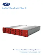
The storage system in an NX4 system is an AX4-5F8.

Summary of tasks for replacing an SPS................................................................................................................2
Handling field replaceable units (FRUs)..............................................................................................................3
Disabling CallHome or ConnectHome and Email notifications......................................................................5
Shutting down power and removing the cables.................................................................................................7
Unlocking and removing the SPS front bezel.....................................................................................................8
Removing the front plate........................................................................................................................................9
Removing a standby power supply....................................................................................................................10
Installing a standby power supply.....................................................................................................................11
Reconnecting Cables and Powering up the SPS................................................................................................12
Installing the front plate.......................................................................................................................................13
Installing and locking the SPS front bezel.........................................................................................................14
Verifying the operation of a new or replacement part.....................................................................................15
Restoring trespassed virtual disks or LUNs using the CLI ............................................................................17
Checking system status........................................................................................................................................18
Enabling CallHome or ConnectHome and Email notifications......................................................................19
Returning the failed part......................................................................................................................................23

EMC

®

AX4-5F8 Architecture for NX4 Series

Replacing a Standby Power Supply 

Summary of Contents for EMC AX4-5F8

Page 1: ...nd removing the SPS front bezel 8 Removing the front plate 9 Removing a standby power supply 10 Installing a standby power supply 11 Reconnecting Cables and Powering up the SPS 12 Installing the front plate 13 Installing and locking the SPS front bezel 14 Verifying the operation of a new or replacement part 15 Restoring trespassed virtual disks or LUNs using the CLI 17 Checking system status 18 En...

Page 2: ...Unlock and remove the bezel 4 Remove the front plate 5 Remove the failed SPS 6 Install the replacement SPS 7 Reinstall the front plate 8 Reconnect cables and power up the replacement SPS 9 Reinstall the front plate 10 Reinstall and lock the bezel 11 Verify the operation of the replacement SPS 12 Restore any trespassed virtual disks or LUNs 13 Check system status 14 Enable CallHome or ConnectHome 2...

Page 3: ...lear the work site of any unnecessary materials or materials that naturally build up electrostatic charge such as foam packaging foam cups cellophane wrappers and similar items Do not remove replacement or upgrade FRUs from their antistatic packaging until you are ready to install them Before you service a storage system gather together the ESD kit and all other materials you will need Once servic...

Page 4: ...ou have done this do not move around the room or touch other furnishings personnel or surfaces until you have installed the FRU When you remove a FRU from the antistatic bag avoid touching any electronic components and circuits on it If you must move around the room or touch other surfaces before installing a FRU first place the FRU back in the antistatic bag When you are ready again to install th...

Page 5: ...e laptop to the primary Control Station Figure 1 on page 5 Serial port Figure 1 Control station serial connection 2 Open the HyperTerminal session using the following settings 19200 Bits per second 8 Data bits None Parity 1 Stop bits None Flow control Auto Detect Emulation ANSI Telnet terminal ID Note If you cannot connect to the HyperTerminal session reboot the Control Station log in and repeat t...

Page 6: ...led nas bin nas_emailuser info Sample output Service Enabled No Recipient Address es miley_bean emc com Carbon Copy Address es Email Server emcmail lss emc com Subject Prefix Celerra Notification NDU through NST Sender Address ConnectHome and Email notifications are now disabled You are now ready to replace the part After completing the part replacement procedure be sure to enable ConnectHome and ...

Page 7: ...on for the SPS power switch SPS A shown 2 Disconnect the SPS cables Note Label the cables for reinstallation later a Unplug the SPS power cord from the site power source and then from the SPS b From the SPS unplug the sense cable and the power cord connecting the SPS to the SP directly above it Shutting down power and removing the cables 7 Shutting down power and removing the cables ...

Page 8: ...ront of the enclosure counterclockwise 2 Press the buttons on the front of the bezel and pull the bezel toward you to release it 3 Save the bezel for reinstallation later Figure 3 Unlocking and removing the front bezel 8 Replacing a Standby Power Supply Unlocking and removing the SPS front bezel ...

Page 9: ... must remove it to replace either SPS 1 Remove the four or six screws on the front plate and remove the front plate Figure 4 on page 9 Figure 4 Removing the front plate 2 Save the front plate and screws for reinstallation later Removing the front plate 9 Removing the front plate ...

Page 10: ...y 1 From the rear remove the four screws that secure the SPS 2 From the front of the cabinet slide the SPS off the tray Figure 5 on page 10 Figure 5 Removing an SPS 10 Replacing a Standby Power Supply Removing a standby power supply ...

Page 11: ...ion Figure 6 on page 11 3 From the rear secure the SPS with four screws that you saved either from removing the back plate if you are adding a second SPS or from removing from a failed SPS if you are replacing an SPS Figure 6 Installing a standby power supply Installing a standby power supply 11 Installing a standby power supply ...

Page 12: ...ower cables to the replacement SPS as shown in and described in the steps that follow the figure a Connect the power cord to the power distribution unit PDU in the cabinet or the site power circuit and to the SPS 3 Power up the SPS by pressing the right side of the SPS power switch Figure 7 on page 12 Figure 7 On position for the SPS switch SPS A shown 12 Replacing a Standby Power Supply Reconnect...

Page 13: ... saved when you removed the plate Figure 8 on page 13 2 If you are adding a second SPS secure that SPS to the front plate with two additional screws that came with the SPS upgrade kit Figure 8 on page 13 Figure 8 Installing the front plate Installing the front plate 13 Installing the front plate ...

Page 14: ...osure Figure 9 on page 14 2 Push the bezel in until you feel it latch into place and pull back on the bezel slightly to ensure it is secured 3 Lock the bezel by inserting and then turning the key clockwise Figure 9 on page 14 Figure 9 Installing and locking the SPS bezel 14 Replacing a Standby Power Supply Installing and locking the SPS front bezel ...

Page 15: ... of an SP in the storage system 2 In the Navisphere Express navigation pane under View click Components 3 Scan the list of components to verify that all components are recognized and working properly If fault lights on storage system are still lit go to the Celerra Tools page on the http Powerlink EMC com website for more information Verifying the operation of a new or replacement part using Navis...

Page 16: ...ghts on storage system are still lit go to the Celerra Tools page on the http Powerlink EMC com website for more information 16 Replacing a Standby Power Supply Verifying the operation of a new or replacement part ...

Page 17: ...n to the primary Control Station as nasadmin and change to the root user su root 2 Determine the storage system serial number storage system ID nas_storage list 3 Restore the virtual disks or LUNs to the correct SP nas_storage failback storage system id For example nas_storage failback APM00070300923 id 1 serial_number APM00070300923 name APM00070300923 acl 0 done This restores the virtual disks o...

Page 18: ... Control Station Checking if NBS clients are started Pass Control Station Checking if NBS configuration exists Pass Control Station Checking if NBS devices are accessible Pass Control Station Checking if NBS service is started Pass Storage System Checking for unsupported storage profile Pass Storage System Checking if Fibre Channel zone checker is set up N A Storage System Checking if Fibre Channe...

Page 19: ...minal session to enable ConnectHome and Email notification 1 From the root directory clear any existing Callhome files and enable ConnectHome nas sbin nas_connecthome service start clear 2 From the ConnectHome configuration determine the connections that are enabled nas sbin nas_connecthome i Sample output Enabling CallHome or ConnectHome and Email notifications 19 Enabling CallHome or ConnectHome...

Page 20: ...t FTP Password FTP Remote Folder incoming FTP Transfer Mode active Modem Priority Disabled Primary Phone Number 918005270941 BT Tymnet no Secondary Phone Number 918006262452 BT Tymnet no 3 Verify that ConnectHome works with the nas sbin nas_connecthome test connec tion_name command for each enabled connection For example nas sbin nas_connecthome t email_1 Sample output ConnectEMC 2 0 27 bl18 Wed A...

Page 21: ...e Recipient Address es field is empty email notifications has not been configured and does not need to be enabled If you want to configure email notifications use the nas bin nas_emailuser command or Celerra Manager to configure it If the Recipient Address es field is populated email notifications was enabled Re enable email notifications a Enable email notifications nas bin nas_emailuser modify e...

Page 22: ...ration and verify that the configured Recipient Address es received the test email nas bin nas_emailuser test Sample output OK 22 Replacing a Standby Power Supply Enabling CallHome or ConnectHome and Email notifications ...

Page 23: ...eturning the failed part Ship the failed part to your service provider as described in the instructions that were included with the replacement part Returning the failed part 23 Returning the failed part ...

Page 24: ...FICALLY DISCLAIMS IMPLIED WARRANTIES OF MERCHANTABILITY OR FITNESS FOR A PARTICULAR PURPOSE Use copying and distribution of any EMC software described in this publication requires an applicable software license For the most up to date regulatory document for your product line go to the Technical Documentation and Advisories section on EMC Powerlink For the most up to date listing of EMC product na...

Reviews: