Promise Technology ultratrak RM8000, User Manual
The Promise Technology ultratrak RM8000 is a cutting-edge storage solution with exceptional performance. Discover its full potential by accessing the comprehensive User Manual. Download it for free from our website and unlock the true power of this remarkable product.
Share
Download


Reviews:
No comments
Related manuals for ultratrak RM8000

M110
Brand: NEC Pages: 16

MultiSync M700
Brand: NEC Pages: 12

M310
Brand: NEC Pages: 78

8-HDD Series
Brand: Dahua Pages: 8

DSN-3400-10 - xStack Storage Area Network Array Hard...
Brand: D-Link Pages: 5
EB8MS
Brand: proavio Pages: 6
Z4SN25NML
Brand: Addonics Technologies Pages: 2
Storwize V5100 MTM 2078-424
Brand: IBM Pages: 144
Sun Storage 2500-M2 Arrays
Brand: Sun Oracle Pages: 20
G-RAID3
Brand: G-Technology Pages: 13
StorEdge S1 Array
Brand: Sun Microsystems Pages: 32
XP7
Brand: HP Pages: 442
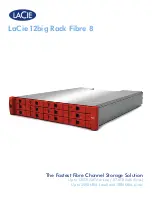
12big Rack Fibre 8
Brand: LaCie Pages: 5
FAS8200 Series
Brand: NetApp Pages: 125
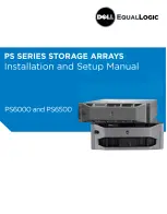
EqualLogic PS Series
Brand: Dell Pages: 62
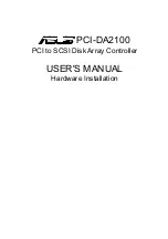
PCI-DA2100
Brand: Asus Pages: 78
D8-30
Brand: NEC Pages: 37

Classixx 1200
Brand: Bosch Pages: 48


