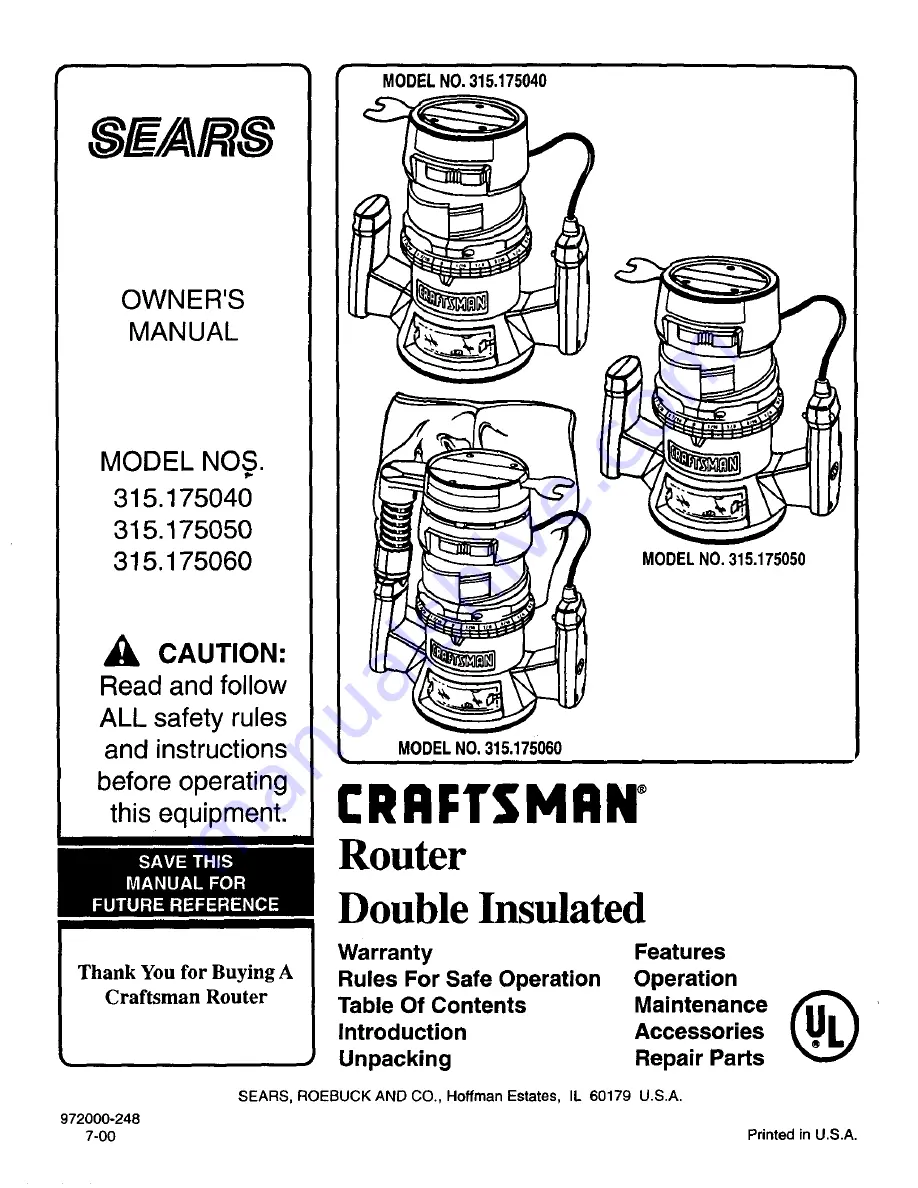
background image

Summary of Contents for 315.17504

Page 1: ...quipment MODEL NO 315 175060 MODEL NO 315 175050 CRRFTSMRNo Router Double Insulated Thank You for Buying A Craftsman Router Warranty Rules For Safe Operation Table Of Contents Introduction Unpacking Features Operation Maintenance _ Accessories Repair Parts SEARS ROEBUCK AND CO Hoffman Estates IL 60179 U S A 972000 248 7 00 Printed in U S A ...

Page 2: ...result in property damage or personal injury to yourself or to others Always follow the safety precautions to reduce the risk of fire electric shock and personal injury NOTE Advises you of information or instructions vital to the operation or maintenance of the equipment DOUBLE INSULATION is a safety concept inelectric power tools which eliminates the need for the usual three wire grounded power c...

Page 3: ... WEAR PROPER APPAREL Do not wear loose clothing or jewelry that can get caught in tool s moving parts and cause personal injury Rubber gloves and non skid footwear are recommended when working outdoors Wear protective hair covering to contain long hair and keep it from being drawn into nearby air vents 19 20 21 ALWAYS WEAR SAFETY GLASSES Everyday eyeglasses have only impact resistant lenses they a...

Page 4: ...s replaced by an authorized service center 32 INSPECT FOR and remove all nails from lumber before routing 34 35 DRUGS ALCOHOL MEDICATION Do not operate tool while under the influence of drugs alcohol or any medication WHEN SERVICING USE ONLY IDENTICAL CRAFTSMAN REPLACEMENT PARTS POLARIZED PLUGS To reduce the risk of electric shock this tool has a polarized plug one blade is wider than the other Th...

Page 5: ...odel Nos 315 175050 and 315 175060 12 Practice Before Actual Use 12 Routing 13 Freehand Routing 13 Proper Feeding 14 Speed Selections Model Noso 315 175050 and 315 175060 Only 14 Rate Of Feed 14 Force Feeding 14 Too Slow Feeding 14 Depth Of Cut 15 Direction Of Feed and Thrust 15 Routing 15 Starting and Ending A Cut Internal Routing 16 Edging With Pilot Bits 16 Edge Routing 16 Routing With Guide Bu...

Page 6: ...e service SPECIFICATIONS DEPTH OF CUT COLLET HORSEPOWER Model No 315 175040 Model No 315 175050 Model No 315 175060 AMPS Model No 315 175040 Model No 315 175050 Model No 315 175060 RATING NO LOAD SPEED Model No 315 175040 Model Nos 315 175050 and 315 175060 POWER CORD Model Nos 315 175040 and 315 175050 Model No 315 175060 0 1 1 2 in 1 4 in DUSTLESS Model No 315 175060 NET WEIGHT Model No 315 1750...

Page 7: ... cap portionofthe motor housing When installing or removing cutters remove the wrench from its storage area Proper storage of wrench when not in use will help reduce the possibility of losing wrench VARIABLE SPEED SWITCH WITH ELECTRONIC SPEED CONTROL MODEL NOS 315 175050 AND 315 175060 ONLY See Figures lb and lc Your router has advanced electronic features designed to assist you in getting the max...

Page 8: ...NING Always wear safety goggles or safety glasses with side shields when operating your router Failure to do so could result indust shavings loose particles or foreign objects being thrown into your eyes causing possible serious injury MODEL NO 315 175040 UPSIDE DOWN VIEW OF ROUTER DEPTH INDICATOR RiNG INDICATOR POINT WRENCH WRENCH STORAGE AREA SPINDLE POWER HANDLE SWITCH HANDLE BUTTON LOCKING KNO...

Page 9: ... TRIGGER_ LOCK ON BUTTON LOCKING KNOB HANDLE DEPTH ADJUSTING RING CHIP SHIELD WRENCH SPINDLE STORAGEAREA ARIABLESPEED CONTROLSELECTOR DEPTH INDICATORRING INDICATOR SUBBASE POINT MODEL NO 315 175050 UPSIDE DOWN VIEW OF ROUTER DEPTH INDICATOR INDICATOR POINT RING WRENCH Fig 1b BLOWER MODEL NO 315 175060 Page 9 ...

Page 10: ...nto position when lock mechanism interlocks WARNING If you are changing a cutter immediately after use be careful not to touch the cutter or toilet with your hands or fingers They will get burned because of the heat buildup from cutting Always use the wrench provided I Remove cutters by turning collet nut counterclockwise enough to allow cutter to slip easily from collet See Figure 3 The collet is...

Page 11: ...ines up with the indicator point on the base NOTE The depth indicator ring is also a zero reset indicator when setting cutter at zero depth of cut then it becomes the depth adjusting ring See Figure 5 Position your router so _at the cutter can extend below the subbase for desired depth setting See Figure 6 Turn the depth adjusting ring to obtain the desired depth of cut The distance the cutter mov...

Page 12: ...nt to use the variable speed control selector turn to the highest possible setting and the feature will not be active PRACTICE BEFORE ACTUAL USE If your router is Model No 315 175050 or 315 175060 we suggest that you practice with the variable speed feature of your router before installing a cutter and making cuts in wood Check the following before connecting your router to power supply Make sure ...

Page 13: ...tures etc There are two basic techniques for freehand routing Routing letters grooves and patterns into wood See Figure 10 Routing out the background leaving the letters or pattern raised above _e surface When freehand routing we suggest the following Draw or layout the pattern on workpiece Choose the appropriate cutter NOTE A core box or V groove bit is often used for routing letters and engravin...

Page 14: ...er chips also require more power which could result in the router motor becoming overloaded Under extreme force feeding conditions the relative RPM of the bit can become so slow and the bites it has to take so large that chips will be partially knocked off rather than fully cut off with resulting splintering and gouging of the workpiece See Figure 11 Your Craftsman Router is an extremely high spee...

Page 15: ...lockwise direction especially when the motor is starting up Because of the extremely high speed of bit rotation during a proper feeding operation there is very little kickback to contend with under normal conditions However should the bit strike a knot hard grain foreign object etc that would affect the normal progress of the cutting action there will be a slight kickback sufficient to spoil the t...

Page 16: ...igure 15 However if the workpiece is too thin or the bit set too low so that there will be no uncut edge to ride the pilot against an extra board to act as a guide must be placed under the workpiece This guide board must have exactly the same contour straight or curved as the workpiece edge If it is positioned so that its edge is flush with the workpiece edge the bit will make a full cut in as far...

Page 17: ...njury SWITCH REPLACEMENT MODEL NO 315 175040 See Figures 16and 17 UNPLUG YOUR ROUTER WARNING Failure to unplug your router could result in accidental starting causing serious injury Remove screws A and handle cover B See Figure 16 Note the location of the molded bend relief C on the power handle cord Also note all wiring in the handle and how each lead is connected to the switch Connections and wi...

Page 18: ...ew switch See Figure 18 Remove leads from switch D by inserting a 1 32 in diameter nail or pin into switch lead receptacle and pulling on lead as sRown in figure 19 Remove nail or pin with a twisting pulling motion Make lead connections to new switch Push each lead as far as possible into proper switch receptacle Pull on leads to check lead connections with lead receptacles Locate switch in handle...

Page 19: ...originally ground PROPER CARE OF COLLET From time to time it also becomes necessary to clean your collet and collet nut To do so simply remove collet nut from collet and clean the dust and chips that have collected Then return eollet nut to its original position LUBRICATION All of the bearings in this tool are lubricated with a sufficient amount of high grade lubricant for the life of the unit und...

Page 20: ...g compounds or plaster it has been found that they are subject to accelerated wear and possible premature failure as the fiberglass chips and grindings are highly abrasive to bearings brushes commutators etc Consequently it is not recommended that this tool be used for extende_ work on any fiberglass material wallboard spackling compounds or plaster During any use on these materials it is extremel...

Page 21: ...B INATION STRAIGHT BEVEL CUTTER HINGE MORTISING BIT DOVETAILRABBET OGEE CUTTER BIT rOMANC BITS I CARBIDETIPPEDBITS I COVE BIT 45 CHAMFER BIT 25895FORCARBIDETIPPEDEDGEFORMINGBITS 2589FORHIGHSPEEDSTEELEDGEFORMINGBITS BEAD IARBOR QUARTER 2589 ROUND I BITS WITH2 BALL 3EARINGS 1 2IN G _iN 2G89G I i _i_ v_i_ _ i_i_ _i_i_i_i_ii i_i i_iiiiiii_i _ii _i_Ti_ii_i_i_i_ii i_i _ i _i_ _ _ i i _ iii_ i _ _ _ _ _ ...

Page 22: ...hown represents an important part of the Double Insulated System To avoid the possibility of alteration or damage to the System service should be performed by your nearest Sears Repair Center Contact your nearest Sears Retail Store for Service Center information Page 22 ...

Page 23: ...96 000 19 610951 001 20 998895 001 21 623173 006 22 999603 001 23 931744 059 24 970855 001 25 989935 006 972000 248 PARTS LIST Description Quan Data Plate _ 1 Label 1 Collet Nut 1 4 in 1 Depth Adjusting Ring Assembly Includes Key No 24 1 Depth Indicator Ring 1 Square Head Bolt 1 4 20 x 1 1 4 in 1 Roll Pin 1 Screw 10 32 x 3 4 in Pan Hd 4 Screw 8 10 x 5 8 in Pan Hd 8 Handle Assembly 1 Base 1 Chip Sh...

Page 24: ... shown represents an important part of the Double Insulated System To avoid the possibility of alteration or damage to the System service should be performed by your nearest Sears Repair Center Contact your nearest Sears Retail Store for Service Center information Page 24 ...

Page 25: ... 22 623173 006 23 998895 002 24 610951 001 25 999603 001 26 931744 059 27 970855 001 28 989935 006 972000 248 PARTS LIST Description Quan Data Plate 1 Label 1 Collet Nut 1 4 in 1 Depth Adjusting Ring Assembly Includes Key No 27 1 Depth Indicator Ring 1 Square Head Bolt 1 4 20 x 1 1 4 in 1 Roll Pin 1 Screw 10 32 x 3 4 in Pan Hd 4 Screw 8 10 x 5 8 in Pan Hd 8 Handle Assembly 1 Base 1 Chip Shield 1 S...

Page 26: ...e assembly shown represents an important part of the Double Insulated System To avoid the possibility of alteration or damage to the system service should be performed by your nearest Sears Repair Center Contact your nearest Sears Retail Store for Service Center information Page 26 ...

Page 27: ...Depth Adjusting Ring Assembly Includes Key No 35 1 Vacuum Hose 1 Depth Indicator Ring 1 Square Head Bolt 1 4 20 x 1 1 4 in 1 Roll Pin 1 Screw 10 32 x 314 in Pan Hd 4 Screw 8 10 x 5 8 in Pan Hd 8 Handle Assembly 1 Key PaM No Number Description 19 973735 204 20 606688 002 21 998586 001 22 612191 004 23 989684 001 24 975041 001 25 990822 002 26 610930 002 27 970793 007 28 970793 008 29 970698 000 30 ...

Page 28: ...d owner s manuals that you need to do it yourself call Sears PartsDirect sM 1 800 366 PART 6 a m 11 p m CST 1 800 366 7278 7 days a week www sears condpartsdirect To purchase or inquire about a Sears Service Agreement 1 800 827 6655 7 a m 5 p m CST Mon Sat Para pedir servicio de reparacibn a domicilio y para ordenar piezas con entrega a domicilio 1 888 SU HOGAR sM 1 888 784 6427 Au Canada pour ser...

Reviews: